1995 ACURA TL check oil
[x] Cancel search: check oilPage 479 of 1771
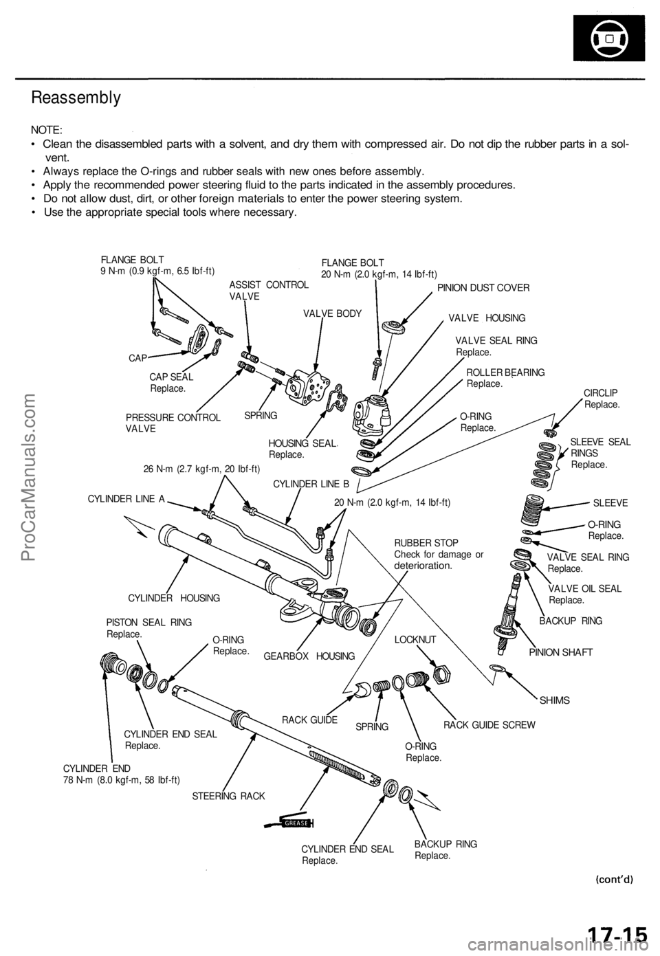
Reassembly
NOTE:
• Clean the disassembled parts with a solvent, and dry them with compressed air. Do not dip the rubber parts in a sol-
vent.
• Always replace the O-rings and rubber seals with new ones before assembly.
• Apply the recommended power steering fluid to the parts indicated in the assembly procedures.
• Do not allow dust, dirt, or other foreign materials to enter the power steering system.
• Use the appropriate special tools where necessary.
FLANGE BOLT
9 N-m (0.9 kgf-m, 6.5 Ibf-ft)
FLANGE BOLT
20 N-m (2.0 kgf-m, 14 Ibf-ft)
CAP
PINION DUST COVER
VALVE HOUSING
26 N-m (2.7 kgf-m, 20 Ibf-ft)
CYLINDER LINE A
VALVE OIL SEAL
Replace.
SHIMS
CYLINDER END
78 N-m (8.0 kgf-m, 58 Ibf-ft)
CYLINDER END SEAL
Replace.
BACKUP RING
Replace.
CAP SEAL
Replace.
PRESSURE CONTROL
VALVE
SPRING
HOUSING SEAL
Replace.
CYLINDER LINE B
VALVE BODY
ASSIST CONTROL
VALVE
VALVE SEAL RING
Replace.
ROLLER BEARING
Replace.
O-RING
Replace.
SLEEVE SEAL
RINGS
Replace.
CIRCLIP
Replace.
SLEEVE
20 N-m (2.0 kgf-m, 14 Ibf-ft)
BACKUP RING
PINION SHAFT
LOCKNUT
RACK GUIDE SCREW
O-RING
Replace.
SPRING
RACK GUIDE
STEERING RACK
CYLINDER END SEAL
Replace.
PISTON SEAL RING
Replace.
CYLINDER HOUSING
GEARBOX HOUSING
O-RING
Replace.
RUBBER STOP
Check for damage or
deterioration.
VALVE SEAL RING
Replace.
O-RING
Replace.ProCarManuals.com
Page 562 of 1771
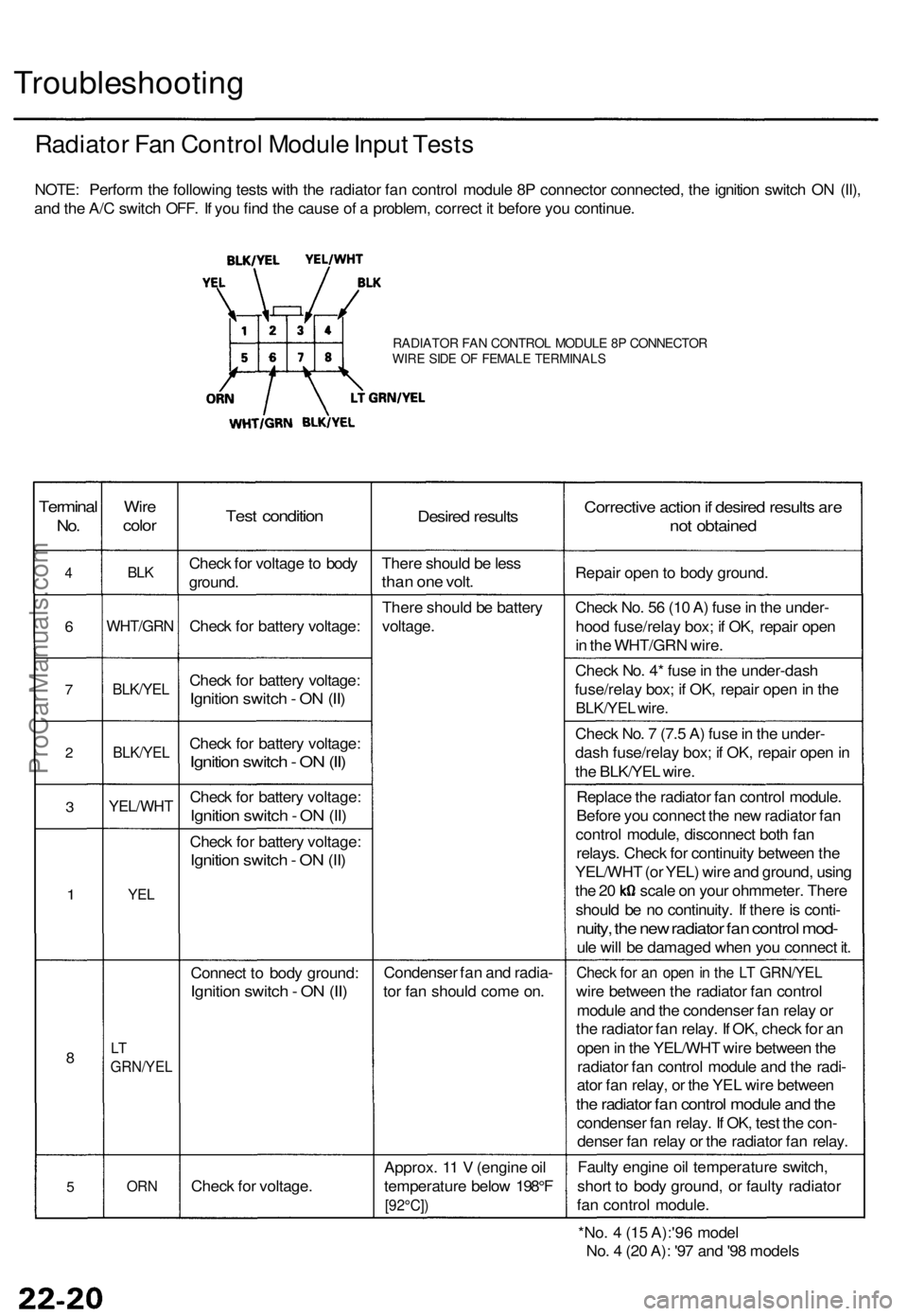
Troubleshooting
Radiator Fan Control Module Input Tests
NOTE: Perform the following tests with the radiator fan control module 8P connector connected, the ignition switch ON (II),
and the A/C switch OFF. If you find the cause of a problem, correct it before you continue.
RADIATOR FAN CONTROL MODULE 8P CONNECTOR
WIRE SIDE OF FEMALE TERMINALS
Terminal
No.
4
6
7
2
3
1
8
5
Wire
color
BLK
WHT/GRN
BLK/YEL
BLK/YEL
YEL/WHT
YEL
LT
GRN/YEL
ORN
Test condition
Check for voltage to body
ground.
Check for battery voltage:
Check for battery voltage:
Ignition switch - ON (II)
Check for battery voltage:
Ignition switch - ON (II)
Check for battery voltage:
Ignition switch - ON (II)
Check for battery voltage:
Ignition switch - ON (II)
Connect to body ground:
Ignition switch - ON (II)
Check for voltage.
Desired results
There should be less
than one volt.
There should be battery
voltage.
Condenser fan and radia-
tor fan should come on.
Approx. 11 V (engine oil
temperature below 198°F
[92°C])
Corrective action if desired results are
not obtained
Repair open to body ground.
Check No. 56 (10 A) fuse in the under-
hood fuse/relay box; if OK, repair open
in the WHT/GRN wire.
Check No. 4* fuse in the under-dash
fuse/relay box; if OK, repair open in the
BLK/YEL wire.
Check No. 7 (7.5 A) fuse in the under-
dash fuse/relay box; if OK, repair open in
the BLK/YEL wire.
Replace the radiator fan control module.
Before you connect the new radiator fan
control module, disconnect both fan
relays. Check for continuity between the
YEL/WHT (or YEL) wire and ground, using
the 20 scale on your ohmmeter. There
should be no continuity. If there is conti-
nuity, the new radiator fan control mod-
ule will be damaged when you connect it.
Check for an open in the LT GRN/YEL
wire between the radiator fan control
module and the condenser fan relay or
the radiator fan relay. If OK, check for an
open in the YEL/WHT wire between the
radiator fan control module and the radi-
ator fan relay, or the YEL wire between
the radiator fan control module and the
condenser fan relay. If OK, test the con-
denser fan relay or the radiator fan relay.
Faulty engine oil temperature switch,
short to body ground, or faulty radiator
fan control module.
*No. 4 (15 A):'96 model
No. 4 (20 A): '97 and '98 modelsProCarManuals.com
Page 565 of 1771
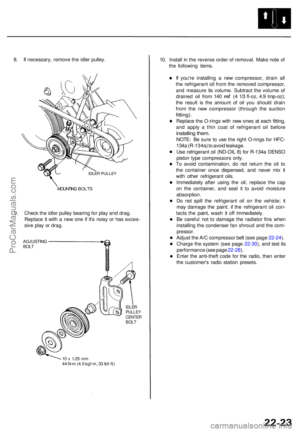
8. I f necessary , remov e th e idle r pulley .
IDLER PULLE Y
9.
MOUNTIN G BOLT S
Check th e idle r pulle y bearin g fo r pla y an d drag .
Replac e it wit h a ne w on e i f it' s nois y o r ha s exces -
siv e pla y o r drag .
ADJUSTIN GBOLT
IDLE RPULLE YCENTE RBOLT
10 x 1.2 5 mm44 N- m (4. 5 kgf-m , 3 3 Ibf-ft )
10. Instal l i n th e revers e orde r o f removal . Mak e not e o f
th e followin g items .
I f you'r e installin g a ne w compressor , drai n al l
th e refrigeran t oi l fro m th e remove d compressor ,
an d measur e it s volume . Subtrac t th e volum e o f
draine d oi l fro m 14 0 ( 4 1/ 3 fl-oz , 4. 9 Imp-oz) ;
th e resul t i s th e amoun t o f oi l yo u shoul d drai n
fro m th e ne w compresso r (throug h th e suctio n
fitting).
Replac e th e O-rings with ne w one s a t eac h fitting ,
an d appl y a thi n coa t of refrigeran t oi l befor e
installin g them .
NOTE : B e sur e t o us e th e righ t O-ring s fo r HFC -
134 a (R-134a ) t o avoi d leakage .
Us e refrigeran t oi l (ND-OI L 8 ) fo r R-134 a DENS O
pisto n typ e compressor s only .
T o avoi d contamination , d o no t retur n th e oi l t o
th e containe r onc e dispensed , an d neve r mi x i t
wit h othe r refrigeran t oils .
Immediatel y afte r usin g th e oil , replac e th e ca p
o n th e container , an d sea l i t t o avoi d moistur e
absorption .
D o no t spil l th e refrigeran t oi l o n th e vehicle ; i t
ma y damag e th e paint ; i f th e refrigeran t oi l con -
tact s th e paint , was h i t of f immediately .
B e carefu l no t t o damag e th e radiato r fin s whe n
installin g th e condense r fa n shrou d an d th e com -
pressor .
Adjust th e A/ C compresso r bel t (se e pag e 22-24 ).
Charg e th e syste m (se e pag e 22-30 ), an d tes t it s
performanc e (se e pag e 22-28 ).
Ente r th e anti-thef t cod e fo r th e radio , the n ente r
th e customer' s radi o statio n presets .
ProCarManuals.com
Page 586 of 1771
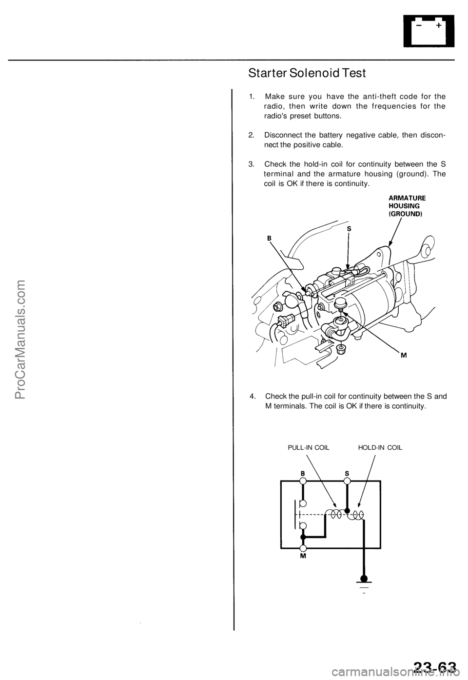
Starter Solenoid Test
1. Make sure you have the anti-theft code for the
radio, then write down the frequencies for the
radio's preset buttons.
2. Disconnect the battery negative cable, then discon-
nect the positive cable.
3. Check the hold-in coil for continuity between the S
terminal and the armature housing (ground). The
coil is OK if there is continuity.
4. Check the pull-in coil for continuity between the S and
M terminals. The coil is OK if there is continuity.
PULL-IN COIL HOLD-IN COILProCarManuals.com
Page 758 of 1771
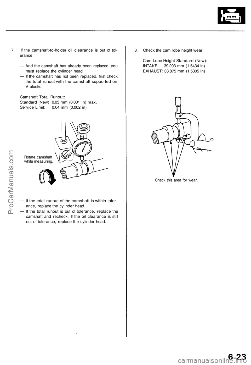
7. If the camshaft-to-holder oil clearance is out of tol-
erance:
— And the camshaft has already been replaced, you
must replace the cylinder head.
— If the camshaft has not been replaced, first check
the total runout with the camshaft supported on
V-blocks.
Camshaft Total Runout:
Standard (New): 0.03 mm (0.001 in) max.
Service Limit: 0.04 mm (0.002 in)
Rotate camshaft
while measuring.
If the total runout of the camshaft is within toler-
ance, replace the cylinder head.
If the total runout is out of tolerance, replace the
camshaft and recheck. If the oil clearance is still
out of tolerance, replace the cylinder head.
8. Check the cam lobe height wear.
Cam Lobe Height Standard (New):
INTAKE: 39.203 mm (1.5434 in)
EXHAUST: 38.875 mm (1.5305 in)
Check this area for wear.ProCarManuals.com
Page 775 of 1771
Cylinder Head
Installation (cont'd)
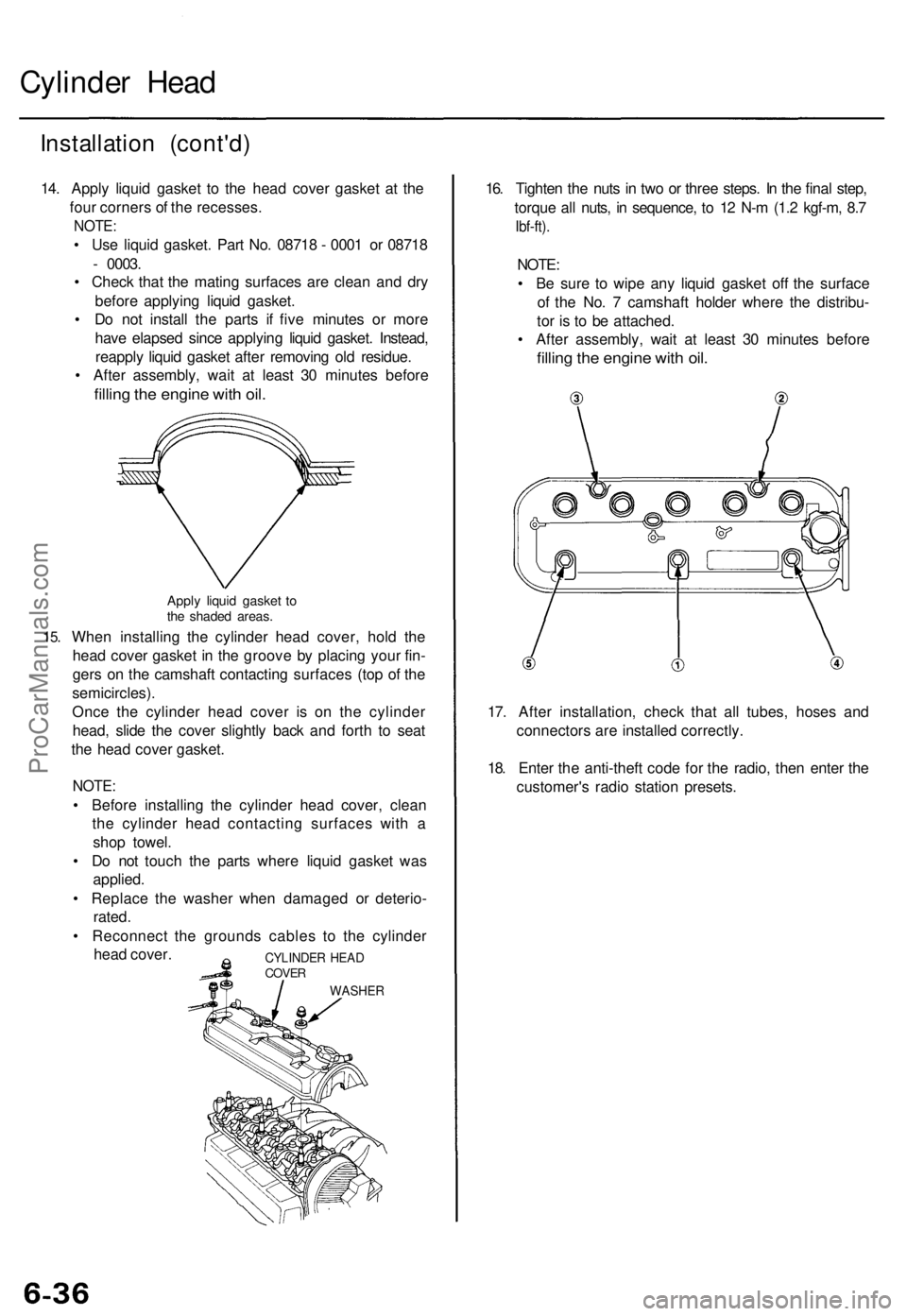
14. Apply liquid gasket to the head cover gasket at the
four corners of the recesses.
NOTE:
• Use liquid gasket. Part No. 08718 - 0001 or 08718
- 0003.
• Check that the mating surfaces are clean and dry
before applying liquid gasket.
• Do not install the parts if five minutes or more
have elapsed since applying liquid gasket. Instead,
reapply liquid gasket after removing old residue.
• After assembly, wait at least 30 minutes before
filling the engine with oil.
15.
Apply liquid gasket to
the shaded areas.
When installing the cylinder head cover, hold the
head cover gasket in the groove by placing your fin-
gers on the camshaft contacting surfaces (top of the
semicircles).
Once the cylinder head cover is on the cylinder
head, slide the cover slightly back and forth to seat
the head cover gasket.
NOTE:
• Before installing the cylinder head cover, clean
the cylinder head contacting surfaces with a
shop towel.
• Do not touch the parts where liquid gasket was
applied.
• Replace the washer when damaged or deterio-
rated.
• Reconnect the grounds cables to the cylinder
head cover.
16. Tighten the nuts in two or three steps. In the final step,
torque all nuts, in sequence, to 12 N-m (1.2 kgf-m, 8.7
Ibf-ft).
NOTE:
• Be sure to wipe any liquid gasket off the surface
of the No. 7 camshaft holder where the distribu-
tor is to be attached.
• After assembly, wait at least 30 minutes before
filling the engine with oil.
17. After installation, check that all tubes, hoses and
connectors are installed correctly.
18. Enter the anti-theft code for the radio, then enter the
customer's radio station presets.
CYLINDER HEAD
COVER
WASHERProCarManuals.com
Page 781 of 1771
Main Bearings
Clearance
1. To check main bearing-to-journal oil clearance,
remove the main caps and bearing halves.
2. Clean each main journal and bearing half with a
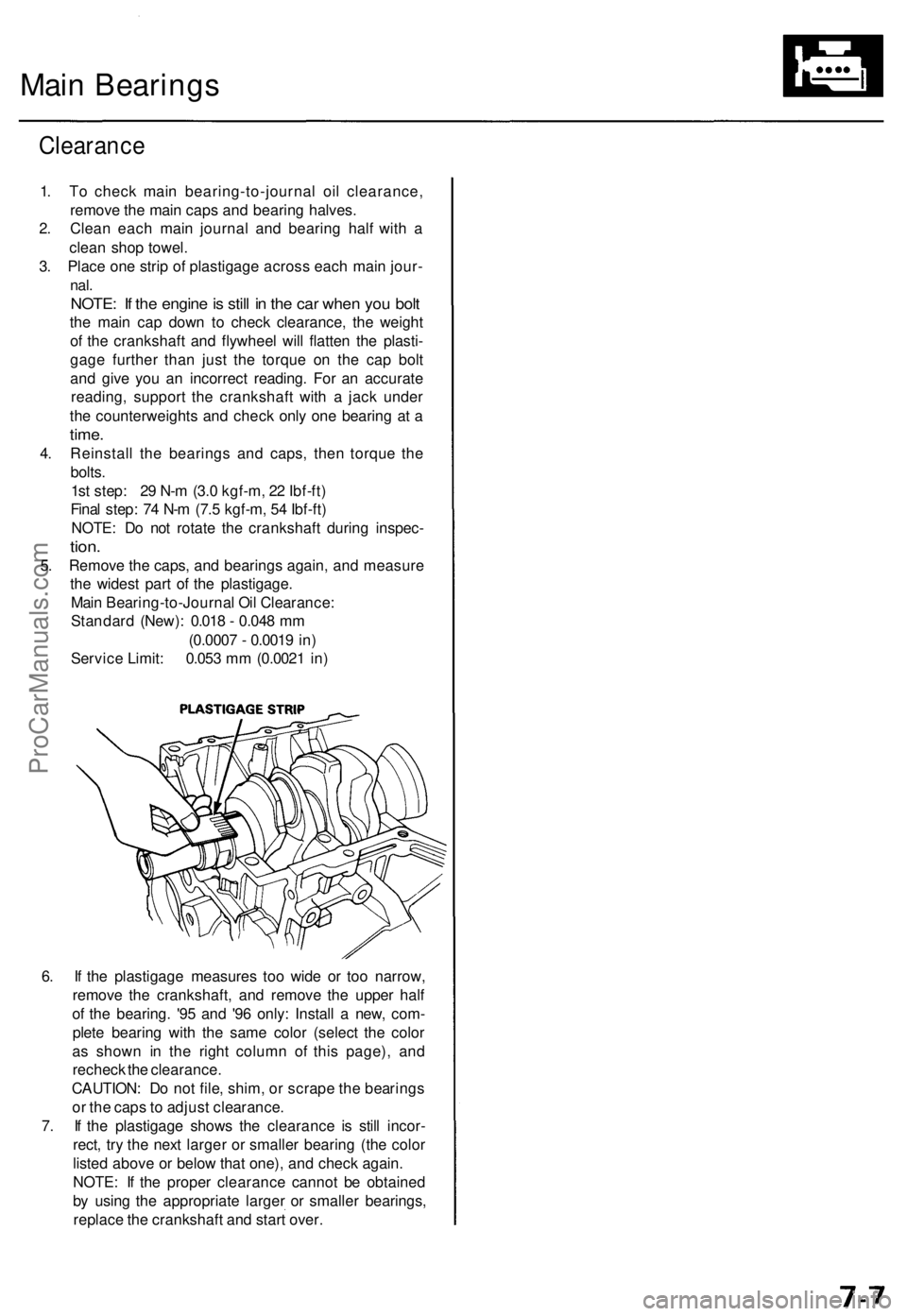
clean shop towel.
3. Place one strip of plastigage across each main jour-
nal.
NOTE: If the engine is still in the car when you bolt
the main cap down to check clearance, the weight
of the crankshaft and flywheel will flatten the plasti-
gage further than just the torque on the cap bolt
and give you an incorrect reading. For an accurate
reading, support the crankshaft with a jack under
the counterweights and check only one bearing at a
time.
4. Reinstall the bearings and caps, then torque the
bolts.
1st step: 29 N-m (3.0 kgf-m, 22 Ibf-ft)
Final step: 74 N-m (7.5 kgf-m, 54 Ibf-ft)
NOTE: Do not rotate the crankshaft during inspec-
tion.
5. Remove the caps, and bearings again, and measure
the widest part of the plastigage.
Main Bearing-to-Journal Oil Clearance:
Standard (New): 0.018 - 0.048 mm
(0.0007 - 0.0019 in)
Service Limit: 0.053 mm (0.0021 in)
6. If the plastigage measures too wide or too narrow,
remove the crankshaft, and remove the upper half
of the bearing. '95 and '96 only: Install a new, com-
plete bearing with the same color (select the color
as shown in the right column of this page), and
recheck the clearance.
CAUTION: Do not file, shim, or scrape the bearings
or the caps to adjust clearance.
7. If the plastigage shows the clearance is still incor-
rect, try the next larger or smaller bearing (the color
listed above or below that one), and check again.
NOTE: If the proper clearance cannot be obtained
by using the appropriate larger or smaller bearings,
replace the crankshaft and start over.ProCarManuals.com
Page 784 of 1771
Connecting Rod Bearings
Clearance
1. Remove the connecting rod cap and bearing half.
2. Clean the crankshaft rod journal and bearing half
with a clean shop towel.
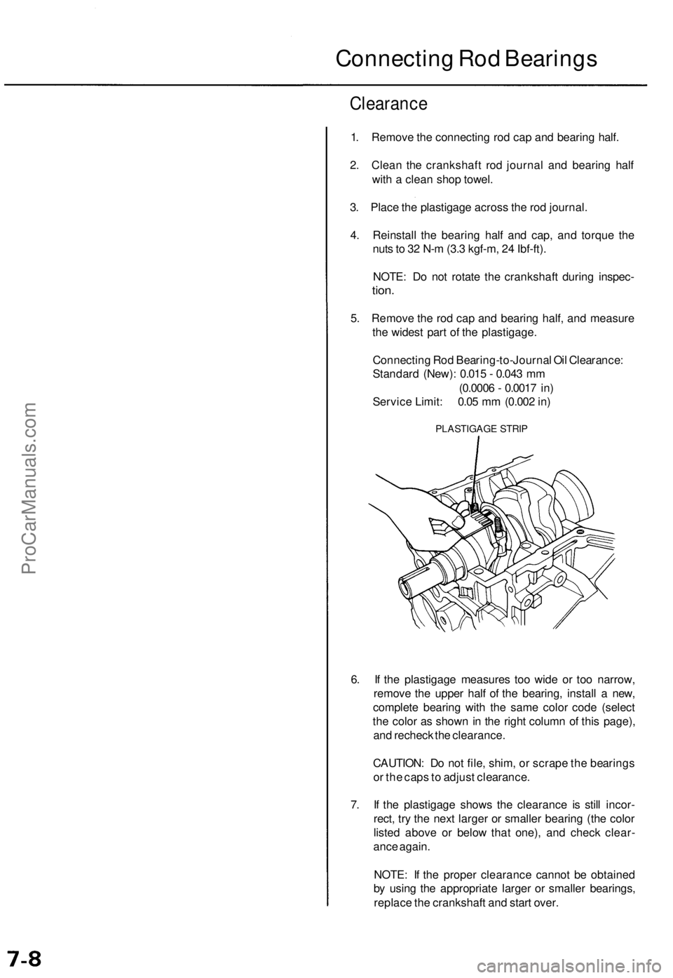
3. Place the plastigage across the rod journal.
4. Reinstall the bearing half and cap, and torque the
nuts to 32 N-m (3.3 kgf-m, 24 Ibf-ft).
NOTE: Do not rotate the crankshaft during inspec-
tion.
5. Remove the rod cap and bearing half, and measure
the widest part of the plastigage.
Connecting Rod Bearing-to-Journal Oil Clearance:
Standard (New): 0.015 - 0.043 mm
(0.0006 - 0.0017 in)
Service Limit: 0.05 mm (0.002 in)
PLASTIGAGE STRIP
6. If the plastigage measures too wide or too narrow,
remove the upper half of the bearing, install a new,
complete bearing with the same color code (select
the color as shown in the right column of this page),
and recheck the clearance.
CAUTION: Do not file, shim, or scrape the bearings
or the caps to adjust clearance.
7. If the plastigage shows the clearance is still incor-
rect, try the next larger or smaller bearing (the color
listed above or below that one), and check clear-
ance again.
NOTE: If the proper clearance cannot be obtained
by using the appropriate larger or smaller bearings,
replace the crankshaft and start over.ProCarManuals.com