1994 JEEP CHEROKEE relay
[x] Cancel search: relayPage 494 of 1784

WIRING DIAGRAMS
CONTENTS
page page
FUSE CHARTS AND RELAY BANKS......... 8
GENERAL INFORMATION.................. 1
SPLICE LOCATIONS..................... 53
WIRING AND COMPONENT IDENTIFICATION . 13WIRING DIAGRAMS XJ.................. 149
WIRING DIAGRAMS XJ RHD............. 271
WIRING DIAGRAMS YJ.................. 73
GENERAL INFORMATION
INDEX
page page
Circuit Identification........................ 2
Component Identification.................... 2
Connector and Terminal Assembly Replacement . . 5
Connector Replacement.................... 4
Connectors.............................. 3
Fusible Link Replacement................... 4
Fusible Links............................. 3
Locating A System........................ 2Secondary Ignition Wiring................... 1
Splice Locations.......................... 2
Symbols, Fuses and Abbreviations............ 6
Terminal Replacement...................... 5
Troubleshooting Wiring Problems.............. 3
Wire Code Identification.................... 2
Wiring Diagram Sheets and Indexes........... 1
Wiring Repair............................ 4
The wiring diagrams contain the latest information
at the time of publication.
Throughout this group references may be made to
a particular vehicle by letter or number designation.
A chart showing the breakdown of these designations
is included in the Introduction Section at the front of
this service manual.
SECONDARY IGNITION WIRING
Secondary ignition wiring is shown in Figures 1
and 2. For additional information on ignition systems
or distributor operation refer to Group 8D Ignition
Systems.
WIRING DIAGRAM SHEETS AND INDEXES
The diagrams are organized to show the basic ve-
hicle and all of its options. Add-on or non-factory op-
tions are not covered. The diagram pages are
identified by a sheet number which is located at the
lower right or left hand corner of each sheet.Page
numbers at the top of each page do not apply to
diagram sheets.
Diagram sheets show all information relating to
the system. This includes feeds, grounds, switch in-
ternal circuity, connectors, splices, and pin identifica-
tion for controllers and modules. All components,switches, and relays are shown in the at rest position
with the key removed from the ignition and the doors
closed.
In certain instances a wire may be referenced to
another sheet. When this happens, the wire will be
identified as to where it is going.
The index used for the diagrams is located at the
beginning of the section. The main system and all re-
lated components are covered.
Fig. 1 Secondary Ignition Wiring 2.5L
JWIRING DIAGRAMS 8W - 1
Page 499 of 1784

(10) Spread the strands of the wire apart on each
of the exposed wires (Fig. 7 example 1).
(11) Push the two ends of wire together until the
strands of wire are close to the insulation (Fig. 7 ex-
ample 2).
(12) Twist the wires together (Fig. 7 example 3).
(13) Solder the connection together using rosin
core type solder only.Do not use acid core solder.
(14) Center the heat shrink tubing over the joint
and heat using a heat gun. Heat the joint until the
tubing is tightly sealed and sealant comes out of both
ends of the tubing.
(15) Insert the repaired wire into the connector.
(16) Install the connector locking wedge and recon-
nect the connector to its mating half.
(17) Re-tape the wire harness starting 1-1/2 inches
behind the connector and 2 inches past the repair.(18) Connect battery and test affected systems.
SYMBOLS, FUSES AND ABBREVIATIONS
Various symbols are used throughout the wiring di-
agrams. These symbols can be identified by referring
to the symbol identification chart (Fig. 11).
Certain abbreviations are also used in the dia-
grams. These have been developed in such a way
that there meaning should be clear. For fuse block,
relay bank, and power distribution center informa-
tion refer to the fuse charts and relay bank index.
CAUTION: When replacing a blown fuse it is impor-
tant to replace it with a fuse having the correct am-
perage rating. The use of a fuse with a rating other
than indicated may result in an electrical overload.
If a proper rated fuse continues to blow, it indicates
a problem that should be corrected.
8W - 6 WIRING DIAGRAMSJ
Page 501 of 1784
FUSE CHARTS AND RELAY BANKS
INDEX
Fig. Fig.
Fuse Panel XJ........................... 2
Fuse Panel YJ........................... 1Power Distribution Center YJ................. 3
Power Distribution Center XJ................. 4
8W - 8 WIRING DIAGRAMSJ
Page 566 of 1784
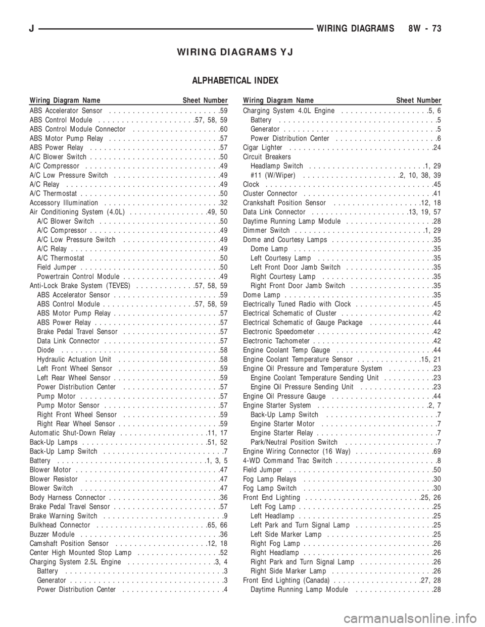
WIRING DIAGRAMS YJ
ALPHABETICAL INDEX
Wiring Diagram Name Sheet Number
ABS Accelerator Sensor........................59
ABS Control Module.....................57, 58, 59
ABS Control Module Connector...................60
ABS Motor Pump Relay........................57
ABS Power Relay............................57
A/C Blower Switch............................50
A/C Compressor.............................49
A/C Low Pressure Switch.......................49
A/C Relay.................................49
A/C Thermostat..............................50
Accessory Illumination.........................32
Air Conditioning System (4.0L).................49, 50
A/C Blower Switch..........................50
A/C Compressor............................49
A/C Low Pressure Switch.....................49
A/C Relay................................49
A/C Thermostat............................50
Field Jumper..............................50
Powertrain Control Module.....................49
Anti-Lock Brake System (TEVES).............57, 58, 59
ABS Accelerator Sensor.......................59
ABS Control Module....................57, 58, 59
ABS Motor Pump Relay.......................57
ABS Power Relay...........................57
Brake Pedal Travel Sensor.....................57
Data Link Connector.........................57
Diode..................................58
Hydraulic Actuation Unit......................58
Left Front Wheel Sensor......................59
Left Rear Wheel Sensor.......................59
Power Distribution Center.....................57
Pump Motor..............................57
Pump Motor Sensor.........................57
Right Front Wheel Sensor.....................59
Right Rear Wheel Sensor......................59
Automatic Shut-Down Relay...................11, 17
Back-Up Lamps...........................51, 52
Back-Up Lamp Switch..........................7
Battery................................1,3,5
Blower Motor...............................47
Blower Resistor.............................47
Blower Switch..............................47
Body Harness Connector........................36
Brake Pedal Travel Sensor.......................57
Brake Warning Switch..........................9
Bulkhead Connector........................65, 66
Buzzer Module..............................36
Camshaft Position Sensor....................12, 18
Center High Mounted Stop Lamp..................52
Charging System 2.5L Engine...................3,4
Battery..................................3
Generator.................................3
Power Distribution Center......................4Wiring Diagram Name Sheet Number
Charging System 4.0L Engine...................5,6
Battery..................................5
Generator.................................5
Power Distribution Center......................6
Cigar Lighter...............................24
Circuit Breakers
Headlamp Switch.........................1,29
#11 (W/Wiper).....................2,10,38,39
Clock....................................45
Cluster Connector............................41
Crankshaft Position Sensor...................12, 18
Data Link Connector.....................13, 19, 57
Daytime Running Lamp Module...................28
Dimmer Switch............................1,29
Dome and Courtesy Lamps......................35
Dome Lamp..............................35
Left Courtesy Lamp.........................35
Left Front Door Jamb Switch...................35
Right Courtesy Lamp........................35
Right Front Door Jamb Switch..................35
Dome Lamp................................35
Electrically Tuned Radio with Clock.................45
Electrical Schematic of Cluster....................42
Electrical Schematic of Gauge Package..............44
Electronic Speedometer.........................42
Electronic Tachometer..........................42
Engine Coolant Temp Gauge.....................44
Engine Coolant Temperature Sensor..............15, 21
Engine Oil Pressure and Temperature System..........23
Engine Coolant Temperature Sending Unit...........23
Engine Oil Pressure Sending Unit................23
Engine Oil Pressure Gauge......................44
Engine Starter System........................2,7
Back-Up Lamp Switch........................7
Engine Starter Motor.........................7
Engine Starter Relay..........................7
Park/Neutral Position Switch....................7
Engine Wiring Connector (16 Way).................69
4-WD Command Trac Switch......................8
Field Jumper...............................50
Fog Lamp Relays............................30
Fog Lamp Switch............................30
Front End Lighting.........................25, 26
Left Fog Lamp.............................25
Left Headlamp.............................25
Left Park and Turn Signal Lamp.................25
Left Side Marker Lamp.......................25
Right Fog Lamp............................26
Right Headlamp............................26
Right Park and Turn Signal Lamp................26
Right Side Marker Lamp......................26
Front End Lighting (Canada)...................27, 28
Daytime Running Lamp Module.................28
JWIRING DIAGRAMS 8W - 73
Page 567 of 1784
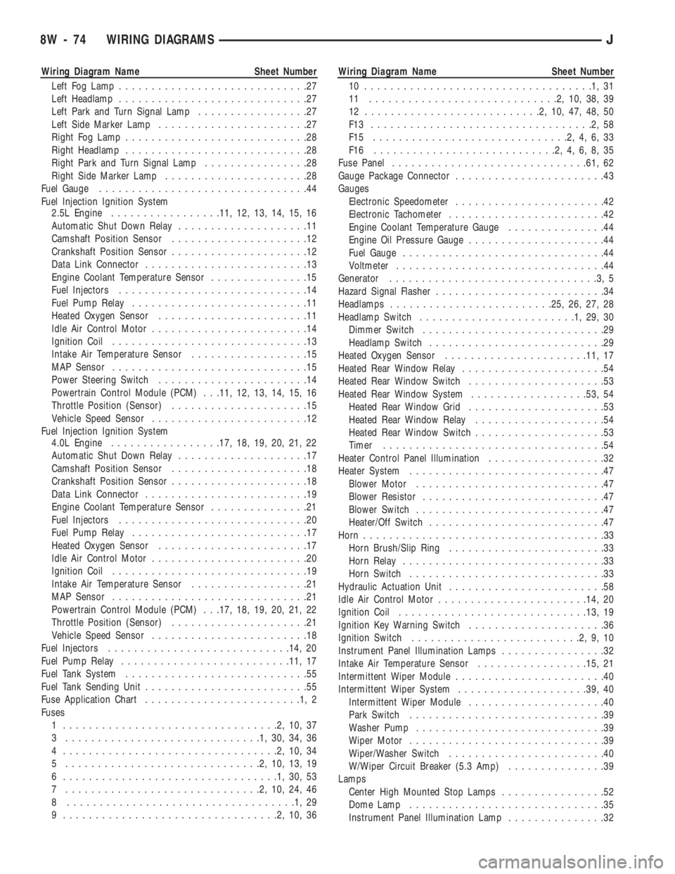
Wiring Diagram Name Sheet Number
Left Fog Lamp.............................27
Left Headlamp.............................27
Left Park and Turn Signal Lamp.................27
Left Side Marker Lamp.......................27
Right Fog Lamp............................28
Right Headlamp............................28
Right Park and Turn Signal Lamp................28
Right Side Marker Lamp......................28
Fuel Gauge................................44
Fuel Injection Ignition System
2.5L Engine.................11, 12, 13, 14, 15, 16
Automatic Shut Down Relay....................11
Camshaft Position Sensor.....................12
Crankshaft Position Sensor.....................12
Data Link Connector.........................13
Engine Coolant Temperature Sensor...............15
Fuel Injectors.............................14
Fuel Pump Relay...........................11
Heated Oxygen Sensor.......................11
Idle Air Control Motor........................14
Ignition Coil..............................13
Intake Air Temperature Sensor..................15
MAP Sensor..............................15
Power Steering Switch.......................14
Powertrain Control Module (PCM) . . .11, 12, 13, 14, 15, 16
Throttle Position (Sensor).....................15
Vehicle Speed Sensor........................12
Fuel Injection Ignition System
4.0L Engine.................17, 18, 19, 20, 21, 22
Automatic Shut Down Relay....................17
Camshaft Position Sensor.....................18
Crankshaft Position Sensor.....................18
Data Link Connector.........................19
Engine Coolant Temperature Sensor...............21
Fuel Injectors.............................20
Fuel Pump Relay...........................17
Heated Oxygen Sensor.......................17
Idle Air Control Motor........................20
Ignition Coil..............................19
Intake Air Temperature Sensor..................21
MAP Sensor..............................21
Powertrain Control Module (PCM) . . .17, 18, 19, 20, 21, 22
Throttle Position (Sensor).....................21
Vehicle Speed Sensor........................18
Fuel Injectors............................14, 20
Fuel Pump Relay..........................11, 17
Fuel Tank System............................55
Fuel Tank Sending Unit.........................55
Fuse Application Chart........................1,2
Fuses
1 .................................2,10,37
3 ..............................1,30,34,36
4 .................................2,10,34
5 ..............................2,10,13,19
6 .................................1,30,53
7 ..............................2,10,24,46
8 ...................................1,29
9 .................................2,10,36Wiring Diagram Name Sheet Number
10 ...................................1,31
11 .............................2,10,38,39
12 ...........................2,10,47,48,50
F13 ..................................2,58
F15 ..............................2,4,6,33
F16 ............................2,4,6,8,35
Fuse Panel..............................61, 62
Gauge Package Connector.......................43
Gauges
Electronic Speedometer.......................42
Electronic Tachometer........................42
Engine Coolant Temperature Gauge...............44
Engine Oil Pressure Gauge.....................44
Fuel Gauge...............................44
Voltmeter................................44
Generator................................3,5
Hazard Signal Flasher..........................34
Headlamps.........................25, 26, 27, 28
Headlamp Switch........................1,29,30
Dimmer Switch............................29
Headlamp Switch...........................29
Heated Oxygen Sensor......................11, 17
Heated Rear Window Relay......................54
Heated Rear Window Switch.....................53
Heated Rear Window System..................53, 54
Heated Rear Window Grid.....................53
Heated Rear Window Relay....................54
Heated Rear Window Switch....................53
Timer..................................54
Heater Control Panel Illumination..................32
Heater System..............................47
Blower Motor.............................47
Blower Resistor............................47
Blower Switch.............................47
Heater/Off Switch...........................47
Horn.....................................33
Horn Brush/Slip Ring........................33
Horn Relay...............................33
Horn Switch..............................33
Hydraulic Actuation Unit........................58
Idle Air Control Motor.......................14, 20
Ignition Coil.............................13, 19
Ignition Key Warning Switch.....................36
Ignition Switch..........................2,9,10
Instrument Panel Illumination Lamps................32
Intake Air Temperature Sensor.................15, 21
Intermittent Wiper Module.......................40
Intermittent Wiper System....................39, 40
Intermittent Wiper Module.....................40
Park Switch..............................39
Washer Pump.............................39
Wiper Motor..............................39
Wiper/Washer Switch........................40
W/Wiper Circuit Breaker (5.3 Amp)...............39
Lamps
Center High Mounted Stop Lamps................52
Dome Lamp..............................35
Instrument Panel Illumination Lamp...............32
8W - 74 WIRING DIAGRAMSJ
Page 568 of 1784
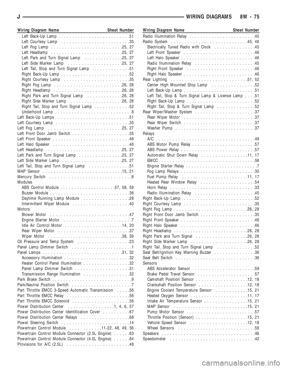
Wiring Diagram Name Sheet Number
Left Back-Up Lamp..........................51
Left Courtesy Lamp.........................35
Left Fog Lamp..........................25, 27
Left Headlamp..........................25, 27
Left Park and Turn Signal Lamp..............25, 27
Left Side Marker Lamp....................25, 27
Left Tail, Stop and Turn Signal Lamp..............51
Right Back-Up Lamp.........................52
Right Courtesy Lamp........................35
Right Fog Lamp.........................26, 28
Right Headlamp.........................26, 28
Right Park and Turn Signal Lamp.............26, 28
Right Side Marker Lamp...................26, 28
Right Tail, Stop and Turn Signal Lamp.............52
Underhood Lamp............................8
Left Back-Up Lamps..........................51
Left Courtesy Lamp...........................35
Left Fog Lamp...........................25, 27
Left Front Door Jamb Switch.....................35
Left Front Speaker............................46
Left Halo Speaker............................46
Left Headlamp............................25, 27
Left Park and Turn Signal Lamp................25, 27
Left Side Marker Lamp......................25, 27
Left Tail, Stop and Turn Signal Lamp...............51
MAP Sensor.............................15, 21
Mercury Switch..............................8
Modules
ABS Control Module....................57, 58, 59
Buzzer Module.............................36
Daytime Running Lamp Module.................28
Intermittent Wiper Module.....................40
Motors
Blower Motor.............................47
Engine Starter Motor.........................7
Idle Air Control Motor.....................14, 20
Rear Wiper Motor..........................37
Wiper Motor...........................38, 39
Oil Pressure and Temp System...................23
Panel Lamp Dimmer Switch......................1
Panel Lamps.............................31, 32
Accessory Illumination........................32
Heater Control Panel Illumination.................32
Panel Lamp Dimmer Switch....................31
Transmission Range Illumination.................32
Park Brake Switch.............................9
Park/Neutral Position Switch......................7
Part Throttle EMCC 3-Speed Automatic Transmission.....56
Part Throttle EMCC Relay.......................56
Part Throttle EMCC Solenoid.....................56
Power Distribution Center.................1,4,6,57
Power Distribution Center Identification Cover..........67
Power Distribution Center Relays..................68
Power Steering Switch.........................14
Powertrain Control Module............11-22, 48, 49, 56
Powertrain Control Module Connector (2.5L Engine)......63
Powertrain Control Module Connector (4.0L Engine)......64
Provisions for A/C (2.5L).......................48Wiring Diagram Name Sheet Number
Radio Illumination Relay........................45
Radio System............................45, 46
Electrically Tuned Radio with Clock...............45
Left Front Speaker..........................46
Left Halo Speaker...........................46
Radio Illumination Relay......................45
Right Front Speaker.........................46
Right Halo Speaker..........................46
Rear Lighting............................51, 52
Center High Mounted Stop Lamp................52
Left Back-Up Lamp..........................51
Left Tail, Stop & Turn Signal Lamp & License Lamp....51
Right Back-Up Lamp.........................52
Right Tail, Stop & Turn Signal Lamp..............52
Rear Wiper/Washer System......................37
Rear Wiper Motor..........................37
Rear Wiper Switch..........................37
Washer Pump.............................37
Relays
A/C ....................................49
ABS Motor Pump Relay.......................57
ABS Power Relay...........................57
Automatic Shut Down Relay.................11, 17
EMCC...................................56
Engine Starter Relay..........................7
Fog Lamp Relays...........................30
Fuel Pump Relay........................11, 17
Heated Rear Window Relay....................54
Horn Relay...............................33
Radio Illumination Relay......................45
Right Back-Up Lamp..........................52
Right Courtesy Lamp..........................35
Right Fog Lamp...........................26, 28
Right Front Door Jamb Switch....................35
Right Front Speaker...........................46
Right Halo Speaker...........................46
Right Headlamp...........................26, 28
Right Park and Turn Signal...................26, 28
Right Side Marker Lamp.....................26, 28
Right Tail, Stop and Turn Signal Lamp..............52
Seat Belt/Ignition Key Warning Buzzer...............36
Seat Belt Switch.............................36
Sensors
ABS Accelerator Sensor.......................59
Brake Pedal Travel Sensor.....................57
Camshaft Position Sensor...................12, 18
Crankshaft Position Sensor..................12, 18
Engine Coolant Temperature Sensor............15, 21
Heated Oxygen Sensor.....................11, 17
Intake Air Temperature Sensor................15, 21
MAP Sensor...........................15, 21
Pump Motor Sensor.........................57
Throttle Position (Sensor)...................15, 21
Vehicle Speed Sensor.....................12, 18
Wheel Sensors............................59
Speakers..................................46
Speedometer...............................42
JWIRING DIAGRAMS 8W - 75
Page 569 of 1784
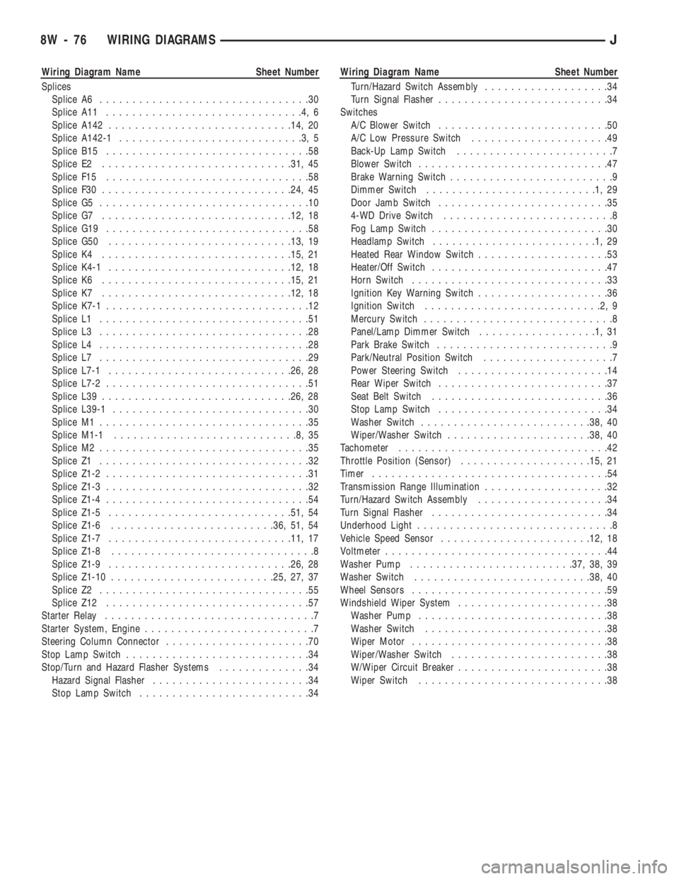
Wiring Diagram Name Sheet Number
Splices
Splice A6................................30
Splice A11..............................4,6
Splice A142............................14, 20
Splice A142-1............................3,5
Splice B15...............................58
Splice E2.............................31, 45
Splice F15...............................58
Splice F30.............................24, 45
Splice G5................................10
Splice G7.............................12, 18
Splice G19...............................58
Splice G50............................13, 19
Splice K4.............................15, 21
Splice K4-1............................12, 18
Splice K6.............................15, 21
Splice K7.............................12, 18
Splice K7-1...............................12
Splice L1................................51
Splice L3................................28
Splice L4................................28
Splice L7................................29
Splice L7-1............................26, 28
Splice L7-2...............................51
Splice L39.............................26, 28
Splice L39-1..............................30
Splice M1................................35
Splice M1-1............................8,35
Splice M2................................35
Splice Z1................................32
Splice Z1-2...............................31
Splice Z1-3...............................32
Splice Z1-4...............................54
Splice Z1-5............................51, 54
Splice Z1-6.........................36, 51, 54
Splice Z1-7............................11, 17
Splice Z1-8...............................8
Splice Z1-9............................26, 28
Splice Z1-10.........................25, 27, 37
Splice Z2................................55
Splice Z12...............................57
Starter Relay................................7
Starter System, Engine..........................7
Steering Column Connector......................70
Stop Lamp Switch............................34
Stop/Turn and Hazard Flasher Systems..............34
Hazard Signal Flasher........................34
Stop Lamp Switch..........................34Wiring Diagram Name Sheet Number
Turn/Hazard Switch Assembly...................34
Turn Signal Flasher..........................34
Switches
A/C Blower Switch..........................50
A/C Low Pressure Switch.....................49
Back-Up Lamp Switch........................7
Blower Switch.............................47
Brake Warning Switch.........................9
Dimmer Switch..........................1,29
Door Jamb Switch..........................35
4-WD Drive Switch..........................8
Fog Lamp Switch...........................30
Headlamp Switch.........................1,29
Heated Rear Window Switch....................53
Heater/Off Switch...........................47
Horn Switch..............................33
Ignition Key Warning Switch....................36
Ignition Switch...........................2,9
Mercury Switch.............................8
Panel/Lamp Dimmer Switch..................1,31
Park Brake Switch...........................9
Park/Neutral Position Switch....................7
Power Steering Switch.......................14
Rear Wiper Switch..........................37
Seat Belt Switch...........................36
Stop Lamp Switch..........................34
Washer Switch..........................38, 40
Wiper/Washer Switch......................38, 40
Tachometer................................42
Throttle Position (Sensor)....................15, 21
Timer....................................54
Transmission Range Illumination...................32
Turn/Hazard Switch Assembly....................34
Turn Signal Flasher...........................34
Underhood Light..............................8
Vehicle Speed Sensor.......................12, 18
Voltmeter..................................44
Washer Pump.........................37, 38, 39
Washer Switch...........................38, 40
Wheel Sensors..............................59
Windshield Wiper System.......................38
Washer Pump.............................38
Washer Switch............................38
Wiper Motor..............................38
Wiper/Washer Switch........................38
W/Wiper Circuit Breaker.......................38
Wiper Switch.............................38
8W - 76 WIRING DIAGRAMSJ
Page 642 of 1784
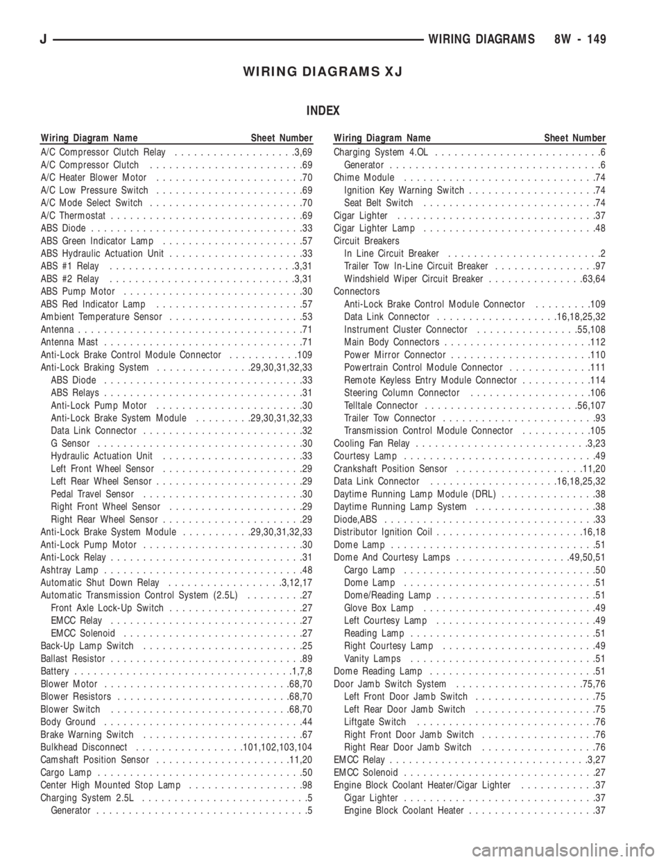
WIRING DIAGRAMS XJ
INDEX
Wiring Diagram Name Sheet Number
A/C Compressor Clutch Relay...................3,69
A/C Compressor Clutch........................69
A/C Heater Blower Motor.......................70
A/C Low Pressure Switch.......................69
A/C Mode Select Switch........................70
A/C Thermostat..............................69
ABS Diode.................................33
ABS Green Indicator Lamp......................57
ABS Hydraulic Actuation Unit.....................33
ABS #1 Relay.............................3,31
ABS #2 Relay.............................3,31
ABS Pump Motor............................30
ABS Red Indicator Lamp.......................57
Ambient Temperature Sensor.....................53
Antenna...................................71
Antenna Mast...............................71
Anti-Lock Brake Control Module Connector...........109
Anti-Lock Braking System...............29,30,31,32,33
ABS Diode...............................33
ABS Relays...............................31
Anti-Lock Pump Motor.......................30
Anti-Lock Brake System Module.........29,30,31,32,33
Data Link Connector.........................32
G Sensor................................30
Hydraulic Actuation Unit......................33
Left Front Wheel Sensor......................29
Left Rear Wheel Sensor.......................29
Pedal Travel Sensor.........................30
Right Front Wheel Sensor.....................29
Right Rear Wheel Sensor......................29
Anti-Lock Brake System Module...........29,30,31,32,33
Anti-Lock Pump Motor.........................30
Anti-Lock Relay..............................31
Ashtray Lamp...............................48
Automatic Shut Down Relay..................3,12,17
Automatic Transmission Control System (2.5L).........27
Front Axle Lock-Up Switch.....................27
EMCC Relay..............................27
EMCC Solenoid............................27
Back-Up Lamp Switch.........................25
Ballast Resistor..............................89
Battery..................................1,7,8
Blower Motor.............................68,70
Blower Resistors...........................68,70
Blower Switch............................68,70
Body Ground...............................44
Brake Warning Switch.........................67
Bulkhead Disconnect.................101,102,103,104
Camshaft Position Sensor.....................11,20
Cargo Lamp................................50
Center High Mounted Stop Lamp..................98
Charging System 2.5L..........................5
Generator.................................5Wiring Diagram Name Sheet Number
Charging System 4.OL..........................6
Generator.................................6
Chime Module..............................74
Ignition Key Warning Switch....................74
Seat Belt Switch...........................74
Cigar Lighter...............................37
Cigar Lighter Lamp...........................48
Circuit Breakers
In Line Circuit Breaker........................2
Trailer Tow In-Line Circuit Breaker................97
Windshield Wiper Circuit Breaker...............63,64
Connectors
Anti-Lock Brake Control Module Connector.........109
Data Link Connector...................16,18,25,32
Instrument Cluster Connector................55,108
Main Body Connectors.......................112
Power Mirror Connector......................110
Powertrain Control Module Connector.............111
Remote Keyless Entry Module Connector...........114
Steering Column Connector...................106
Telltale Connector........................56,107
Trailer Tow Connector........................93
Transmission Control Module Connector...........105
Cooling Fan Relay...........................3,23
Courtesy Lamp..............................49
Crankshaft Position Sensor....................11,20
Data Link Connector....................16,18,25,32
Daytime Running Lamp Module (DRL)...............38
Daytime Running Lamp System...................38
Diode,ABS.................................33
Distributor Ignition Coil.......................16,18
Dome Lamp................................51
Dome And Courtesy Lamps..................49,50,51
Cargo Lamp..............................50
Dome Lamp..............................51
Dome/Reading Lamp.........................51
Glove Box Lamp...........................49
Left Courtesy Lamp.........................49
Reading Lamp.............................51
Right Courtesy Lamp........................49
Vanity Lamps.............................51
Dome Reading Lamp..........................51
Door Jamb Switch System....................75,76
Left Front Door Jamb Switch...................75
Left Rear Door Jamb Switch...................75
Liftgate Switch............................76
Right Front Door Jamb Switch..................76
Right Rear Door Jamb Switch..................76
EMCC Relay...............................3,27
EMCC Solenoid..............................27
Engine Block Coolant Heater/Cigar Lighter............37
Cigar Lighter..............................37
Engine Block Coolant Heater....................37
JWIRING DIAGRAMS 8W - 149