1994 JEEP CHEROKEE relay
[x] Cancel search: relayPage 317 of 1784
stalled, its rotational position can not be changed.
Do not attempt to modify the distributor housing
to get distributor rotation. Distributor position
will have no effect on ignition timing.
All distributors contain an internal oil seal that
prevents oil from entering the distributor housing.
The seal is not serviceable.
For component testing, refer to the Diagnostics/Ser-
vice Procedures section of this group.For removal and installation of this component, re-
fer to the Component Removal/Installation section of
this group.
IGNITION COIL
Battery voltage is supplied to the ignition coil pos-
itive terminal from the ASD relay.
The Powertrain Control Module (PCM) opens and
closes the ignition coil ground circuit for ignition coil
operation.
Base ignition timing is not adjustable.By con-
trolling the coil ground circuit, the PCM is able to
set the base timing and adjust the ignition timing
advance. This is done to meet changing engine oper-
ating conditions.
The ignition coil is not oil filled. The windings are
embedded in an epoxy compound. This provides heat
and vibration resistance that allows the ignition coil
to be mounted on the engine.
The ignition coil is mounted to a bracket on the
side of the engine (Fig. 11).
For component testing, refer to the Diagnostics/Ser-
vice Procedures section of this group.
For removal and installation of this component, re-
fer to the Component Removal/Installation section of
this group.
ENGINE COOLANT TEMPERATURE SENSOR
The engine coolant temperature sensor provides an
input voltage to the Powertrain Control Module
(PCM) relating coolant temperature. The PCM uses
this input, along with inputs from other sensors, to
determine injector pulse width and ignition timing.
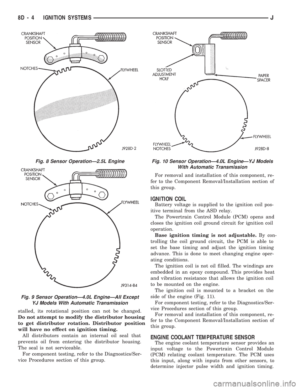
Fig. 8 Sensor OperationÐ2.5L Engine
Fig. 9 Sensor OperationÐ4.0L EngineÐAll Except
YJ Models With Automatic Transmission
Fig. 10 Sensor OperationÐ4.0L EngineÐYJ Models
With Automatic Transmission
8D - 4 IGNITION SYSTEMSJ
Page 321 of 1784

DIAGNOSTICS/SERVICE PROCEDURES
INDEX
page page
Automatic Shut Down (ASD) Relay............ 8
Camshaft Position Sensor Test............... 8
Crankshaft Position Sensor Test.............. 9
Distributor Cap........................... 9
Distributor Rotor......................... 10
DRB Scan Tool.......................... 10
Engine Coolant Temperature Sensor Test...... 12
General Information........................ 8
Ignition Coil............................. 11
Ignition Secondary Circuit Diagnosis.......... 12Ignition Timing........................... 14
Intake Manifold Air Temperature Sensor Test . . . 14
Manifold Absolute Pressure (MAP) Sensor Test . 14
On-Board Diagnostics (OBD)................ 19
Oxygen Sensor Tests..................... 19
Powertrain Control Module (PCM)............ 15
Spark Plug Secondary Cables............... 17
Spark Plugs............................ 16
Throttle Position Sensor Test............... 18
GENERAL INFORMATION
This section of the group, Diagnostics/Service Pro-
cedures, will discuss basic ignition system diagnos-
tics and service adjustments.
For system operation and component identification,
refer to the Component Identification/System Opera-
tion section of this group.
For removal or installation of ignition system com-
ponents, refer to the Component Removal/Installa-
tion section of this group.
For other useful information, refer to On-Board Di-
agnostics in the General Diagnosis sections of Group
14, Fuel System in this manual.
For operation of the DRB Scan Tool, refer to the
appropriate Powertrain Diagnostic Procedures ser-
vice manual.
AUTOMATIC SHUT DOWN (ASD) RELAY
Refer to RelaysÐOperation/Testing in the Group
14, Fuel System section of this service manual.
CAMSHAFT POSITION SENSOR TEST
The camshaft position sensor is located in the dis-
tributor on all engines.
To perform a complete test of this sensor and its
circuitry, refer to the DRB scan tool. Also refer to the
appropriate Powertrain Diagnostics Procedures man-
ual. To test the sensor only, refer to the following:
2.5L OR 4.0L ENGINE
For this test, an analog voltmeter is needed.Do
not remove the distributor connector from the dis-
tributor. Using small paper clips, insert them into
the backside of the distributor wire harness connec-
tor to make contact with the terminals. Be sure that
the connector is not damaged when inserting the pa-
per clips. Attach voltmeter leads to these paper clips.
(1) Connect the positive (+) voltmeter lead into
the sensor output wire. This is at done the distribu-
tor wire harness connector. For wire identification,
refer to Group 8W, Wiring Diagrams.(2) Connect the negative (-) voltmeter lead into the
ground wire. For wire identification, refer to Group
8W, Wiring Diagrams.
(3) Set the voltmeter to the 15 Volt DC scale.
(4) Remove distributor cap. Rotate (crank) engine
with starter until pulse ring (Fig. 1) enters the mag-
netic pickup on camshaft position sensor. Distributor
rotor should be pointed in 9 o'clock position. The
movable pulse ring should now be within the sensor
pickup.
(5) Turn ignition key to ON position. Voltmeter
should read approximately 5.0 volts.
(6) If voltage is not present, check the voltmeter
leads for a good connection.
(7) If voltage is still not present, check for voltage
at the supply wire. For wire identification, refer to
Group 8W, Wiring Diagrams.
Fig. 1 Pulse Ring/Rotor PositionÐTypical
8D - 8 IGNITION SYSTEMSJ
Page 326 of 1784
(4) Using insulated pliers, hold the cable terminal
approximately 12 mm (1/2 in.) from the engine cylin-
der head or block while rotating the engine with the
starter motor. Observe the spark plug cable terminal
for an arc. If steady arcing occurs, it can be expected
that the ignition secondary system is operating cor-
rectly. If steady arcing occurs at the spark plug ca-
bles, but the engine will not start, connect the DRB
scan tool. Refer to the Powertrain Diagnostic Proce-
dures service manual for DRB operation.
FAILURE TO START TEST
To prevent unnecessary diagnostic time and wrong
test results, the previous Checking For Spark test
should be performed prior to this test.
WARNING: SET PARKING BRAKE OR BLOCK THE
DRIVE WHEELS BEFORE PROCEEDING WITH THIS
TEST.
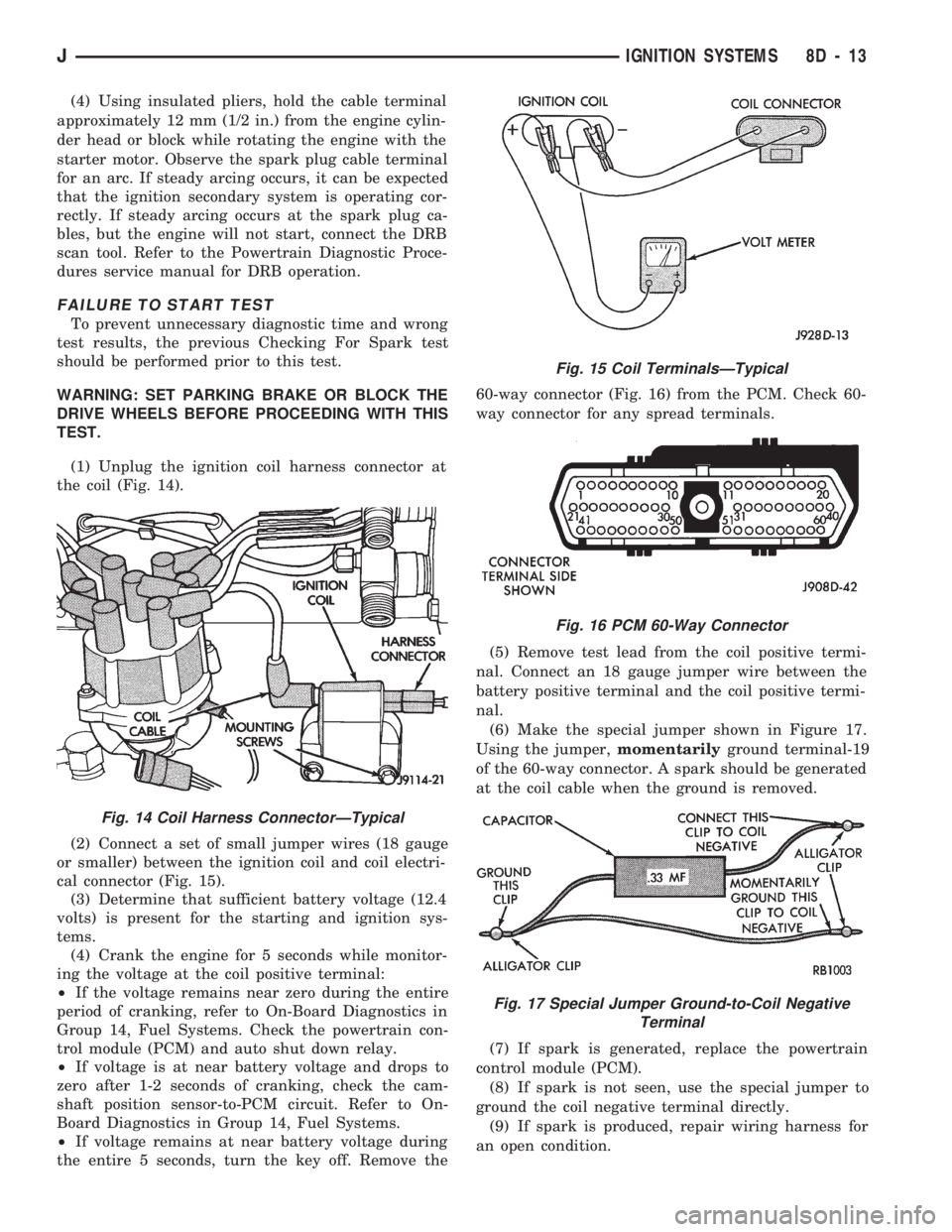
(1) Unplug the ignition coil harness connector at
the coil (Fig. 14).
(2) Connect a set of small jumper wires (18 gauge
or smaller) between the ignition coil and coil electri-
cal connector (Fig. 15).
(3) Determine that sufficient battery voltage (12.4
volts) is present for the starting and ignition sys-
tems.
(4) Crank the engine for 5 seconds while monitor-
ing the voltage at the coil positive terminal:
²If the voltage remains near zero during the entire
period of cranking, refer to On-Board Diagnostics in
Group 14, Fuel Systems. Check the powertrain con-
trol module (PCM) and auto shut down relay.
²If voltage is at near battery voltage and drops to
zero after 1-2 seconds of cranking, check the cam-
shaft position sensor-to-PCM circuit. Refer to On-
Board Diagnostics in Group 14, Fuel Systems.
²If voltage remains at near battery voltage during
the entire 5 seconds, turn the key off. Remove the60-way connector (Fig. 16) from the PCM. Check 60-
way connector for any spread terminals.
(5) Remove test lead from the coil positive termi-
nal. Connect an 18 gauge jumper wire between the
battery positive terminal and the coil positive termi-
nal.
(6) Make the special jumper shown in Figure 17.
Using the jumper,momentarilyground terminal-19
of the 60-way connector. A spark should be generated
at the coil cable when the ground is removed.
(7) If spark is generated, replace the powertrain
control module (PCM).
(8) If spark is not seen, use the special jumper to
ground the coil negative terminal directly.
(9) If spark is produced, repair wiring harness for
an open condition.
Fig. 14 Coil Harness ConnectorÐTypical
Fig. 15 Coil TerminalsÐTypical
Fig. 16 PCM 60-Way Connector
Fig. 17 Special Jumper Ground-to-Coil Negative
Terminal
JIGNITION SYSTEMS 8D - 13
Page 333 of 1784
COMPONENT REMOVAL/INSTALLATION
INDEX
page page
Automatic Shut Down (ASD) Relay........... 20
Camshaft Position Sensor.................. 20
Crankshaft Position Sensor................. 21
Distributor.............................. 23
Engine Coolant Temperature Sensor.......... 22
General Information....................... 20
Ignition Coil............................. 26Intake Manifold Air Temperature Sensor....... 27
Manifold Absolute Pressure (MAP) Sensor..... 27
Oxygen (O2S) Sensor..................... 28
Powertrain Control Module (PCM)............ 28
Spark Plug Secondary Cables............... 29
Spark Plugs............................ 28
Throttle Position Sensor (TPS).............. 29
GENERAL INFORMATION
This section of the group, Component Removal/In-
stallation, will discuss the removal and installation
of ignition system components.
For basic ignition system diagnostics and service
adjustments, refer to the Diagnostics/Service Proce-
dures section of this group.
For system operation and component identification,
refer to the Component Identification/System Opera-
tion section of this group.
AUTOMATIC SHUT DOWN (ASD) RELAY
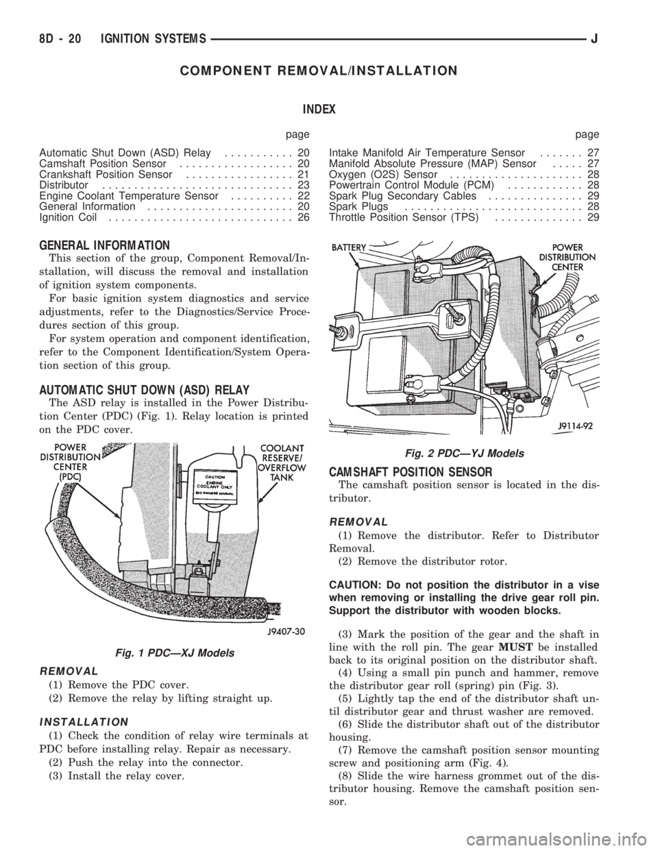
The ASD relay is installed in the Power Distribu-
tion Center (PDC) (Fig. 1). Relay location is printed
on the PDC cover.
REMOVAL
(1) Remove the PDC cover.
(2) Remove the relay by lifting straight up.
INSTALLATION
(1) Check the condition of relay wire terminals at
PDC before installing relay. Repair as necessary.
(2) Push the relay into the connector.
(3) Install the relay cover.
CAMSHAFT POSITION SENSOR
The camshaft position sensor is located in the dis-
tributor.
REMOVAL
(1) Remove the distributor. Refer to Distributor
Removal.
(2) Remove the distributor rotor.
CAUTION: Do not position the distributor in a vise
when removing or installing the drive gear roll pin.
Support the distributor with wooden blocks.
(3) Mark the position of the gear and the shaft in
line with the roll pin. The gearMUSTbe installed
back to its original position on the distributor shaft.
(4) Using a small pin punch and hammer, remove
the distributor gear roll (spring) pin (Fig. 3).
(5) Lightly tap the end of the distributor shaft un-
til distributor gear and thrust washer are removed.
(6) Slide the distributor shaft out of the distributor
housing.
(7) Remove the camshaft position sensor mounting
screw and positioning arm (Fig. 4).
(8) Slide the wire harness grommet out of the dis-
tributor housing. Remove the camshaft position sen-
sor.
Fig. 1 PDCÐXJ Models
Fig. 2 PDCÐYJ Models
8D - 20 IGNITION SYSTEMSJ
Page 351 of 1784

(3) Connect a jumper between terminal A and B on
the body half of the fuel gauge sender connector. The
gauge should move to F. If gauge is OK, replace
sender. If not, go to step 4.
(4) Measure resistance of sender. Meter should
read 105 to 5 ohms. If OK, go to step 5. If not, re-
place sender.
(5) Check for an open between sender connector
and gauge. If OK, replace gauge. If not, repair open
to gauge.
LOW FUEL WARNING INOPERATIVE
(1) Turn ignition switch to ON.
(2) Disconnect terminal B1 of the instrument clus-
ter connector. Wait at least 10 seconds. Lamp (LED)
should light. If OK, replace sender. If not, replace
low fuel warning module.
UPSHIFT INDICATOR INOPERATIVE
(1) Turn ignition switch to ON.
(2) Ground pin 7 of connector B. Lamp should
light. If not, replace bulb. If OK, continue with
step 3.
(3) Turn ignition switch to OFF. Check for conti-
nuity between connector B pin 2 and pin 54 of the
Powertrain Control Module. If OK, replace PCM. If
not, repair open.
BRAKE INDICATOR INOPERATIVE
(1) Turn ignition switch to ON. Apply parking
brake, brake warning switch connector unplugged.
(2) Jumper brake warning switch connector termi-
nal B to ground. Lamp should light. If bulb is OK,
repair open to indicator.
(3) Turn ignition switch to OFF. Measure resis-
tance between brake warning switch connector ter-
minal A and ground. Meter should read zero ohms. If
OK, check switch and/or brake system. If not, repair
open to park brake switch ground.
4WD INDICATOR INOPERATIVE
(1) Apply parking brake, start engine, vehicle in
4WD Lock or 4WD.
(2) Unplug switch and touch harness side of wire
to ground. Lamp should light. If OK, check switch
operation, replace if bad. If bulb is OK, repair open
to indicator.
LOW WASHER INDICATOR INOPERATIVE
(1) Turn ignition switch to ON.
(2) Jumper 12 volts to fluid level switch connector
terminal B. Lamp should light. If not, go to step 3.
(3) Measure resistance between terminal B and
ground. Meter should read zero ohms. If not, repair
open to bulb. If OK, go to step 4.
(4) Measure voltage at fluid level switch connector
terminal A. Meter should read battery voltage. If
OK, replace switch. If not, repair open to fuse.
MALFUNCTION INDICATOR LAMP (CHECK ENGINE)
(1) Turn ignition switch to ON.
(2) Jumper Powertrain Control Module terminal 2
to ground. Lamp should light. If bulb is OK, check
for open to instrument cluster connector terminal 2.
ANTI-LOCK INDICATOR
(1) Turn ignition switch to ON.
(2) Jumper instrument cluster connector terminal
6 to ground. Lamp should light. If bulb is OK, check
wiring for an open to module. Refer to Group 5 -
Brakes.
SEAT BELT INDICATOR
Jumper instrument cluster connector terminal 15
to 12 volts. Lamp should light. If not, replace bulb. If
OK, check wiring for an open to buzzer module. Re-
fer to Group 8U - Chime/Buzzer Warning Systems.
RADIO/CLOCK ILLUMINATION
With the ignition switch in ACCESSORY or ON,
power comes from the radio fuse. It then goes
through the normally closed contacts of the radio il-
lumination relay to the radio at connector terminal
11.
Pulling the headlamp switch to ON energizes the
radio illumination relay. This closes the normally
open contacts of the relay, and the brightness for the
radio display is controlled by the headlamp switch
rheostat. The back-lighting for the radio is also con-
trolled by the headlamp rheostat through radio con-
nector terminal 10.
Refer to Group 8F - Audio Systems, for radio illu-
mination relay diagnosis.
INSTRUMENT PANEL LAMPS
Voltage is supplied at all times from the 40 amp
Maxi fuse (located in the Power Distribution Center)
through the park lamps fuse to the headlamp switch.
The circuit continues through the instrument lamps
fuse to the individual instrument panel lamps to
ground. Lamp brightness is controlled by turning the
headlamp switch knob.
DIAGNOSIS
(1) Turn parking lamps ON.
(2) Check park lamps fuse. Replace as required.
(3) Check instrument lamps fuse. Replace as re-
quired.
(4) Measure voltage at battery side of instrument
lamps fuse with rheostat turned counterclockwise to
clockwise (LO to HI). Meter should read zero volts to
battery voltage. If not, replace headlamp switch.
(5) Measure resistance at ground side of instru-
ment lamps fuse with parking lamps OFF. Meter
should read almost zero ohms (except bulb filament).
If not, repair open to ground. If zero ohms, 12 volt
supply wire from fuse is shorted to ground, repair short.
8E - 4 XJ INSTRUMENT PANEL AND GAUGESJ
Page 376 of 1784
AUDIO SYSTEMS
CONTENTS
page page
GENERAL INFORMATION.................. 1
RADIO ANTENNA........................ 8XJ SERVICE PROCEDURES................ 4
YJ SERVICE PROCEDURES................ 6
GENERAL INFORMATION
DESCRIPTION
Each radio receives ignition feed from an ignition
switch controlled fuse. There is an additional in-line
fuse in the back of the radio chassis. The in-line fuse
will blow in the event an internal short occurs.
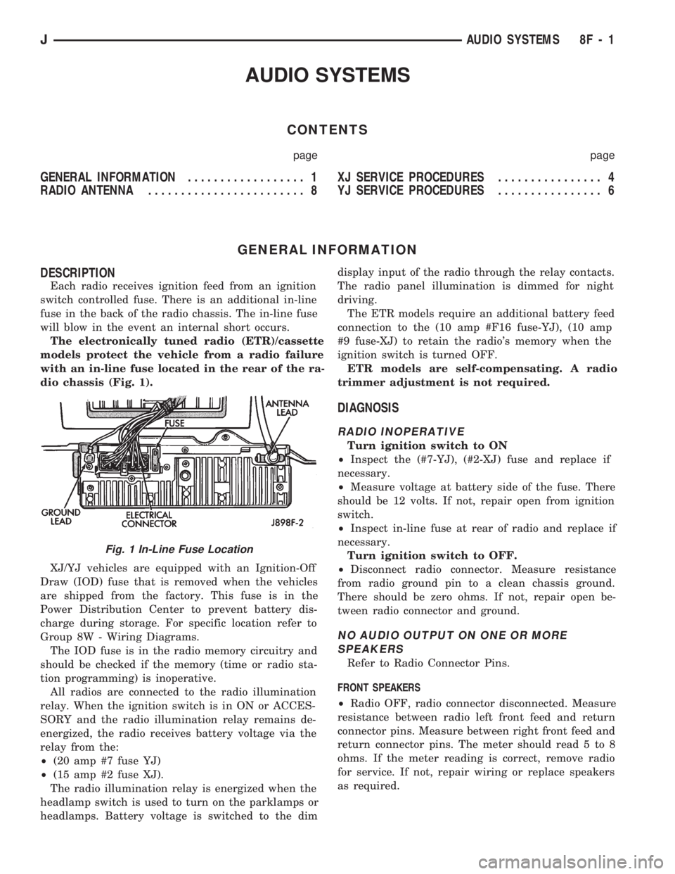
The electronically tuned radio (ETR)/cassette
models protect the vehicle from a radio failure
with an in-line fuse located in the rear of the ra-
dio chassis (Fig. 1).
XJ/YJ vehicles are equipped with an Ignition-Off
Draw (IOD) fuse that is removed when the vehicles
are shipped from the factory. This fuse is in the
Power Distribution Center to prevent battery dis-
charge during storage. For specific location refer to
Group 8W - Wiring Diagrams.
The IOD fuse is in the radio memory circuitry and
should be checked if the memory (time or radio sta-
tion programming) is inoperative.
All radios are connected to the radio illumination
relay. When the ignition switch is in ON or ACCES-
SORY and the radio illumination relay remains de-
energized, the radio receives battery voltage via the
relay from the:
²(20 amp #7 fuse YJ)
²(15 amp #2 fuse XJ).
The radio illumination relay is energized when the
headlamp switch is used to turn on the parklamps or
headlamps. Battery voltage is switched to the dimdisplay input of the radio through the relay contacts.
The radio panel illumination is dimmed for night
driving.
The ETR models require an additional battery feed
connection to the (10 amp #F16 fuse-YJ), (10 amp
#9 fuse-XJ) to retain the radio's memory when the
ignition switch is turned OFF.
ETR models are self-compensating. A radio
trimmer adjustment is not required.
DIAGNOSIS
RADIO INOPERATIVE
Turn ignition switch to ON
²Inspect the (#7-YJ), (#2-XJ) fuse and replace if
necessary.
²Measure voltage at battery side of the fuse. There
should be 12 volts. If not, repair open from ignition
switch.
²Inspect in-line fuse at rear of radio and replace if
necessary.
Turn ignition switch to OFF.
²Disconnect radio connector. Measure resistance
from radio ground pin to a clean chassis ground.
There should be zero ohms. If not, repair open be-
tween radio connector and ground.
NO AUDIO OUTPUT ON ONE OR MORE
SPEAKERS
Refer to Radio Connector Pins.
FRONT SPEAKERS
²Radio OFF, radio connector disconnected. Measure
resistance between radio left front feed and return
connector pins. Measure between right front feed and
return connector pins. The meter should read 5 to 8
ohms. If the meter reading is correct, remove radio
for service. If not, repair wiring or replace speakers
as required.
Fig. 1 In-Line Fuse Location
JAUDIO SYSTEMS 8F - 1
Page 377 of 1784
REAR SPEAKERS
²Radio OFF, radio connector disconnected. Measure
resistance between radio left rear feed and return
connector pins. Measure between right rear feed and
return connector pins. The meter should read 5 to 8
ohms. If meter reading is correct remove radio for
service. If not, repair wiring or replace speakers as
required.
DISTORTED AUDIO OUTPUT ON ONE OR
MORE SPEAKERS
²With the radio ON, substitute known good speaker
or speakers. If the sound is still distorted, remove ra-
dio for service.
WEAK OR NO RECEPTION; NO AUDIO
OUTPUT; BACKGROUND NOISE PRESENT
Ignition switch in ON, radio ON.
²Inspect antenna cable and connector at radio and
tighten or repair as necessary.
²Unplug coax cable and connectors from radio. Mea-
sure resistance from center conductor to coaxial
shield. The meter should read infinite resistance
(open). If it does not, replace antenna assembly.
²Measure resistance of antenna mast to tip of cen-
ter conductor at radio end of cable. The meter should
read 0 to 0.5 ohms. If it does not, replace lead-in ca-
ble or antenna assembly.
²Measure resistance from coaxial shield to chassis
ground (vehicle body). The meter should read zero
ohms. If it does not, ground antenna base to vehicle
body, or replace antenna assembly as required
For all problems with no or low audio output
not resolved by these tests, remove radio for ser-
vice.
MEMORY DOES NOT OPERATE
²Inspect (F16 in Power Distribution Center-YJ),
(#9 in Fuse Panel-XJ) fuse and replace if necessary.
²Measure voltage at battery side of previously ref-
erenced fuse. There should be 12 volts at battery side
of fuse. If not, check the Maxi fuse.
Refer to Group 8W - Wiring Diagrams.
²Measure voltage at radio connector pin 4. There
should be 12 volts. If meter reading is correct, re-
move radio for service. If not, repair open from fuse.
RADIO DISPLAY ILLUMINATION (PARKLAMPS
AND HEADLAMPS OPERATING NORMALLY)
Headlamp switch OFF, radio ON.
²Measure voltage at radio connector pin 10. There
should be 12 volts. If not, go to next step. If OK, re-
move radio for repair by authorized outlet.
²Measure voltage at illumination relay pin 3. There
should be 12 volts. If 12 volts present, replace illumi-
nation relay. If not, repair open in circuit.RADIO DISPLAY ILLUMINATION DIMMING CIRCUIT
Turn headlamp switch to PARKLAMPS for
voltage tests; turn headlamp switch to OFF for
resistance tests.
²Separate relay connector from radio illumination
relay. Measure resistance from relay connector pin 2
to a clean chassis ground. The meter should read
zero ohms. If not, repair open between relay connec-
tor and ground.
²Measure voltage at radio illumination relay pin 5.
There should be battery voltage. If not repair open
from headlamp switch.
²Measure voltage at radio illumination relay pin 4.
Voltage should vary with dimmer switch. If OK, go
to next step. If not, repair open circuit between pin 4
and interior lamp rheostat.
²Measure voltage at radio illumination relay pin
10. Voltage should vary with dimmer switch. If OK,
remove radio for repair by authorized outlet. If not,
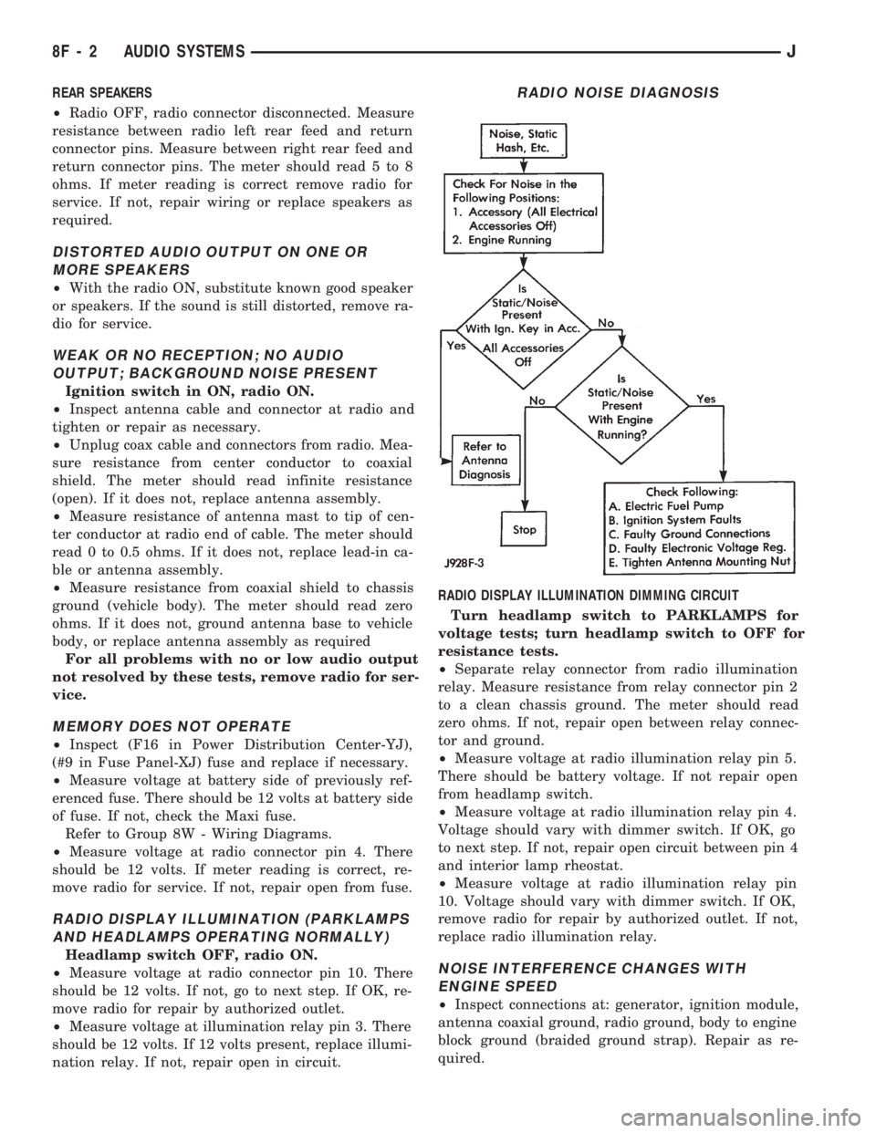
replace radio illumination relay.NOISE INTERFERENCE CHANGES WITH
ENGINE SPEED
²Inspect connections at: generator, ignition module,
antenna coaxial ground, radio ground, body to engine
block ground (braided ground strap). Repair as re-
quired.
RADIO NOISE DIAGNOSIS
8F - 2 AUDIO SYSTEMSJ
Page 378 of 1784

²Inspect secondary ignition system components:
wire routing and condition, distributor cap and rotor,
ignition coil, spark plugs. Reroute or replace as re-
quired.RADIO ILLUMINATION RELAY
XJ
The radio illumination relay is in the relay center.
The relay center is located on the lower instrument
panel trim cover, right of the steering column
(Fig. 2).
YJ
The radio illumination relay is taped to the har-
ness above the radio.
RADIO CONNECTOR PINS
Fig. 2 Radio Illumination Relay
JAUDIO SYSTEMS 8F - 3