1994 JEEP CHEROKEE relay
[x] Cancel search: relayPage 262 of 1784
through the relay. When coolant temperature is be-
low 88ÉC (190ÉF), the PCM opens the ground path to
the relay. This will prevent the cooling fan from be-
ing energized.
Whenever the air conditioning is used, the PCM
engages the auxiliary cooling fan. It provides a
ground path to the cooling fan relay.
DIAGNOSIS
The powertrain control module (PCM) will enter a
diagnostic trouble code (DTC) number 35 in memory
if it detects a problem in the auxiliary cooling fan re-
lay or circuit. This will be read as a flashing signal
at the instrument panel mounted Malfunction Indica-
tor Lamp (formerly referred to as the Check Engine
Lamp). Refer to On-Board Diagnostics in Group 14,
Fuel Systems for information on accessing a DTC.
The DTC can also be accessed through the DRB
scan tool. Refer to the appropriate Powertrain Diag-
nostic Procedures manual for diagnostic information
and operation of the DRB scan tool.
REMOVAL
The auxiliary fan is attached to the radiator upper
crossmember behind the radiator.
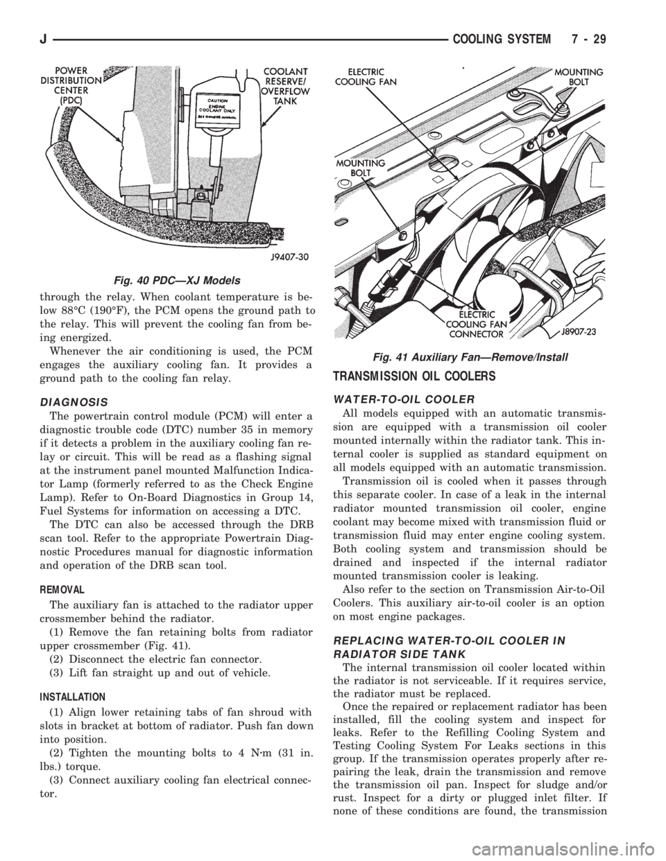
(1) Remove the fan retaining bolts from radiator
upper crossmember (Fig. 41).
(2) Disconnect the electric fan connector.
(3) Lift fan straight up and out of vehicle.
INSTALLATION
(1) Align lower retaining tabs of fan shroud with
slots in bracket at bottom of radiator. Push fan down
into position.
(2) Tighten the mounting bolts to 4 Nzm (31 in.
lbs.) torque.
(3) Connect auxiliary cooling fan electrical connec-
tor.
TRANSMISSION OIL COOLERS
WATER-TO-OIL COOLER
All models equipped with an automatic transmis-
sion are equipped with a transmission oil cooler
mounted internally within the radiator tank. This in-
ternal cooler is supplied as standard equipment on
all models equipped with an automatic transmission.
Transmission oil is cooled when it passes through
this separate cooler. In case of a leak in the internal
radiator mounted transmission oil cooler, engine
coolant may become mixed with transmission fluid or
transmission fluid may enter engine cooling system.
Both cooling system and transmission should be
drained and inspected if the internal radiator
mounted transmission cooler is leaking.
Also refer to the section on Transmission Air-to-Oil
Coolers. This auxiliary air-to-oil cooler is an option
on most engine packages.
REPLACING WATER-TO-OIL COOLER IN
RADIATOR SIDE TANK
The internal transmission oil cooler located within
the radiator is not serviceable. If it requires service,
the radiator must be replaced.
Once the repaired or replacement radiator has been
installed, fill the cooling system and inspect for
leaks. Refer to the Refilling Cooling System and
Testing Cooling System For Leaks sections in this
group. If the transmission operates properly after re-
pairing the leak, drain the transmission and remove
the transmission oil pan. Inspect for sludge and/or
rust. Inspect for a dirty or plugged inlet filter. If
none of these conditions are found, the transmission
Fig. 40 PDCÐXJ Models
Fig. 41 Auxiliary FanÐRemove/Install
JCOOLING SYSTEM 7 - 29
Page 282 of 1784
ENGINE STARTER MOTOR TEST PROCEDURES ON VEHICLE
INDEX
page page
2.5L Starter Motor Noise Diagnosis........... 13
General Information........................ 9
Starter Control Circuit Tests................ 11
Starter Feed Circuit Tests - (Voltage Drop Method).9
Starter System Diagnostic Inspections.......... 9
Starting System Cold Cranking Test........... 9
GENERAL INFORMATION
The starting system consists of an:
²ignition switch
²starter relay
²park/neutral position switch (automatic transmis-
sion)
²wiring harness
²battery
²starter motor with an integral solenoid.
These components form 2 separate circuits. A high
amperage circuit that feeds the starter motor up to
300+ amps, and a control circuit that operates on
less than 20 amps.
STARTER SYSTEM DIAGNOSTIC INSPECTIONS
Before removing any unit from the starter motor
system for repair, perform the following inspections:
BATTERY INSPECTION
To determine condition of the battery, perform the
testing procedure outlined in Battery Test Proce-
dures.
WIRING INSPECTION
Inspect wiring for damage. Inspect all connections
at the starter motor solenoid, park/neutral position
switch (if equipped), back-up lamp switch connector,
ignition switch, starter relay, and battery (including
all ground connections). Clean and tighten all con-
nections as required.
SOLENOID, RELAY AND IGNITION SWITCH
INSPECTION
Inspect the solenoid, relay and switch to determine
their condition. Also, if equipped with automatic
transmission, inspect condition of the park/neutral
position switch. Testing information can be found in
the following pages.
STARTING SYSTEM COLD CRANKING TEST
(1) Battery must first pass load and voltage drop
tests and be fully charged before proceeding. Refer to
Battery Test Procedures.(2) Connect a suitable volt-ampere tester to the
battery terminals (Fig. 1). Refer to the operating in-
structions provided with the tester being used.
(3) Fully engage parking brake, place manual
transmission in NEUTRAL, automatic transmission
in PARK.
(4) Verify that all lamps and accessories are OFF.
(5) Remove coil secondary cable from distributor
and connect to ground.
(6) Rotate and hold the ignition switch in the
START position. Note cranking voltage and amper-
age.
(a) If voltage reads above 9.6 volts and amperage
draw reads above specifications, go to Starter Feed
Circuit Tests.
(b) If voltage reads 12.5 volts or greater and am-
perage reads below specifications, go to Starter
Control Circuit Tests.
A cold engine will increase starter motor cur-
rent and reduce battery voltage.
STARTER FEED CIRCUIT TESTS - (VOLTAGE DROP
METHOD)
The voltage drop tests will determine if there is ex-
cessive resistance in the high current circuit. When
performing these tests, it is important that the volt-
meter be connected to the terminals that the cables
are connected to, instead of to the cables themselves.
For example, when testing between the battery and
solenoid, touch the voltmeter test probes to the bat-
tery post and the solenoid threaded stud. The follow-
ing operation will require a voltmeter, accurate to
1/10 of a volt.
Before performing the tests, assure the following
procedures are accomplished:
²remove coil secondary cable from distributor and
connect to ground
²transmission in NEUTRAL (manual transmission)
or PARK (automatic transmission)
²parking brake applied
²battery is fully charged (refer to Battery Test Pro-
cedures).
JBATTERY/STARTING/CHARGING SYSTEMS DIAGNOSTICS 8A - 9
Page 284 of 1784
contact at battery cable to solenoid connection. If
reading is still above 0.2 volt, replace positive bat-
tery cable.
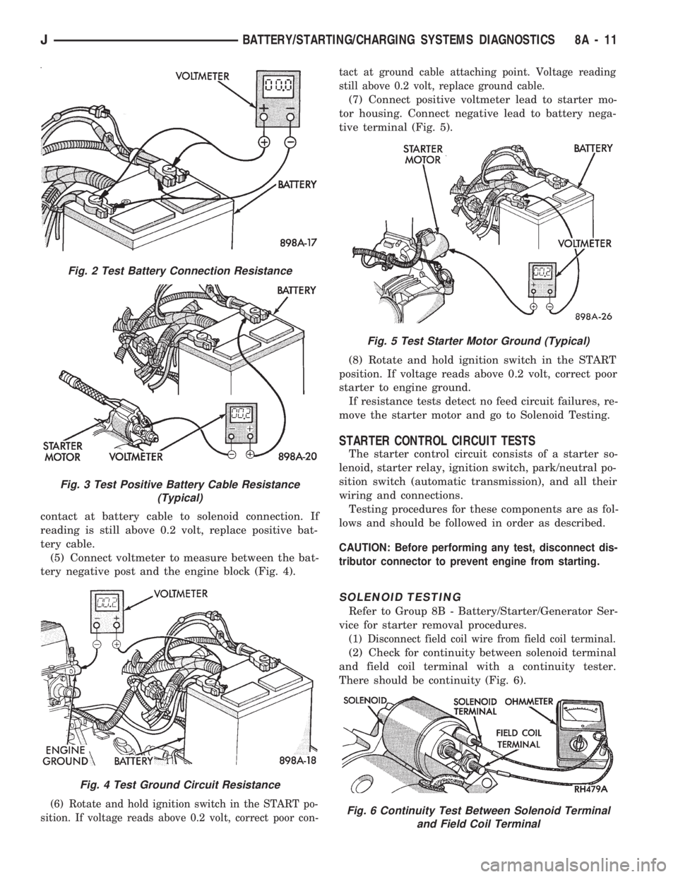
(5) Connect voltmeter to measure between the bat-
tery negative post and the engine block (Fig. 4).
(6) Rotate and hold ignition switch in the START po-
sition. If voltage reads above 0.2 volt, correct poor con-tact at ground cable attaching point. Voltage reading
still above 0.2 volt, replace ground cable.
(7) Connect positive voltmeter lead to starter mo-
tor housing. Connect negative lead to battery nega-
tive terminal (Fig. 5).
(8) Rotate and hold ignition switch in the START
position. If voltage reads above 0.2 volt, correct poor
starter to engine ground.
If resistance tests detect no feed circuit failures, re-
move the starter motor and go to Solenoid Testing.
STARTER CONTROL CIRCUIT TESTS
The starter control circuit consists of a starter so-
lenoid, starter relay, ignition switch, park/neutral po-
sition switch (automatic transmission), and all their
wiring and connections.
Testing procedures for these components are as fol-
lows and should be followed in order as described.
CAUTION: Before performing any test, disconnect dis-
tributor connector to prevent engine from starting.
SOLENOID TESTING
Refer to Group 8B - Battery/Starter/Generator Ser-
vice for starter removal procedures.
(1) Disconnect field coil wire from field coil terminal.
(2) Check for continuity between solenoid terminal
and field coil terminal with a continuity tester.
There should be continuity (Fig. 6).
Fig. 2 Test Battery Connection Resistance
Fig. 3 Test Positive Battery Cable Resistance
(Typical)
Fig. 4 Test Ground Circuit Resistance
Fig. 5 Test Starter Motor Ground (Typical)
Fig. 6 Continuity Test Between Solenoid Terminal
and Field Coil Terminal
JBATTERY/STARTING/CHARGING SYSTEMS DIAGNOSTICS 8A - 11
Page 285 of 1784
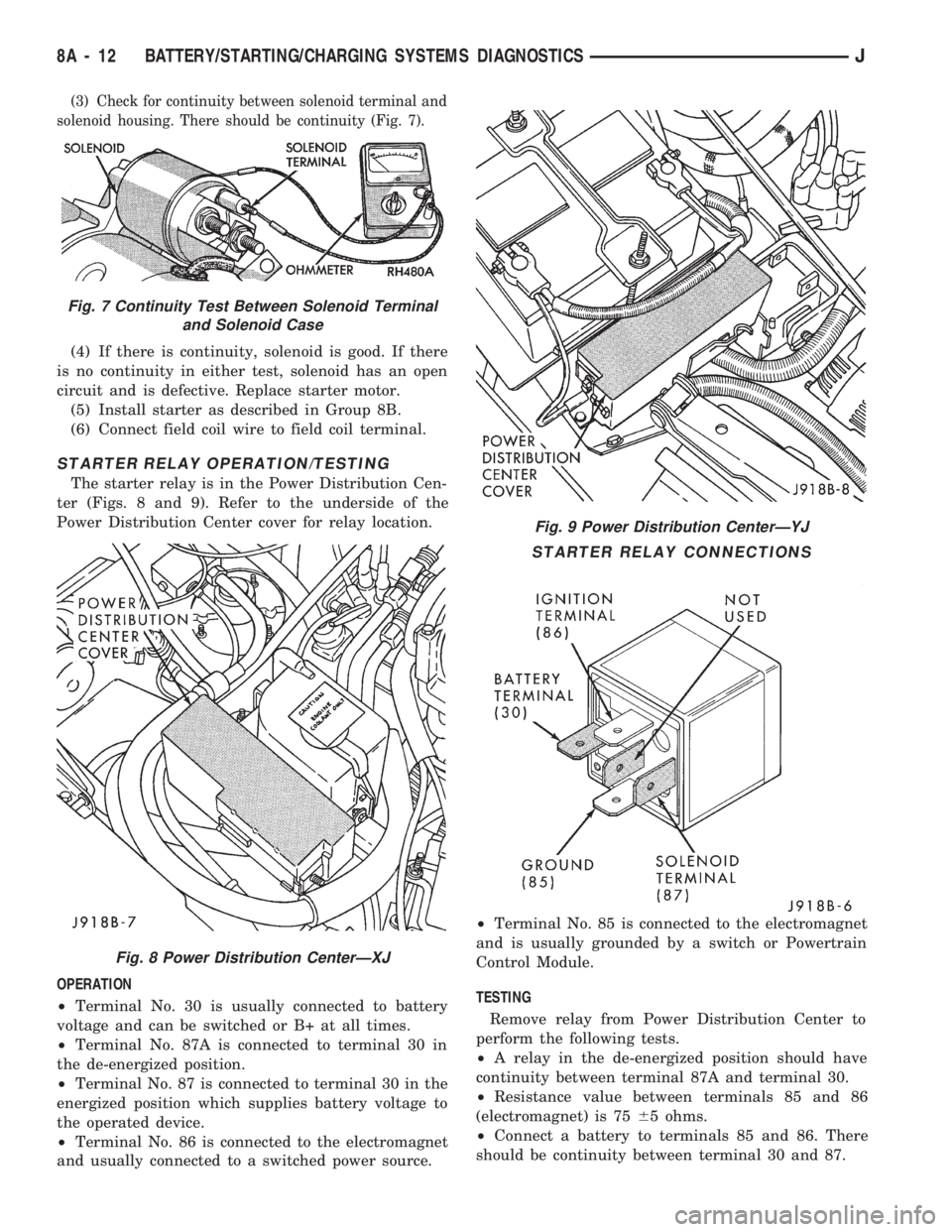
(3) Check for continuity between solenoid terminal and
solenoid housing. There should be continuity (Fig. 7).
(4) If there is continuity, solenoid is good. If there
is no continuity in either test, solenoid has an open
circuit and is defective. Replace starter motor.
(5) Install starter as described in Group 8B.
(6) Connect field coil wire to field coil terminal.
STARTER RELAY OPERATION/TESTING
The starter relay is in the Power Distribution Cen-
ter (Figs. 8 and 9). Refer to the underside of the
Power Distribution Center cover for relay location.
OPERATION
²Terminal No. 30 is usually connected to battery
voltage and can be switched or B+ at all times.
²Terminal No. 87A is connected to terminal 30 in
the de-energized position.
²Terminal No. 87 is connected to terminal 30 in the
energized position which supplies battery voltage to
the operated device.
²Terminal No. 86 is connected to the electromagnet
and usually connected to a switched power source.²Terminal No. 85 is connected to the electromagnet
and is usually grounded by a switch or Powertrain
Control Module.
TESTING
Remove relay from Power Distribution Center to
perform the following tests.
²A relay in the de-energized position should have
continuity between terminal 87A and terminal 30.
²Resistance value between terminals 85 and 86
(electromagnet) is 7565 ohms.
²Connect a battery to terminals 85 and 86. There
should be continuity between terminal 30 and 87.
Fig. 9 Power Distribution CenterÐYJ
STARTER RELAY CONNECTIONS
Fig. 7 Continuity Test Between Solenoid Terminal
and Solenoid Case
Fig. 8 Power Distribution CenterÐXJ
8A - 12 BATTERY/STARTING/CHARGING SYSTEMS DIAGNOSTICSJ
Page 286 of 1784
IGNITION SWITCH TEST
After testing starter solenoid and relay and they
check out OK, trouble is probably with ignition
switch or its wiring.
Check all wiring for opens and shorts, and connec-
tions for being loose or corroded.
PARK/NEUTRAL POSITION SWITCH
Refer to Group 21 - Transmissions for diagnostic
information.
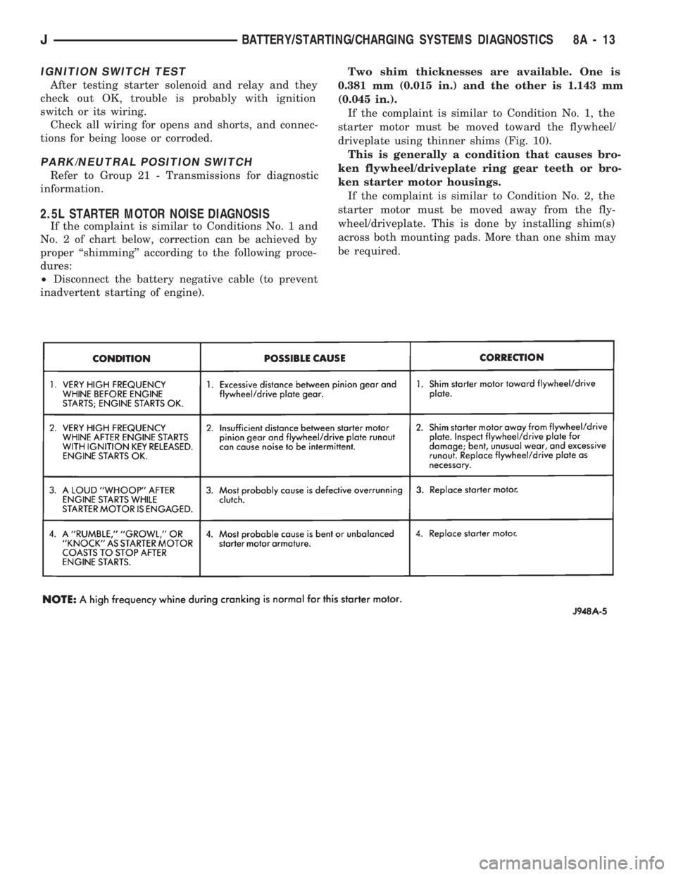
2.5L STARTER MOTOR NOISE DIAGNOSIS
If the complaint is similar to Conditions No. 1 and
No. 2 of chart below, correction can be achieved by
proper ``shimming'' according to the following proce-
dures:
²Disconnect the battery negative cable (to prevent
inadvertent starting of engine).Two shim thicknesses are available. One is
0.381 mm (0.015 in.) and the other is 1.143 mm
(0.045 in.).
If the complaint is similar to Condition No. 1, the
starter motor must be moved toward the flywheel/
driveplate using thinner shims (Fig. 10).
This is generally a condition that causes bro-
ken flywheel/driveplate ring gear teeth or bro-
ken starter motor housings.
If the complaint is similar to Condition No. 2, the
starter motor must be moved away from the fly-
wheel/driveplate. This is done by installing shim(s)
across both mounting pads. More than one shim may
be required.
JBATTERY/STARTING/CHARGING SYSTEMS DIAGNOSTICS 8A - 13
Page 288 of 1784

OPERATIONAL CHECK WITH VOLTMETER
When the ignition switch is turned to the ON po-
sition, battery potential will register on the voltme-
ter. During engine cranking a lower voltage will
appear on the meter. With the engine running, a
voltage reading higher than the first reading (igni-
tion in ON) should register.
DIAGNOSTIC PROCEDURES
If the indicator operates abnormally, or if an un-
dercharged or overcharged battery condition occurs,
the following procedures may be used to diagnose the
charging system.
Remember that an undercharged battery is often
caused by:
²accessories being left on overnight
²or by a defective switch which allows a bulb, such
as a liftgate or glove box light, to stay on (refer to
Ignition Off Draw Diagnosis).
VISUAL INSPECTION
²Inspect condition of battery cable terminals, bat-
tery posts, connections at engine block, starter motor
solenoid and relay. They should be clean and tight.
Repair as required.
²Inspect all fuses in the fuse block for tightness in
receptacles. They should be properly installed and
tight. Repair or replace as required.²Inspect the electrolyte level in the battery and add
water if necessary.
²Inspect generator mounting bolts for tightness. Re-
place or torque bolt as required. Refer to Torque
Specifications in Battery/Starter/Generator Service.
²Inspect generator drive belt condition and tension.
Tension or replace belt as required. Refer to Belt
Tension Specifications in Battery/Starter/Generator
Service.
²Inspect connection at generator B+ output. It
should be clean and tight. Repair as required.
GENERATOR OUTPUT WIRE RESISTANCE
TEST
Generator output wire resistance test will show
amount of voltage drop across generator output wire
between generator battery terminal and battery pos-
itive post.
PREPARATION
(1) Before starting test make sure vehicle has a
fully charged battery. Test and procedures on how to
check for a fully charged battery are shown in Bat-
tery Test Procedures.
(2) Turn OFF ignition switch.
(3) Disconnect negative cable from battery.
(4) Disconnect generator output wire from genera-
tor output battery terminal.
Fig. 2 Generator Output Wire Resistance Test (Typical)
JBATTERY/STARTING/CHARGING SYSTEMS DIAGNOSTICS 8A - 15
Page 297 of 1784

ENGINE STARTER MOTOR SERVICE PROCEDURES
INDEX
page page
2.5L Starter General Information.............. 4
2.5L Starter Motor Removal/Installation......... 5
4.0L Starter General Information.............. 6
4.0L Starter Motor Removal/Installation......... 6General Information........................ 4
Park/Neutral Position Switch................. 6
Starter Relay Replacement.................. 4
GENERAL INFORMATION
This section will cover the starting system compo-
nent service procedures only. For diagnostic proce-
dures, refer to Group 8A - Battery/Starting/Charging
Systems Diagnostics.
Starting system components: battery, starter mo-
tor, starter relay, starter solenoid, ignition switch,
connecting wires and battery cables. A park/neutral
position switch is used with automatic transmissions.
STARTER RELAY REPLACEMENT
The starter relay is located in the Power Distribu-
tion Center (Figs. 1 and 2). Refer to underside of
Power Distribution Center cover for relay location.
(1) Disconnect negative cable from battery.
(2) Replace relay.
(3) Connect negative cable to battery.
(4) Test relay operation.
2.5L STARTER GENERAL INFORMATION
The 2.5L engine starter motor incorporates several
features to create an efficient, lightweight unit.
A planetary gear system (intermediate transmis-
sion) between the electric motor and pinion shaftmakes it possible to reduce the dimensions of the
starter. This also makes it possible to obtain a higher
rotational speed to produce the same torque at the
pinion.
The permanent magnet field consists of six two-
component high strength magnets. The magnets are
aligned according to their polarity and are perma-
nently fixed in the starter frame.
The brush holder plate consists of a plastic base-
plate with four tubular brush holders.
This unit is highly sensitive to hammering, shocks
and external pressure.
CAUTION: The starter motor MUST NOT BE
CLAMPED in a vise by the starter frame. Doing so
may damage the magnets. It may be clamped by the
mounting flange ONLY.
CAUTION: Do not connect starter motor incorrectly
when tests are being performed. The magnets may
be damaged and rendered unserviceable.
²Ensure cleanliness when performing repairs.
Fig. 1 Power Distribution CenterÐXJ
Fig. 2 Power Distribution CenterÐYJ
8B - 4 BATTERY/STARTER/GENERATOR SERVICEJ
Page 314 of 1784

IGNITION SYSTEMS
CONTENTS
page page
COMPONENT IDENTIFICATION/SYSTEM
OPERATION.......................... 1
COMPONENT REMOVAL/INSTALLATION..... 20DIAGNOSTICS/SERVICE PROCEDURES....... 8
IGNITION SWITCH...................... 30
SPECIFICATIONS....................... 33
COMPONENT IDENTIFICATION/SYSTEM OPERATION
INDEX
page page
Automatic Shut Down (ASD) Relay............ 1
Camshaft Position Sensor................... 1
Crankshaft Position Sensor.................. 2
Distributors.............................. 3
Engine Coolant Temperature Sensor........... 4
General Information........................ 1Ignition Coil.............................. 4
Intake Manifold Air Temperature Sensor........ 5
Manifold Absolute Pressure (MAP) Sensor...... 5
Powertrain Control Module (PCM)............. 6
Throttle Position Sensor.................... 6
GENERAL INFORMATION
Throughout this group, references are made to par-
ticular vehicle models by alphabetical designation
(XJ or YJ) or by the particular vehicle nameplate. A
chart showing a breakdown of alphabetical designa-
tions is included in the Introduction group at the be-
ginning of this manual.
This section of the group, Component Identifica-
tion/System Operation, will discuss ignition system
operation and will identify ignition system compo-
nents.
For diagnostic procedures and adjustments, refer to
the Diagnostics/Service Procedures section of this
group.
For removal and installation of ignition system
components, refer to the Component Removal/Instal-
lation section of this group.
For other useful information, refer to On-Board Di-
agnostics in the General Diagnosis sections of Group
14, Fuel System in this manual.
For operation of the DRB Scan Tool, refer to the
appropriate Powertrain Diagnostic Procedures ser-
vice manual.
An Ignition specifications section is included at the
end of this group. A general Maintenance Schedule
(mileage intervals) for ignition related items can be
found in Group 0, Lubrication and Maintenance. This
schedule can also be found in the Owners Manual.
IGNITION SYSTEMS
A multi-port, fuel injected engine is used on all
models. The ignition system is controlled by the Pow-
ertrain Control Module (PCM) on all engines. The
PCM was formerly referred to as the SBEC or engine
controller.
The ignition system consists of:
²Spark Plugs
²Ignition Coil
²Secondary Ignition Cables
²Ignition distributor (contains rotor and camshaft
position sensor)
²Powertrain Control Module (PCM)
²Crankshaft Position Sensor
AUTOMATIC SHUT DOWN (ASD) RELAY
The automatic shut down (ASD) relay is located in
the Power Distribution Center (PDC) near the bat-
tery (Fig. 1 or 2). As one of its functions, it will sup-
ply battery voltage to the ignition coil. The ground
circuit for the ASD relay is controlled by the Power-
train Control Module (PCM). The PCM regulates
ASD relay operation by switching the ground circuit
on-and-off.
CAMSHAFT POSITION SENSOR
The camshaft position sensor is located in the igni-
tion distributor (Figs. 3 or 4) on all engines.
The camshaft position sensor contains a hall effect
device called a sync signal generator to generate a
fuel sync signal. This sync signal generator detects a
JIGNITION SYSTEMS 8D - 1