1994 JEEP CHEROKEE relay
[x] Cancel search: relayPage 766 of 1784
Wiring Diagram Name Sheet Number
Dome/Reading Lamp.........................31
Fog Lamps............................21, 22
Fog Lamp Illumination Lamp...................20
4WD Select Trac Indicator Lamp..............39, 40
Front Headlamps.........................21, 22
Full Time Indicator Lamp...................39, 40
Glove Box Lamp...........................29
Heated Rear Window Lamp....................25
Heater A/C Panel Lamp.......................25
High-Beam Indicator Lamp.....................41
Instrument Cluster Illumination Lamps.............41
Left Backup Lamp..........................55
Left Fog Lamp.............................21
Left Headlamp.............................21
Left Park/Turn Signal Lamp....................21
Left Side Marker...........................55
Left Side Marker Lamp (Front)..................21
Left Tail/Stop Lamp.........................55
Left Turn Indicator Lamp......................41
Left Turn Lamp (Amber)......................55
License Lamp.............................55
Low Washer Indicator Lamp.................39, 40
Maintenance Required Indicator Lamp...........39, 40
Malfunction Indicator Lamp..................39, 40
Park Brake Indicator Lamp.....................40
Park/Turn Signal Lamps....................21, 22
Reading Lamp.............................31
Rear Wiper/Wash Switch Lamp..................26
Right Back-up Lamp.........................56
Right Fog Lamp............................22
Right Headlamp............................22
Right Park/Turn Signal Lamp...................22
Right Side Marker..........................56
Right Side Marker Lamp (Front).................22
Right Tail/Stop Lamp........................56
Right Turn Indicator Lamp.....................41
Right Turn Lamp (Amber).....................56
Seat Belt Indicator Lamp...................39, 40
Side Marker Lamps (Front)..................21, 22
Transfer Case Lamp.........................26
Transmission Range Lamp.....................26
Underhood Lamp...........................28
Upshift Indicator Lamp.....................39, 40
Vanity Lamps.............................31
LCD Illumination Relay.........................57
Left Front Door Jamb Switch.....................50
Left Rear Door Jamb Switch.....................50
Left Speakers............................47, 48
Liftgate Switch..............................50
Low Washer Indicator Lamp...................39, 40
Main Body Connector 1........................70
Maintenance Required Indicator Lamp............39, 40
Map Sensor................................11
Modules
Chime Module.............................43
Fuel Pump Module..........................54
Intermittent Wiper Module.....................33
Powertrain Control Module . .7, 9, 10, 11, 12, 13, 14, 45, 53Wiring Diagram Name Sheet Number
Transmission Control Module.................17, 18
Motors
A/C Heater Blower Motor......................46
Engine Starter Motor.........................6
Front Wiper Motor..........................34
Heater Blower Motor.........................44
Idle Air Control Motor........................14
Radiator Fan Motor..........................7
Rear Wiper Motor..........................36
Oil Pressure and Temperature System...............15
Coolant Temperature Switch....................15
Oil Pressure Switch.........................15
Park Brake Indicator Lamp......................40
Park Brake Switch............................42
Power Distribution Center........................1
Power Distribution Center Application Chart............4
Power Distribution Center Identification...............3
Power Mirror Connector........................61
Power Mirror Switch Assembly...................51
Power Mirrors............................51, 52
Heater Element............................52
Left Power Mirror..........................52
Right Power Mirror.........................52
Powertrain Control Module . . .7, 9, 10, 11, 12, 13, 14, 45, 53
Powertrain Control Module Connector...............73
Pumps
Front Washer.............................34
Rear Washer..............................35
Fuel...................................54
Radiator Fan Motor............................7
Radio.................................47, 48
Antenna Mast.............................47
Left Instrument Panel Speaker..................47
Left Liftgate Speaker.........................48
Radio..................................47
Right Instrument Panel Speaker.................48
Right Liftgate Speaker........................48
Rear Lighting............................55, 56
Left Back-Up Lamp..........................55
Left Side Marker...........................55
Left Tail/Stop Lamp.........................55
Left Turn Lamp (Amber)......................55
License Lamp.............................55
Right Back-Up Lamp.........................56
Right Side Marker..........................56
Right Tail/Stop Lamp........................56
Right Turn Lamp (Amber).....................56
Rear Wiper/Washer.........................35, 36
Rear Washer Pump.........................35
Rear Wiper Motor..........................36
Rear Wiper/Washer Switch.....................35
Reading Lamps..............................31
Relays
A/C Compressor Clutch Relay.................3,45
Automatic Shut Down Relay...................3,9
Engine Starter Relay........................3,6
Fan Control Relay.........................3,7
Fog Lamp Relay...........................21
JWIRING DIAGRAMS 8W - 273
Page 767 of 1784
Wiring Diagram Name Sheet Number
Fuel Pump Relay..........................3,9
Heated Rear Window Relay....................60
Horn Relay...............................27
LCD Illumination Relay.......................57
Right Front Door Jamb Switch....................49
Right Rear Door Jamb Switch....................49
Right Speaker...............................48
Seat Belt Switch.............................43
Seat Belt Indicator Lamp.....................39, 40
Sensors
Camshaft Position Sensor.....................12
Crankshaft Position Sensor.....................12
Engine Coolant Temperature Sensor...............11
Fuel Gauge Sensor..........................54
Heated Oxygen Sensor.......................13
Intake Air Temperature Sensor..................11
Map Sensor..............................11
Throttle Position Sensor......................11
Vehicle Speed Sensor........................16
Speakers, Radio...........................47, 48
Splices
Splice A3..............................1,19
Splice A11................................5
Splice A14................................9
Splice A21................................9
Splice A21-1............................8,43
Splice A48.............................2,33
Splice A142..............................14
Splice A142-1.............................14
Splice A142-2.........................5,10,14
Splice C7................................46
Splice C15...............................52
Splice C15-1..............................52
Splice C43............................44, 46
Splice C90...............................45
Splice E2................................25
Splice F12...............................10
Splice F85.............................47, 58
Splice G7.............................12, 16
Splice K4................................11
Splice K4-1...............................11
Splice K6................................11
Splice K7................................12
Splice K22...............................11
Splice K29................................9
Splice L3................................21
Splice L90...............................55
Splice L90-1..............................22
Splice L90-2..............................56
Splice L90-3..............................55
Splice M1................................31
Splice M1-1..............................29
Splice M2................................30
Splice M2-1..............................29
Splice M2-2..............................30
Splice P79...............................51
Splice V32...............................53
Splice Z1-1...............................59Wiring Diagram Name Sheet Number
Splice Z1-2...............................20
Splice Z1-3...............................32
Splice Z1-4...............................28
Splice Z1-5............................59, 60
Splice Z1-6...............................55
Splice Z1-7...............................56
Splice Z1-10..............................22
Splice Z1-13..............................51
Splice Z1-14...............................7
Splice Z1-15..............................59
Splice Z1-16..............................16
Splice Z11...............................10
Splice Z12-1..............................13
Splice 117...............................21
Starter System...............................6
Battery..................................6
Engine Starter Motor.........................6
Engine Starter Relay..........................6
Steering Column Connector 11 Way................67
Stop Lamp Switch............................24
Stop/Turn and Hazard System..................23, 24
Hazard Flasher.............................24
Hazard Switch.............................24
Stop Lamp Switch..........................24
Turn and Hazard Flasher Switch.................24
Turn Signal Flasher..........................23
Switches
A/C Low Pressure Switch.....................45
A/C Mode Selector Switch.....................46
Back-Up Lamp Switch........................16
Blower Switch..........................44, 46
Brake Warning Switch........................42
Engine Coolant Temperature Switch...............15
Engine Oil Pressure Switch....................15
Fog Lamp Switch...........................20
Front Axle Switch...........................16
Hazard Switch.............................24
Headlamp Dimmer Switch.....................19
Headlamp Switch.........................1,19
Heated Rear Window Switch....................60
Heat Mode Select Switch......................44
Horn Switch..............................27
Ignition Key Warning Switch....................43
Ignition Switch.............................8
Left Front Door Jamb Switch...................50
Left Rear Door Jamb Switch...................50
Liftgate Switch............................50
Oil Pressure Switch.........................15
Park Brake Switch..........................42
Park Switch (Wiper).........................34
Power Mirror Switch.........................51
Rear Wiper/Washer Switch.....................35
Reed Switch..............................18
Right Front Door Jamb Switch..................49
Right Rear Door Jamb Switch..................49
Seat Belt Switch...........................43
Stop Lamp Switch..........................24
Transmission Range Switch....................17
8W - 274 WIRING DIAGRAMSJ
Page 966 of 1784
(3) Install new fuel pump outlet hose. Secure with
new clamps.
(4) Connect wire terminals to motor.
(5) Install new fuel pump inlet filter.
INSTALLATIONÐYJ MODELS
(1) Install a new fuel pump inlet filter.
(2) Install fuel pump module assembly with a new
gasket between the assembly and tank. Tighten
mounting screws to 2 Nzm (18 in. lbs.) torque.
(3) Install fuel tank. Refer to Fuel Tank Installa-
tionÐYJ Models.
(4) Fill fuel tank. Install fuel tank cap.
(5) Install negative battery cable.
(6) Start vehicle and check for leaks.
FUEL PUMP ELECTRICAL CONTROL
For an electrical operational description of the fuel
pump, refer to the MFI SystemÐComponent Descrip-
tion/System Operation section of this group. See Au-
tomatic Shut Down (ASD) RelayÐPCM Output.
For the 1994 model year, the ballast resistor and
ballast resistor bypass relay are no longer used to
control the fuel pump circuit.
FUEL PRESSURE RELEASE PROCEDURE
WARNING: THE FUEL SYSTEM IS UNDER CON-
STANT FUEL PRESSURE (EVEN WITH THE ENGINE
OFF) OF APPROXIMATELY 131-269 KPA (19-39
PSI). THIS PRESSURE MUST BE RELEASED BE-
FORE SERVICING ANY FUEL SUPPLY OR FUEL RE-
TURN SYSTEM COMPONENT.
(1) Disconnect negative battery cable.
(2) Remove fuel tank filler neck cap to release fuel
tank pressure.
WARNING: DO NOT ALLOW FUEL TO SPILL ONTO
THE ENGINE INTAKE OR EXHAUST MANIFOLDS.
PLACE SHOP TOWELS UNDER AND AROUND THE
PRESSURE PORT TO ABSORB FUEL WHEN THE
PRESSURE IS RELEASED FROM THE FUEL RAIL.
WARNING: WEAR PROPER EYE PROTECTION
WHEN RELEASING FUEL SYSTEM PRESSURE.
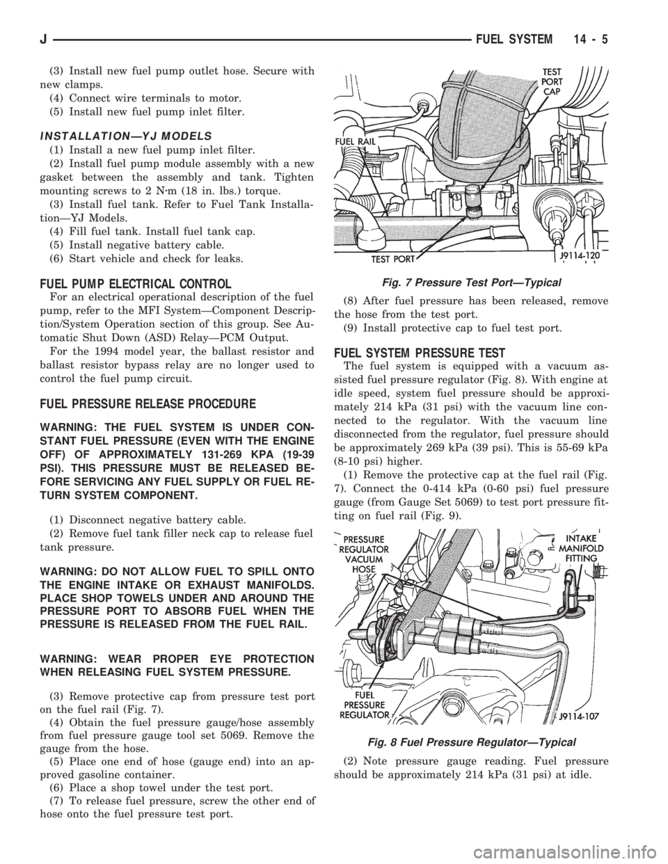
(3) Remove protective cap from pressure test port
on the fuel rail (Fig. 7).
(4) Obtain the fuel pressure gauge/hose assembly
from fuel pressure gauge tool set 5069. Remove the
gauge from the hose.
(5) Place one end of hose (gauge end) into an ap-
proved gasoline container.
(6) Place a shop towel under the test port.
(7) To release fuel pressure, screw the other end of
hose onto the fuel pressure test port.(8) After fuel pressure has been released, remove
the hose from the test port.
(9) Install protective cap to fuel test port.
FUEL SYSTEM PRESSURE TEST
The fuel system is equipped with a vacuum as-
sisted fuel pressure regulator (Fig. 8). With engine at
idle speed, system fuel pressure should be approxi-
mately 214 kPa (31 psi) with the vacuum line con-
nected to the regulator. With the vacuum line
disconnected from the regulator, fuel pressure should
be approximately 269 kPa (39 psi). This is 55-69 kPa
(8-10 psi) higher.
(1) Remove the protective cap at the fuel rail (Fig.
7). Connect the 0-414 kPa (0-60 psi) fuel pressure
gauge (from Gauge Set 5069) to test port pressure fit-
ting on fuel rail (Fig. 9).
(2) Note pressure gauge reading. Fuel pressure
should be approximately 214 kPa (31 psi) at idle.
Fig. 7 Pressure Test PortÐTypical
Fig. 8 Fuel Pressure RegulatorÐTypical
JFUEL SYSTEM 14 - 5
Page 978 of 1784
MULTI-PORT FUEL INJECTION (MFI)ÐCOMPONENT DESCRIPTION/SYSTEM
OPERATION
INDEX
page page
Air Conditioning (A/C) Clutch RelayÐPCM Output.24
Air Conditioning (A/C) ControlsÐPCM Input.... 19
Auto Shut Down (ASD) RelayÐPCM Output.... 24
Automatic Shut Down (ASD) SenseÐPCM Input . 19
Battery VoltageÐPCM Input................ 19
Brake SwitchÐPCM Input.................. 20
Camshaft Position SensorÐPCM Input........ 20
Crankshaft Position SensorÐPCM Input....... 20
Data Link ConnectorÐPCM Input............ 20
Data Link ConnectorÐPCM Output........... 24
EMR LampÐPCM Output.................. 24
Engine Coolant Temperature SensorÐPCM Input . 21
Extended Idle SwitchÐPCM Input............ 21
Fuel InjectorsÐPCM Output................ 25
Fuel Pressure Regulator................... 30
Fuel Pump RelayÐPCM Output............. 25
Fuel Rail............................... 30
General Information....................... 17
Generator FieldÐPCM Output............... 25
Generator LampÐPCM Output.............. 25
Idle Air Control (IAC) MotorÐPCM Output...... 25
Ignition Circuit SenseÐPCM Input............ 21
Ignition CoilÐPCM Output.................. 26Intake Air Temperature SensorÐPCM Input.... 20
Malfunction Indicator LampÐPCM Output...... 26
Manifold Absolute Pressure (MAP) SensorÐ
PCM Input............................ 21
Open Loop/Closed Loop Modes of Operation . . . 27
Overdrive/Override Switch.................. 22
Oxygen (O2S) SensorÐPCM Input........... 22
Park/Neutral SwitchÐPCM Input............. 22
Power Ground........................... 22
Power Steering Pressure SwitchÐPCM Input . . . 22
Powertrain Control Module (PCM)............ 18
Radiator Fan RelayÐPCM Output............ 26
SCI ReceiveÐPCM Input.................. 22
SCI TransmitÐPCM Output................. 26
Sensor ReturnÐPCM Input................. 23
Shift IndicatorÐPCM Output................ 26
Speed ControlÐPCM Input................. 23
Speed ControlÐPCM Output................ 27
TachometerÐPCM Output.................. 27
Throttle Body............................ 29
Throttle Position Sensor (TPS)ÐPCM Input..... 23
Torque Converter Clutch RelayÐPCM Output . . . 27
Vehicle Speed SensorÐPCM Input........... 23
GENERAL INFORMATION
All 2.5L 4 cylinder and 4.0L 6 cylinder engines are
equipped with sequential Multi-Port Fuel Injection
(MFI). The MFI system provides precise air/fuel ra-
tios for all driving conditions.
The Powertrain Control Module (PCM) operates
the fuel system. The PCM was formerly referred to
as the SBEC or engine controller. The PCM is a pre-
programmed, dual microprocessor digital computer.
It regulates ignition timing, air-fuel ratio, emission
control devices, charging system, speed control, air
conditioning compressor clutch engagement and idle
speed. The PCM can adapt its programming to meet
changing operating conditions.
Powertrain Control Module (PCM) Inputsrep-
resent the instantaneous engine operating conditions.
Air-fuel mixture and ignition timing calibrations for
various driving and atmospheric conditions are pre-
programmed into the PCM. The PCM monitors and
analyzes various inputs. It then computes engine fuel
and ignition timing requirements based on these in-
puts. Fuel delivery control and ignition timing will
then be adjusted accordingly.
Other inputs to the PCM are provided by the brake
light switch, air conditioning select switch and the
speed control switches. All inputs to the PCM are
converted into signals.
Electrically operated fuel injectors spray fuel in
precise metered amounts into the intake port directlyabove the intake valve. The injectors are fired in a
specific sequence by the PCM. The PCM maintains
an air/fuel ratio of 14.7 to 1 by constantly adjusting
injector pulse width. Injector pulse width is the
length of time that the injector opens and sprays fuel
into the chamber. The PCM adjusts injector pulse
width by opening and closing the ground path to the
injector.
Manifold absolute pressure (air density) and engine
rpm (speed) are the primary inputs that determine
fuel injector pulse width. The PCM also monitors
other inputs when adjusting air-fuel ratio.
Inputs That Effect Fuel Injector Pulse Width
²Exhaust gas oxygen content
²Engine coolant temperature
²Manifold absolute pressure (MAP)
²Engine speed
²Throttle position
²Battery voltage
²Air conditioning selection
²Transmission gear selection (automatic transmis-
sions only)
²Speed control
The powertrain control module (PCM) adjusts igni-
tion timing by controlling ignition coil operation. The
ignition coil receives battery voltage when the igni-
tion key is in the run or starter position. The PCM
provides a ground for the ignition coil. The coil dis-
JFUEL SYSTEM 14 - 17
Page 980 of 1784
²Signal ground
Powertrain Control Module (PCM) Outputs
²A/C clutch relay
²Idle air control (IAC) motor
²Auto shut down (ASD) relay
²Generator field
²Malfunction indicator lamp
²Fuel injectors
²Fuel pump relay
²Ignition coil
²SCI transmit (DRB scan tool connection)
²Shift indicator lamp (manual transmission only)
²Speed control vacuum solenoid
²Speed control vent solenoid
²Tachometer (on instrument panel, if equipped)
²Torque converter clutch relay (3-speed auto. trans.
only)
The PCM contains a voltage convertor. This con-
verts battery voltage to a regulated 8.0 volts. It is
used to power the crankshaft position sensor and
camshaft position sensor. The PCM also provides a
five (5) volt supply for the Manifold Absolute Pres-
sure (MAP) sensor and Throttle Position Sensor
(TPS).
AIR CONDITIONING (A/C) CONTROLSÐPCM INPUT
The A/C control system information applies to fac-
tory installed air conditioning units only.
A/C SELECT SIGNAL:When the A/C switch is
in the ON position and the A/C low pressure switch
is closed, an input signal is sent to the powertrain
control module (PCM). The signal informs the PCM
that the A/C has been selected. The PCM adjusts idle
speed to a pre-programmed rpm through the idle air
control (IAC) motor to compensate for increased en-
gine load.
A/C REQUEST SIGNAL:Once A/C has been se-
lected, the PCM receives the A/C request signal from
the evaporator switch. The input indicates that the
evaporator temperature is in the proper range for
A/C application. The PCM uses this input to cycle
the A/C compressor clutch (through the A/C relay). It
will also determine the correct engine idle speed
through the IAC motor position.
If the A/C low pressure switch opens (indicating a
low refrigerant level), the PCM will not receive an
A/C select signal. The PCM will then remove the
ground from the A/C relay. This will deactivate the
A/C compressor clutch.
If the evaporator switch opens, (indicating that
evaporator is not in proper temperature range), the
PCM will not receive the A/C request signal. The
PCM will then remove the ground from the A/C re-
lay, deactivating the A/C compressor clutch.
AUTOMATIC SHUT DOWN (ASD) SENSEÐPCM
INPUT
A 12 volt signal at this input indicates to the PCM
that the ASD has been activated. The ASD relay is
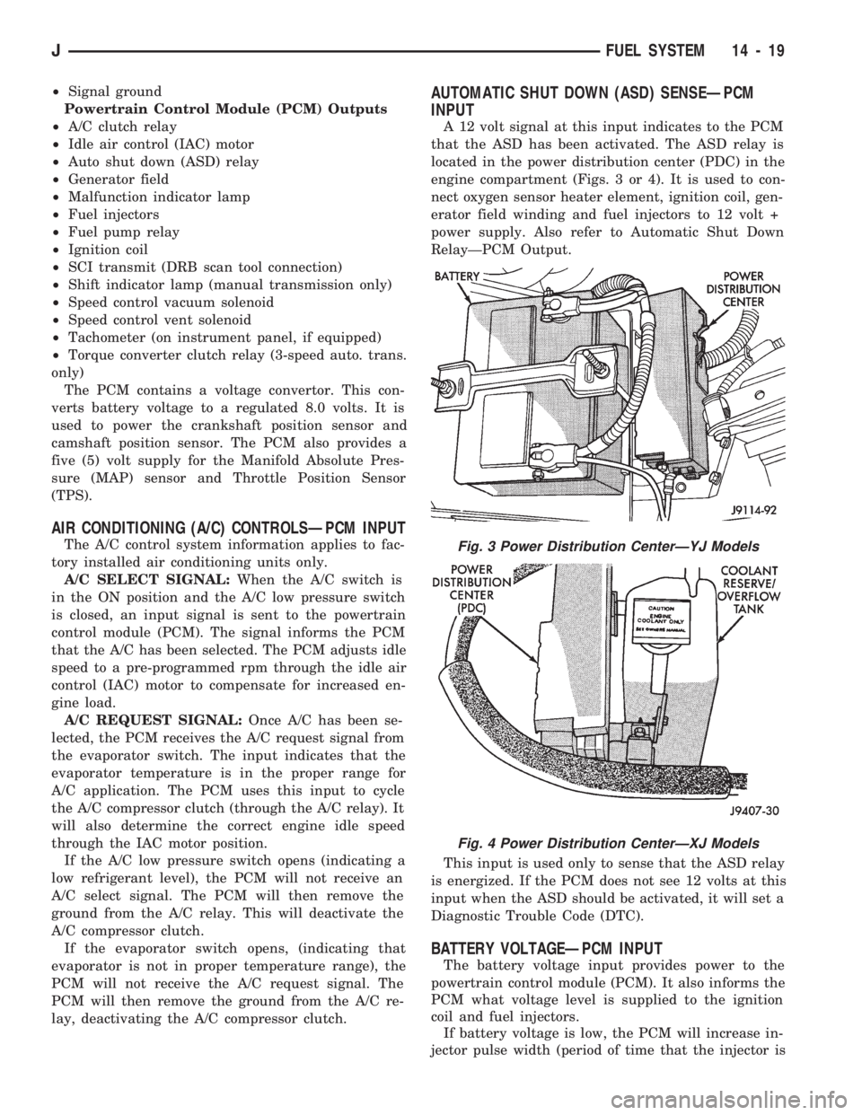
located in the power distribution center (PDC) in the
engine compartment (Figs. 3 or 4). It is used to con-
nect oxygen sensor heater element, ignition coil, gen-
erator field winding and fuel injectors to 12 volt +
power supply. Also refer to Automatic Shut Down
RelayÐPCM Output.
This input is used only to sense that the ASD relay
is energized. If the PCM does not see 12 volts at this
input when the ASD should be activated, it will set a
Diagnostic Trouble Code (DTC).
BATTERY VOLTAGEÐPCM INPUT
The battery voltage input provides power to the
powertrain control module (PCM). It also informs the
PCM what voltage level is supplied to the ignition
coil and fuel injectors.
If battery voltage is low, the PCM will increase in-
jector pulse width (period of time that the injector is
Fig. 3 Power Distribution CenterÐYJ Models
Fig. 4 Power Distribution CenterÐXJ Models
JFUEL SYSTEM 14 - 19
Page 985 of 1784
AIR CONDITIONING (A/C) CLUTCH RELAYÐPCM
OUTPUT
The powertrain control module (PCM) activates the
A/C compressor through the A/C clutch relay. The
PCM regulates A/C compressor operation by switch-
ing the ground circuit for the A/C clutch relay on
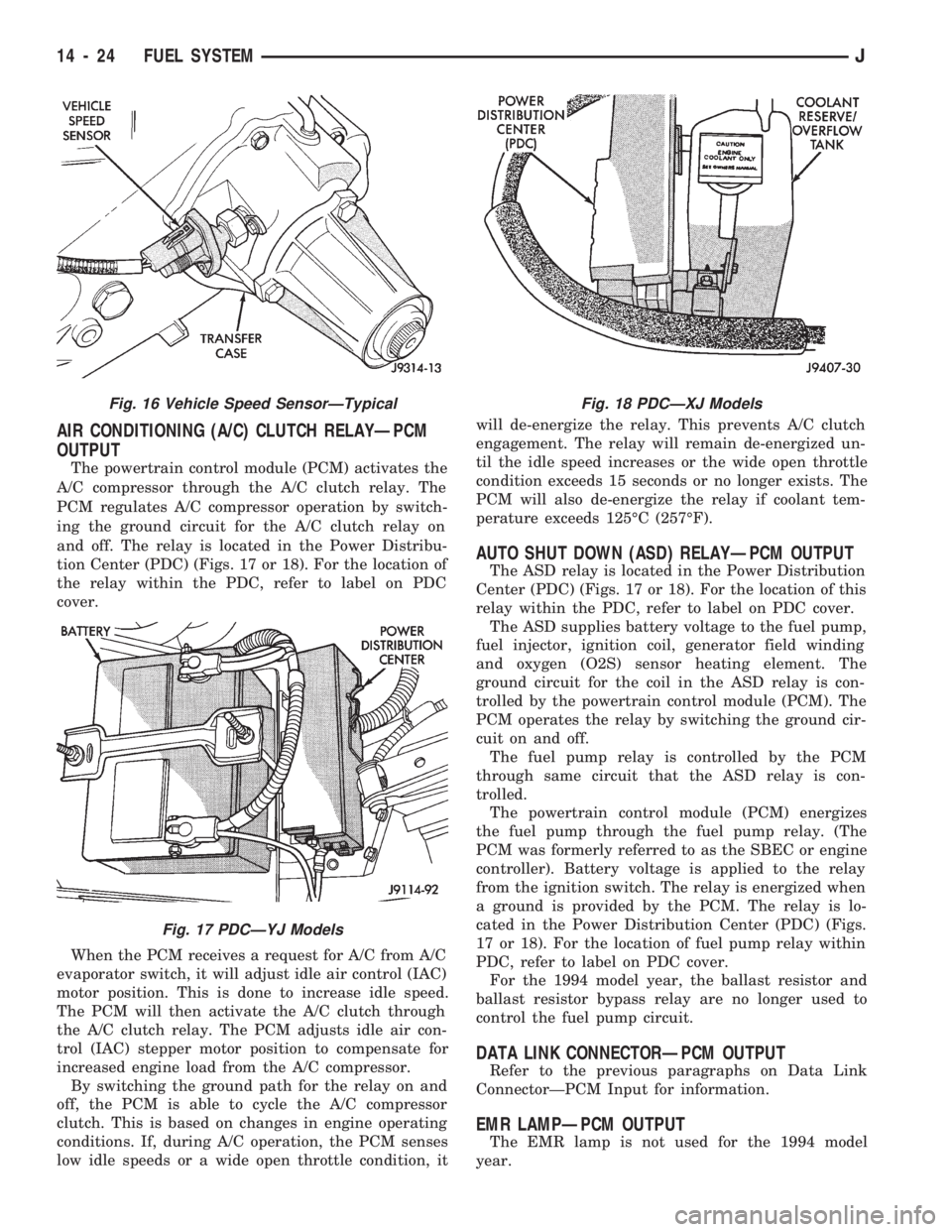
and off. The relay is located in the Power Distribu-
tion Center (PDC) (Figs. 17 or 18). For the location of
the relay within the PDC, refer to label on PDC
cover.
When the PCM receives a request for A/C from A/C
evaporator switch, it will adjust idle air control (IAC)
motor position. This is done to increase idle speed.
The PCM will then activate the A/C clutch through
the A/C clutch relay. The PCM adjusts idle air con-
trol (IAC) stepper motor position to compensate for
increased engine load from the A/C compressor.
By switching the ground path for the relay on and
off, the PCM is able to cycle the A/C compressor
clutch. This is based on changes in engine operating
conditions. If, during A/C operation, the PCM senses
low idle speeds or a wide open throttle condition, itwill de-energize the relay. This prevents A/C clutch
engagement. The relay will remain de-energized un-
til the idle speed increases or the wide open throttle
condition exceeds 15 seconds or no longer exists. The
PCM will also de-energize the relay if coolant tem-
perature exceeds 125ÉC (257ÉF).
AUTO SHUT DOWN (ASD) RELAYÐPCM OUTPUT
The ASD relay is located in the Power Distribution
Center (PDC) (Figs. 17 or 18). For the location of this
relay within the PDC, refer to label on PDC cover.
The ASD supplies battery voltage to the fuel pump,
fuel injector, ignition coil, generator field winding
and oxygen (O2S) sensor heating element. The
ground circuit for the coil in the ASD relay is con-
trolled by the powertrain control module (PCM). The
PCM operates the relay by switching the ground cir-
cuit on and off.
The fuel pump relay is controlled by the PCM
through same circuit that the ASD relay is con-
trolled.
The powertrain control module (PCM) energizes
the fuel pump through the fuel pump relay. (The
PCM was formerly referred to as the SBEC or engine
controller). Battery voltage is applied to the relay
from the ignition switch. The relay is energized when
a ground is provided by the PCM. The relay is lo-
cated in the Power Distribution Center (PDC) (Figs.
17 or 18). For the location of fuel pump relay within
PDC, refer to label on PDC cover.
For the 1994 model year, the ballast resistor and
ballast resistor bypass relay are no longer used to
control the fuel pump circuit.
DATA LINK CONNECTORÐPCM OUTPUT
Refer to the previous paragraphs on Data Link
ConnectorÐPCM Input for information.
EMR LAMPÐPCM OUTPUT
The EMR lamp is not used for the 1994 model
year.
Fig. 16 Vehicle Speed SensorÐTypical
Fig. 17 PDCÐYJ Models
Fig. 18 PDCÐXJ Models
14 - 24 FUEL SYSTEMJ
Page 986 of 1784
FUEL PUMP RELAYÐPCM OUTPUT
The PCM energizes the fuel pump through the fuel
pump relay. Battery voltage is applied to the relay
from the ignition switch. The relay is energized when
a ground is provided by the PCM. Refer to Automatic
Shut Down Relay for additional information.
FUEL INJECTORSÐPCM OUTPUT
Six individual fuel injectors are used with the 4.0L
6 cylinder engine. Four individual fuel injectors are
used with the 2.5L 4 cylinder engine. The injectors
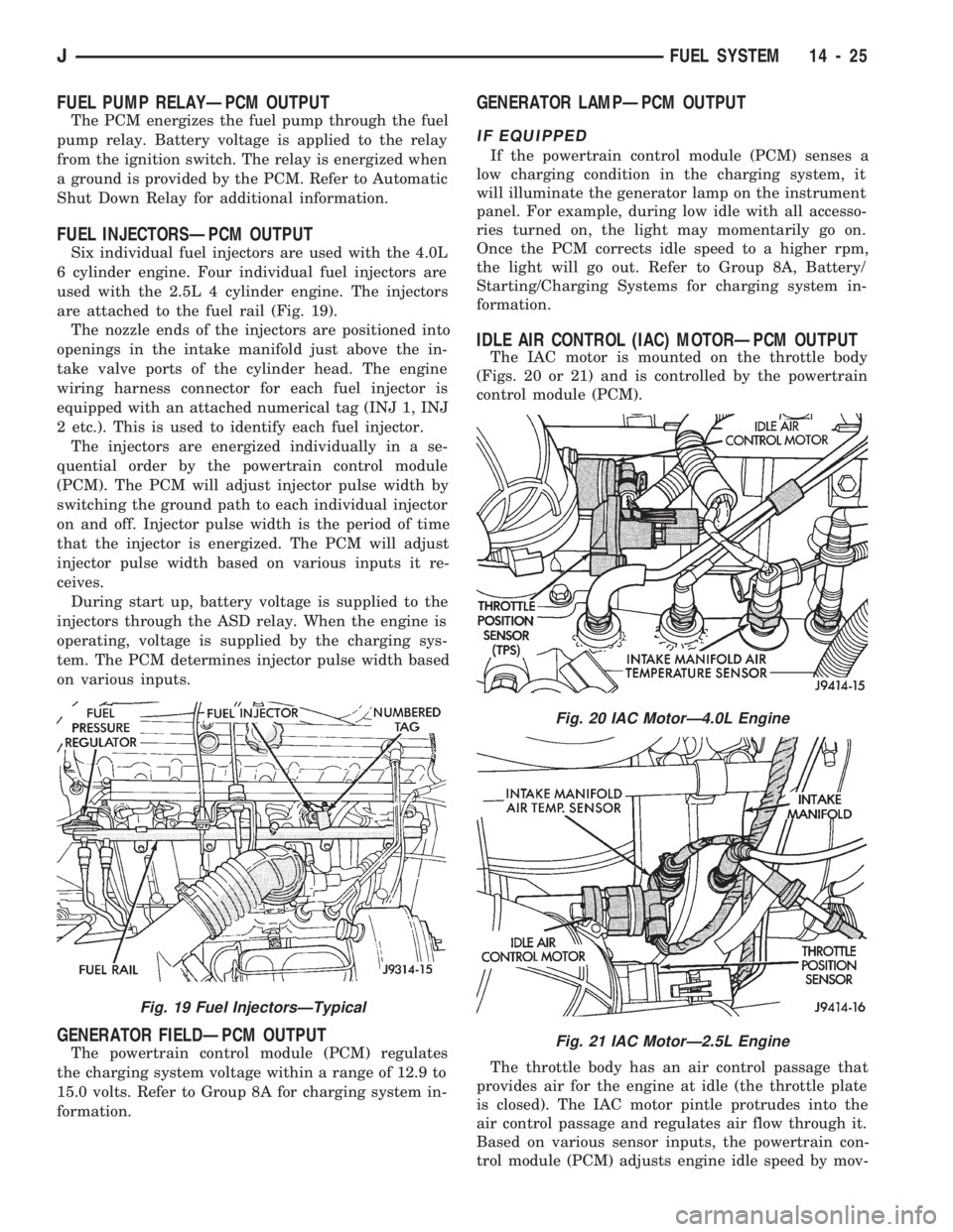
are attached to the fuel rail (Fig. 19).
The nozzle ends of the injectors are positioned into
openings in the intake manifold just above the in-
take valve ports of the cylinder head. The engine
wiring harness connector for each fuel injector is
equipped with an attached numerical tag (INJ 1, INJ
2 etc.). This is used to identify each fuel injector.
The injectors are energized individually in a se-
quential order by the powertrain control module
(PCM). The PCM will adjust injector pulse width by
switching the ground path to each individual injector
on and off. Injector pulse width is the period of time
that the injector is energized. The PCM will adjust
injector pulse width based on various inputs it re-
ceives.
During start up, battery voltage is supplied to the
injectors through the ASD relay. When the engine is
operating, voltage is supplied by the charging sys-
tem. The PCM determines injector pulse width based
on various inputs.
GENERATOR FIELDÐPCM OUTPUT
The powertrain control module (PCM) regulates
the charging system voltage within a range of 12.9 to
15.0 volts. Refer to Group 8A for charging system in-
formation.
GENERATOR LAMPÐPCM OUTPUT
IF EQUIPPED
If the powertrain control module (PCM) senses a
low charging condition in the charging system, it
will illuminate the generator lamp on the instrument
panel. For example, during low idle with all accesso-
ries turned on, the light may momentarily go on.
Once the PCM corrects idle speed to a higher rpm,
the light will go out. Refer to Group 8A, Battery/
Starting/Charging Systems for charging system in-
formation.
IDLE AIR CONTROL (IAC) MOTORÐPCM OUTPUT
The IAC motor is mounted on the throttle body
(Figs. 20 or 21) and is controlled by the powertrain
control module (PCM).
The throttle body has an air control passage that
provides air for the engine at idle (the throttle plate
is closed). The IAC motor pintle protrudes into the
air control passage and regulates air flow through it.
Based on various sensor inputs, the powertrain con-
trol module (PCM) adjusts engine idle speed by mov-
Fig. 19 Fuel InjectorsÐTypical
Fig. 20 IAC MotorÐ4.0L Engine
Fig. 21 IAC MotorÐ2.5L Engine
JFUEL SYSTEM 14 - 25
Page 987 of 1784
ing the IAC motor pintle in and out of the air control
passage. The IAC motor is positioned when the igni-
tion key is turned to the On position.
A (factory adjusted) set screw is used to mechani-
cally limit the position of the throttle body throttle
plate.Never attempt to adjust the engine idle
speed using this screw.All idle speed functions are
controlled by the PCM.
IGNITION COILÐPCM OUTPUT
System voltage is supplied to the ignition coil pos-
itive terminal. The powertrain control module (PCM)
operates the ignition coil.Base (initial) ignition
timing is not adjustable.The PCM adjusts ignition
timing to meet changing engine operating conditions.
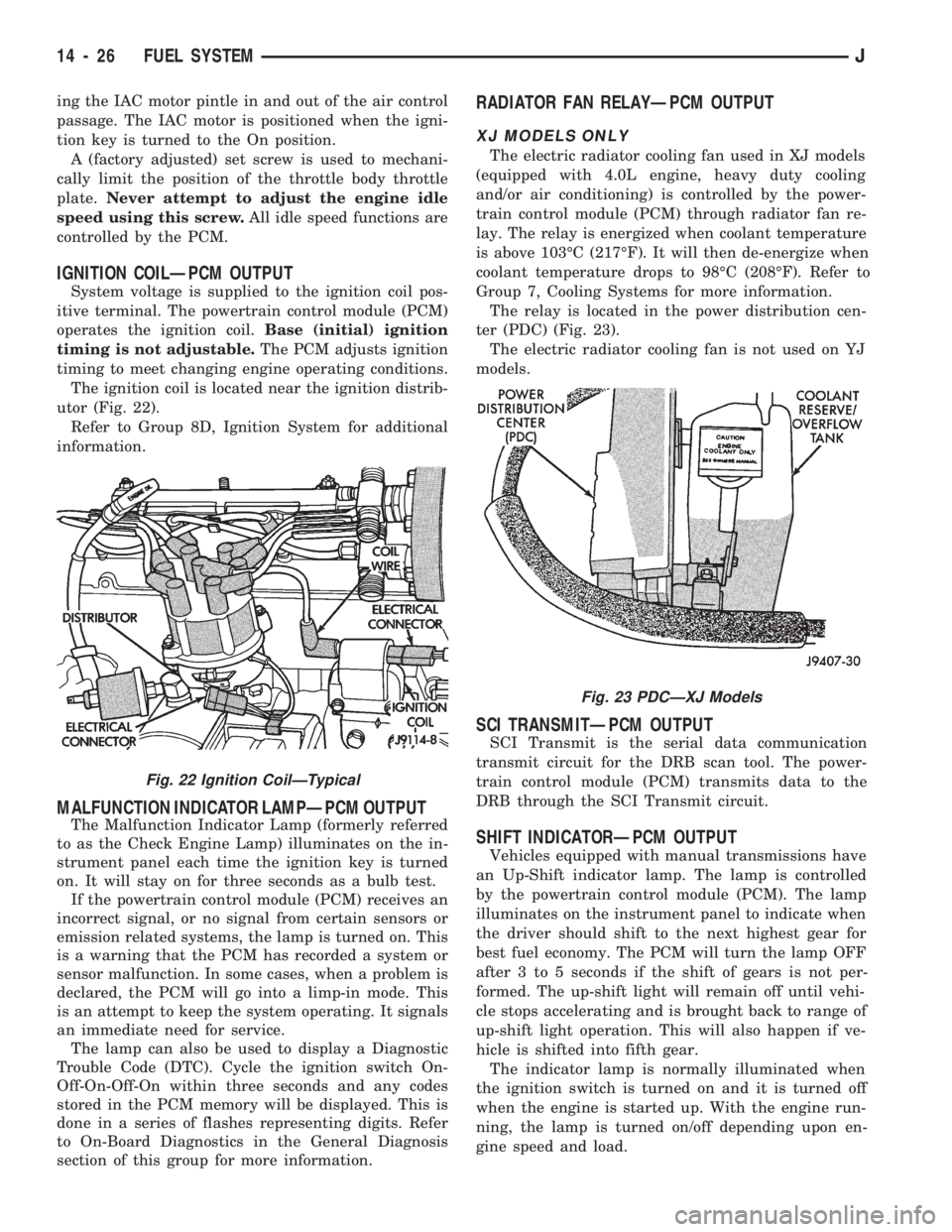
The ignition coil is located near the ignition distrib-
utor (Fig. 22).
Refer to Group 8D, Ignition System for additional
information.
MALFUNCTION INDICATOR LAMPÐPCM OUTPUT
The Malfunction Indicator Lamp (formerly referred
to as the Check Engine Lamp) illuminates on the in-
strument panel each time the ignition key is turned
on. It will stay on for three seconds as a bulb test.
If the powertrain control module (PCM) receives an
incorrect signal, or no signal from certain sensors or
emission related systems, the lamp is turned on. This
is a warning that the PCM has recorded a system or
sensor malfunction. In some cases, when a problem is
declared, the PCM will go into a limp-in mode. This
is an attempt to keep the system operating. It signals
an immediate need for service.
The lamp can also be used to display a Diagnostic
Trouble Code (DTC). Cycle the ignition switch On-
Off-On-Off-On within three seconds and any codes
stored in the PCM memory will be displayed. This is
done in a series of flashes representing digits. Refer
to On-Board Diagnostics in the General Diagnosis
section of this group for more information.
RADIATOR FAN RELAYÐPCM OUTPUT
XJ MODELS ONLY
The electric radiator cooling fan used in XJ models
(equipped with 4.0L engine, heavy duty cooling
and/or air conditioning) is controlled by the power-
train control module (PCM) through radiator fan re-
lay. The relay is energized when coolant temperature
is above 103ÉC (217ÉF). It will then de-energize when
coolant temperature drops to 98ÉC (208ÉF). Refer to
Group 7, Cooling Systems for more information.
The relay is located in the power distribution cen-
ter (PDC) (Fig. 23).
The electric radiator cooling fan is not used on YJ
models.
SCI TRANSMITÐPCM OUTPUT
SCI Transmit is the serial data communication
transmit circuit for the DRB scan tool. The power-
train control module (PCM) transmits data to the
DRB through the SCI Transmit circuit.
SHIFT INDICATORÐPCM OUTPUT
Vehicles equipped with manual transmissions have
an Up-Shift indicator lamp. The lamp is controlled
by the powertrain control module (PCM). The lamp
illuminates on the instrument panel to indicate when
the driver should shift to the next highest gear for
best fuel economy. The PCM will turn the lamp OFF
after 3 to 5 seconds if the shift of gears is not per-
formed. The up-shift light will remain off until vehi-
cle stops accelerating and is brought back to range of
up-shift light operation. This will also happen if ve-
hicle is shifted into fifth gear.
The indicator lamp is normally illuminated when
the ignition switch is turned on and it is turned off
when the engine is started up. With the engine run-
ning, the lamp is turned on/off depending upon en-
gine speed and load.
Fig. 23 PDCÐXJ Models
Fig. 22 Ignition CoilÐTypical
14 - 26 FUEL SYSTEMJ