1994 JEEP CHEROKEE window
[x] Cancel search: windowPage 765 of 1784
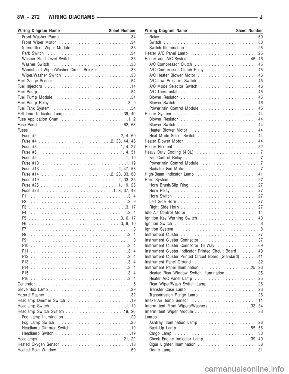
Wiring Diagram Name Sheet Number
Front Washer Pump.........................34
Front Wiper Motor..........................34
Intermittent Wiper Module.....................33
Park Switch..............................34
Washer Fluid Level Switch.....................33
Washer Switch............................33
Windshield Wiper/Washer Circuit Breaker...........33
Wiper/Washer Switch........................33
Fuel Gauge Sensor...........................54
Fuel Injectors...............................14
Fuel Pump.................................54
Fuel Pump Module...........................54
Fuel Pump Relay............................3,9
Fuel Tank System............................54
Full Time Indicator Lamp.....................39, 40
Fuse Application Chart........................1,2
Fuse Panel..............................62, 63
Fuses
Fuse #2.............................2,4,60
Fuse #4..........................2,33,44,46
Fuse #5.............................1,4,27
Fuse #6.............................1,4,51
Fuse #9...............................1,19
Fuse #10..............................1,19
Fuse #13............................2,47,58
Fuse #14.........................2,23,33,60
Fuse #19............................2,33,35
Fuse #25............................1,19,25
Fuse #26..........................1,8,37,43
F1 ...................................3,4
F2 ...................................3,9
F3 ...................................3,17
F4 ...................................3,4
F5 .................................3,6,17
F6 .................................3,9,10
F7 .....................................3
F8 ...................................3,4
F9 .....................................3
F10 ...................................3,4
F11 ...................................3,4
F12 ...................................3,4
F13 ...................................3,4
F14 ...................................3,4
F15 ...................................3,4
F16 ...................................3,4
Generator..................................5
Glove Box Lamp.............................29
Hazard Flasher..............................32
Headlamp Dimmer Switch.......................19
Headlamp Switch...........................1,19
Headlamp Switch System.....................19, 20
Fog Lamp Illumination........................20
Fog Lamp Switch...........................20
Headlamp Dimmer Switch.....................19
Headlamp Switch...........................19
Headlamps..............................21, 22
Heated Oxygen Sensor.........................13
Heated Rear Window..........................60Wiring Diagram Name Sheet Number
Relay...................................60
Switch..................................60
Switch Illumination..........................25
Heater A/C Panel Lamp........................25
Heater and A/C System......................45, 46
A/C Compressor Clutch.......................45
A/C Compressor Clutch Relay...................45
A/C Heater Blower Motor......................46
A/C Low Pressure Switch.....................45
A/C Mode Selector Switch.....................46
A/C Thermostat............................45
Blower Resistor............................46
Blower Switch.............................46
Powertrain Control Module.....................45
Heater System..............................44
Blower Resistor............................44
Blower Switch.............................44
Heater Blower Motor.........................44
Heat Mode Select Switch......................44
Heater Blower Motor..........................44
Heater Element..............................52
Heavy Duty Cooling (4.0L).......................7
Fan Control Relay...........................7
Powertrain Control Module.....................7
Radiator Fan Motor..........................7
High-Beam Indicator Lamp......................41
Horn System...............................27
Horn Brush/Slip Ring........................27
Horn Relay...............................27
Horn Switch..............................27
Left Side Horn.............................27
Right Side Horn............................27
Idle Air Control Motor.........................14
Ignition Key Warning Switch.....................43
Ignition Switch...............................8
Ignition System..............................8
Instrument Cluster............................37
Instrument Cluster Connector.....................37
Instrument Cluster Connector 16 Way...............69
Instrument Cluster Indicator Printed Circuit Board.......40
Instrument Cluster Printed Circuit Board (Standard)......41
Instrument Panel Ground.......................32
Instrument Panel Illumination..................25, 26
Heated Rear Window Switch Illumination...........25
Heater A/C Panel Lamp.......................25
Rear Wiper/Wash Switch Lamp..................26
Transfer Case Lamp.........................26
Transmission Range Lamp.....................26
Intake Air Temp Sensor........................11
Intermittent Front Wipers/Washers...............33, 34
Intermittent Wiper Module.......................33
Lamps
Ashtray Illumination Lamp.....................26
Back-Up Lamp..........................55, 56
Cargo Lamp..............................30
Check Engine Indicator Lamp................39, 40
Cigar Lighter Illumination......................58
Dome Lamp..............................31
8W - 272 WIRING DIAGRAMSJ
Page 766 of 1784
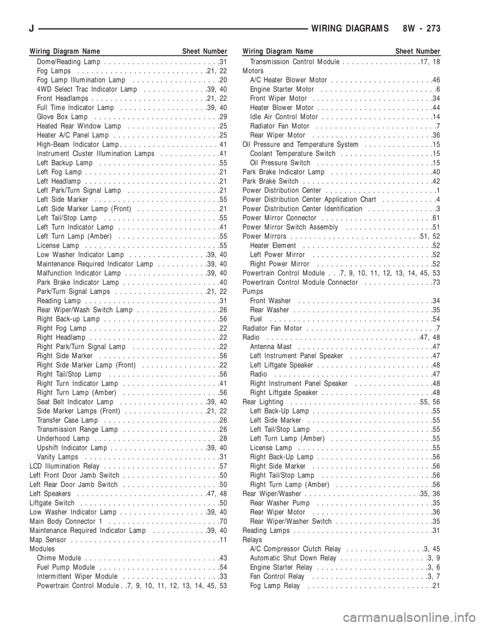
Wiring Diagram Name Sheet Number
Dome/Reading Lamp.........................31
Fog Lamps............................21, 22
Fog Lamp Illumination Lamp...................20
4WD Select Trac Indicator Lamp..............39, 40
Front Headlamps.........................21, 22
Full Time Indicator Lamp...................39, 40
Glove Box Lamp...........................29
Heated Rear Window Lamp....................25
Heater A/C Panel Lamp.......................25
High-Beam Indicator Lamp.....................41
Instrument Cluster Illumination Lamps.............41
Left Backup Lamp..........................55
Left Fog Lamp.............................21
Left Headlamp.............................21
Left Park/Turn Signal Lamp....................21
Left Side Marker...........................55
Left Side Marker Lamp (Front)..................21
Left Tail/Stop Lamp.........................55
Left Turn Indicator Lamp......................41
Left Turn Lamp (Amber)......................55
License Lamp.............................55
Low Washer Indicator Lamp.................39, 40
Maintenance Required Indicator Lamp...........39, 40
Malfunction Indicator Lamp..................39, 40
Park Brake Indicator Lamp.....................40
Park/Turn Signal Lamps....................21, 22
Reading Lamp.............................31
Rear Wiper/Wash Switch Lamp..................26
Right Back-up Lamp.........................56
Right Fog Lamp............................22
Right Headlamp............................22
Right Park/Turn Signal Lamp...................22
Right Side Marker..........................56
Right Side Marker Lamp (Front).................22
Right Tail/Stop Lamp........................56
Right Turn Indicator Lamp.....................41
Right Turn Lamp (Amber).....................56
Seat Belt Indicator Lamp...................39, 40
Side Marker Lamps (Front)..................21, 22
Transfer Case Lamp.........................26
Transmission Range Lamp.....................26
Underhood Lamp...........................28
Upshift Indicator Lamp.....................39, 40
Vanity Lamps.............................31
LCD Illumination Relay.........................57
Left Front Door Jamb Switch.....................50
Left Rear Door Jamb Switch.....................50
Left Speakers............................47, 48
Liftgate Switch..............................50
Low Washer Indicator Lamp...................39, 40
Main Body Connector 1........................70
Maintenance Required Indicator Lamp............39, 40
Map Sensor................................11
Modules
Chime Module.............................43
Fuel Pump Module..........................54
Intermittent Wiper Module.....................33
Powertrain Control Module . .7, 9, 10, 11, 12, 13, 14, 45, 53Wiring Diagram Name Sheet Number
Transmission Control Module.................17, 18
Motors
A/C Heater Blower Motor......................46
Engine Starter Motor.........................6
Front Wiper Motor..........................34
Heater Blower Motor.........................44
Idle Air Control Motor........................14
Radiator Fan Motor..........................7
Rear Wiper Motor..........................36
Oil Pressure and Temperature System...............15
Coolant Temperature Switch....................15
Oil Pressure Switch.........................15
Park Brake Indicator Lamp......................40
Park Brake Switch............................42
Power Distribution Center........................1
Power Distribution Center Application Chart............4
Power Distribution Center Identification...............3
Power Mirror Connector........................61
Power Mirror Switch Assembly...................51
Power Mirrors............................51, 52
Heater Element............................52
Left Power Mirror..........................52
Right Power Mirror.........................52
Powertrain Control Module . . .7, 9, 10, 11, 12, 13, 14, 45, 53
Powertrain Control Module Connector...............73
Pumps
Front Washer.............................34
Rear Washer..............................35
Fuel...................................54
Radiator Fan Motor............................7
Radio.................................47, 48
Antenna Mast.............................47
Left Instrument Panel Speaker..................47
Left Liftgate Speaker.........................48
Radio..................................47
Right Instrument Panel Speaker.................48
Right Liftgate Speaker........................48
Rear Lighting............................55, 56
Left Back-Up Lamp..........................55
Left Side Marker...........................55
Left Tail/Stop Lamp.........................55
Left Turn Lamp (Amber)......................55
License Lamp.............................55
Right Back-Up Lamp.........................56
Right Side Marker..........................56
Right Tail/Stop Lamp........................56
Right Turn Lamp (Amber).....................56
Rear Wiper/Washer.........................35, 36
Rear Washer Pump.........................35
Rear Wiper Motor..........................36
Rear Wiper/Washer Switch.....................35
Reading Lamps..............................31
Relays
A/C Compressor Clutch Relay.................3,45
Automatic Shut Down Relay...................3,9
Engine Starter Relay........................3,6
Fan Control Relay.........................3,7
Fog Lamp Relay...........................21
JWIRING DIAGRAMS 8W - 273
Page 767 of 1784
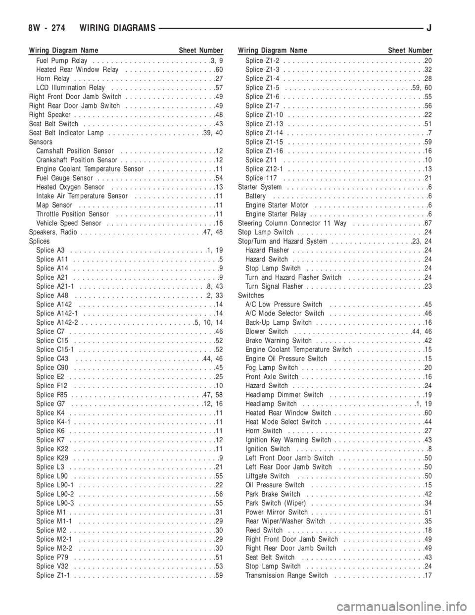
Wiring Diagram Name Sheet Number
Fuel Pump Relay..........................3,9
Heated Rear Window Relay....................60
Horn Relay...............................27
LCD Illumination Relay.......................57
Right Front Door Jamb Switch....................49
Right Rear Door Jamb Switch....................49
Right Speaker...............................48
Seat Belt Switch.............................43
Seat Belt Indicator Lamp.....................39, 40
Sensors
Camshaft Position Sensor.....................12
Crankshaft Position Sensor.....................12
Engine Coolant Temperature Sensor...............11
Fuel Gauge Sensor..........................54
Heated Oxygen Sensor.......................13
Intake Air Temperature Sensor..................11
Map Sensor..............................11
Throttle Position Sensor......................11
Vehicle Speed Sensor........................16
Speakers, Radio...........................47, 48
Splices
Splice A3..............................1,19
Splice A11................................5
Splice A14................................9
Splice A21................................9
Splice A21-1............................8,43
Splice A48.............................2,33
Splice A142..............................14
Splice A142-1.............................14
Splice A142-2.........................5,10,14
Splice C7................................46
Splice C15...............................52
Splice C15-1..............................52
Splice C43............................44, 46
Splice C90...............................45
Splice E2................................25
Splice F12...............................10
Splice F85.............................47, 58
Splice G7.............................12, 16
Splice K4................................11
Splice K4-1...............................11
Splice K6................................11
Splice K7................................12
Splice K22...............................11
Splice K29................................9
Splice L3................................21
Splice L90...............................55
Splice L90-1..............................22
Splice L90-2..............................56
Splice L90-3..............................55
Splice M1................................31
Splice M1-1..............................29
Splice M2................................30
Splice M2-1..............................29
Splice M2-2..............................30
Splice P79...............................51
Splice V32...............................53
Splice Z1-1...............................59Wiring Diagram Name Sheet Number
Splice Z1-2...............................20
Splice Z1-3...............................32
Splice Z1-4...............................28
Splice Z1-5............................59, 60
Splice Z1-6...............................55
Splice Z1-7...............................56
Splice Z1-10..............................22
Splice Z1-13..............................51
Splice Z1-14...............................7
Splice Z1-15..............................59
Splice Z1-16..............................16
Splice Z11...............................10
Splice Z12-1..............................13
Splice 117...............................21
Starter System...............................6
Battery..................................6
Engine Starter Motor.........................6
Engine Starter Relay..........................6
Steering Column Connector 11 Way................67
Stop Lamp Switch............................24
Stop/Turn and Hazard System..................23, 24
Hazard Flasher.............................24
Hazard Switch.............................24
Stop Lamp Switch..........................24
Turn and Hazard Flasher Switch.................24
Turn Signal Flasher..........................23
Switches
A/C Low Pressure Switch.....................45
A/C Mode Selector Switch.....................46
Back-Up Lamp Switch........................16
Blower Switch..........................44, 46
Brake Warning Switch........................42
Engine Coolant Temperature Switch...............15
Engine Oil Pressure Switch....................15
Fog Lamp Switch...........................20
Front Axle Switch...........................16
Hazard Switch.............................24
Headlamp Dimmer Switch.....................19
Headlamp Switch.........................1,19
Heated Rear Window Switch....................60
Heat Mode Select Switch......................44
Horn Switch..............................27
Ignition Key Warning Switch....................43
Ignition Switch.............................8
Left Front Door Jamb Switch...................50
Left Rear Door Jamb Switch...................50
Liftgate Switch............................50
Oil Pressure Switch.........................15
Park Brake Switch..........................42
Park Switch (Wiper).........................34
Power Mirror Switch.........................51
Rear Wiper/Washer Switch.....................35
Reed Switch..............................18
Right Front Door Jamb Switch..................49
Right Rear Door Jamb Switch..................49
Seat Belt Switch...........................43
Stop Lamp Switch..........................24
Transmission Range Switch....................17
8W - 274 WIRING DIAGRAMSJ
Page 878 of 1784

SIDE CLEARANCE MEASUREMENT
Slide snug-fitting feeler gauge between the con-
necting rod and crankshaft journal flange. Refer to
Engine Specifications for the proper clearance. Re-
place the connecting rod if the side clearance is not
within specification.
PISTON FITTING
MICROMETER METHOD
(1) Measure the inside diameter of the cylinder
bore at a point 58.725 mm (2-5/16 inches) below top
of bore.
(2) Measure outside diameter of the piston. Be-
cause pistons are cam ground, measure at right an-
gle to piston pin at center line of pin (Fig. 8).
The difference between cylinder bore diameter and
piston diameter is piston-to-bore clearance.
FEELER GAUGE METHOD
(1) Remove the rings from the piston.
(2) Insert a long 0.025 mm (0.001 inch) feeler
gauge into the cylinder bore.
(3) Insert the piston, top first, into cylinder bore
alongside the feeler gauge. With entire piston in-
serted into cylinder bore, the piston should not bind
against feeler gauge.
(4) Repeat steps with a long 0.051 mm (0.002 inch)
feeler gauge. The piston should bind.
(5) If the piston binds on 0.025 mm (0.001 inch)
feeler gauge, the piston is too large or cylinder bore
is too small. If the piston does not bind on 0.051 mm
(0.002 inch) feeler gauge, the piston is too small for
cylinder bore. Pistons up to 0.102 mm (0.004 inch)undersize may be enlarged by knurling or shot-peen-
ing. Replace pistons that are 0.102 mm (0.004 inch)
or more undersize.
PISTON PIN
REMOVAL
Piston pins are press-fitted into the connecting rods
and require no locking device.
(1) Position the piston and connecting rod assem-
bly on an arbor press.
(2) Apply force to a piloted driver and press the
pin completely out of the connecting rod and piston
assembly (Fig. 9). Note position of the pin through
the gauge window of removal support tool.
INSPECTION
(1) Inspect the piston pin and pin bore in the con-
necting rod for nicks and burrs. Remove as neces-
sary. Never reuse a piston pin after it has been
installed in and removed from a connecting rod.
(2) With the pin removed from the piston and con-
necting rod, clean and dry piston pin bores and the
replacement piston pin.
(3) Position the piston so that the pin bore is in
vertical position. Insert the pin in bore. At room tem-
perature, the replacement pin should slide com-
pletely through the pin bore in piston by force of
gravity.
(4) Replace piston if pin jams in the pin bore.
INSTALLATION
(1) Insert the piston pin pilot through the piston
and connecting rod pin bores. Ensure that the arrow
on the piston crown is pointing up (Fig. 10).
Fig. 8 Piston Dimensions
Fig. 9 Piston Pin Removal/Installation
J2.5L ENGINE 9 - 37
Page 918 of 1784

The difference between cylinder bore diameter and
piston diameter is piston-to-bore clearance.
FEELER GAUGE METHOD
(1) Remove the rings from the piston.
(2) Insert a long 0.025 mm (0.001 inch) feeler
gauge into the cylinder bore.
(3) Insert the piston, top first, into cylinder bore
alongside the feeler gauge. With entire piston in-
serted into cylinder bore, the piston should not bind
against feeler gauge.
(4) Repeat steps with a long 0.051 mm (0.002 inch)
feeler gauge. The piston should bind.
(5) If the piston binds on 0.025 mm (0.001 inch)
feeler gauge, the piston is too large or cylinder bore
is too small. If the piston does not bind on 0.051 mm
(0.002 inch) feeler gauge, the piston is too small for
cylinder bore. Pistons up to 0.102 mm (0.004 inch)
undersize may be enlarged by knurling or shot-peen-
ing. Replace pistons that are 0.102 mm (0.004 inch)
or more undersize.
PISTON PIN
REMOVAL
Piston pins are press-fitted into the connecting rods
and require no locking device.
(1) Position the piston and connecting rod assem-
bly on an arbor press.
(2) Apply force to a piloted driver and press the
pin completely out of the connecting rod and piston
assembly (Fig. 9). Note position of the pin through
the gauge window of removal support tool.INSPECTION
(1) Inspect the piston pin and pin bore in the con-
necting rod for nicks and burrs. Remove as neces-
sary. Never reuse a piston pin after it has been
installed in and removed from a connecting rod.
(2) With the pin removed from the piston and con-
necting rod, clean and dry piston pin bores and the
replacement piston pin.
(3) Position the piston so that the pin bore is in
vertical position. Insert the pin in bore. At room tem-
perature, the replacement pin should slide com-
pletely through the pin bore in piston by force of
gravity.
(4) Replace piston if pin jams in the pin bore.
INSTALLATION
(1) Insert the piston pin pilot through the piston
and connecting rod pin bores. Ensure that the arrow
on the piston crown is pointing up (Fig. 10).
(2) Position the pin pilot, piston and connecting
rod on a support with the squirt hole of the connect-
ing rod to the left-hand side (Fig. 10).
(3) Insert piston pin through the upper piston pin
bore and into the connecting rod pin bore.
(4) Position the piloted driver inside the piston pin
(Fig. 9).
(5) Using an arbor press, press the piston pin
through the connecting rod and piston bores until pin
pilot indexes with mark on the support. The piston
pin requires a 8 900 N (2,000 pounds) press-fit. If lit-
tle effort is required to install piston pin in a con-
necting rod, or if the rod moves laterally on the pin,
the connecting rod must be replaced.
Fig. 8 Piston Dimensions
Fig. 9 Piston Pin Removal/Installation
J4.0L ENGINE 9 - 77
Page 951 of 1784

CONSTRUCTION
The frame is constructed of high-strength channel
steel siderails and crossmembers. The crossmembers
join the siderails and retain them in alignment in re-
lation to each other. This provides resistance to
frame twists and strains.
FRAME ALIGNMENT
INCORRECT ALIGNMENT
Incorrect frame alignment is usually a result of:
²collision impact, or
²the vehicle being operated with excessive loads, or
²loads not positioned in a properly distributed man-
ner on the vehicle.
A mis-aligned frame will affect front axle and/or
rear axle alignment. It can cause excessive wear and
mechanical failures in the powertrain. Window glass
cracks and door opening/closing problems. Vehicle
performance can also be impaired.
RE-ALIGNMENT
With collision damage, it is important that the ex-
istence of any frame alignment damage be deter-
mined. If necessary, the frame should be correctly re-
aligned. Refer to the reference dimensions listed on
frame alignment dimension chart (Fig. 4).
FRAME INSPECTION/MEASUREMENTS
INSPECTION
Before proceeding with measurements, inspect all
components for visible damage and other metal dam-
age. Also, inspect all connections for loose and miss-
ing hardware.
All damaged areas must be repaired and/or the
components replaced, as necessary.
MEASUREMENTS
Measure the frame for mis-alignment with the
body attached to the frame. Figure 4 provides the
alignment reference dimensions. The following infor-
mation applies to all measurements.
(1) Place the vehicle on a level surface.
(2) If the vehicle is loaded, ensure that the vehicle
weight plus the payload does not exceed the gross ve-
hicle weight rating. Also, ensure that the load is dis-
tributed in the vehicle as evenly as possible.
(3) Measure the tire inflation pressures and adjust
the pressure, if necessary.
HORIZONTAL OR DIAGONAL FRAME MEASUREMENTS
Determine the frame horizontal non-square devia-
tion(s) according to the following procedure.
(1) Select several reference points along one frame
siderail, preferably at the crossmember junctions.(2) Transfer these reference points to the surface/
floor with a plumb bob. Paper sheets can be attached
to the surface below the reference points for better
measurement accuracy.
(3) Locate the reference points on the other frame
siderail and transfer them to the surface/floor with
the same procedure as above.
(4) Move the vehicle away and measure between
all the reference points diagonally from and parallel
to the siderails (Fig. 5). The measurements should
not differ by more than 6 mm (1/4 in).
(5) Measure the distance between the two front
reference points and the distance between the two
rear reference points. Divide each distance in half
and indicate the two half-way points on the surface/
floor. Designate the front point as ``1'' and the rear
point as ``2'' (Fig. 5).
(6) Place a chalk-line between points 1 and 2 and
``snap'' the string.
(7) Determine how close the center line is to the
diagonal intersection points A, B, C, D, E, and F in
Figure 5.
(8) The reference marks on the surface/floor will
provide an illustrated indication of the degree of
frame misalignment.
(9) A reference point transferred from one frame
siderail may be 3 mm (1/8 in) ahead or behind the
reference point from the opposite siderail.
(10) Frame bow to the side should not exceed 3
mm per 2,540 mm (1/8 inch per 100 inches) in
length.
(11) The overall width of the frame should not
vary more than 3 mm (1/8 in) from reference point-
to-reference point.
(12) Repeat steps (1) through (11) after straighten-
ing the frame to evaluate the effectiveness.
TWIST AND PARALLEL FRAME MEASUREMENTS
Determine the amount of frame twist and siderail
deviation according to the following procedure.
(1) Mark the vertical measurement reference
points under the frame siderails at 305-mm (12-in)
intervals starting at the rear frame crossmember.
(2) Measure the vertical distance up from a level
surface to each reference point located under the left
and right frame siderails.
(3) The distance to a reference point under one
frame siderail should be 3 mm (1/8 in) greater or less
than the point under the opposite siderail.
(4) Plot the measured vertical distances to scale on
a sheet of graph paper. Plot the distances so that the
frame siderails are located adjacent to each other.
Join the vertical distance points.
13 - 10 FRAME AND BUMPERSJ
Page 1456 of 1784
BODY COMPONENTSÐXJ VEHICLES
CONTENTS
page page
DOORS............................... 34
EXTERIOR COMPONENTS................. 3
FIXED WINDOW GLASS................. 73GENERAL BODY SERVICE INFORMATION.... 1
INTERIOR COMPONENTS................ 91
UNDERBODY COMPONENTS.............. 84
GENERAL BODY SERVICE INFORMATION
RIGHT HAND DRIVE VEHICLES
The XJ Body Components procedures in this sec-
tion were developed on a left hand drive (LHD) vehi-
cle. Unless a component is unique to a right hand
drive vehicle, it will not be specifically covered in
this section, i.e. cargo barrier. In general, compo-
nents on left hand drive vehicles will be located on
the opposite side in right hand drive vehicles.
LABELS/DECALS/PLATES
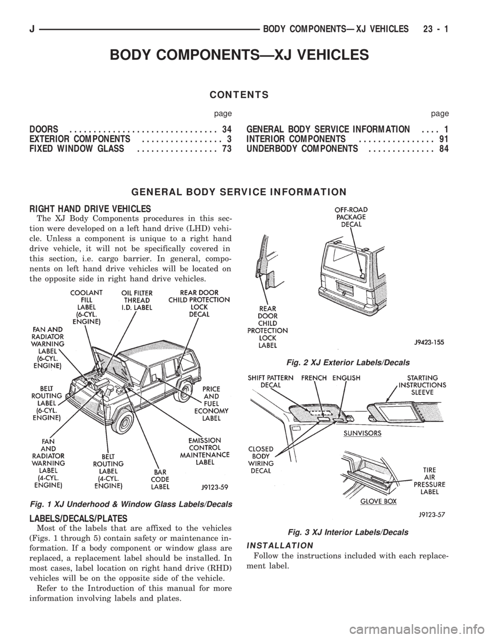
Most of the labels that are affixed to the vehicles
(Figs. 1 through 5) contain safety or maintenance in-
formation. If a body component or window glass are
replaced, a replacement label should be installed. In
most cases, label location on right hand drive (RHD)
vehicles will be on the opposite side of the vehicle.
Refer to the Introduction of this manual for more
information involving labels and plates.
INSTALLATION
Follow the instructions included with each replace-
ment label.
Fig. 1 XJ Underhood & Window Glass Labels/Decals
Fig. 2 XJ Exterior Labels/Decals
Fig. 3 XJ Interior Labels/Decals
JBODY COMPONENTSÐXJ VEHICLES 23 - 1
Page 1484 of 1784
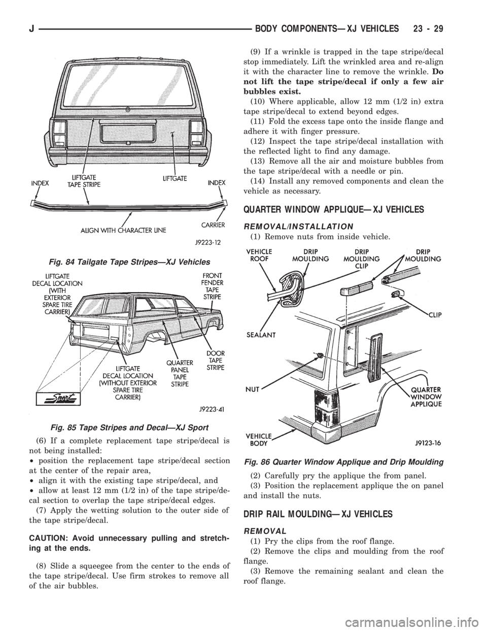
(6) If a complete replacement tape stripe/decal is
not being installed:
²position the replacement tape stripe/decal section
at the center of the repair area,
²align it with the existing tape stripe/decal, and
²allow at least 12 mm (1/2 in) of the tape stripe/de-
cal section to overlap the tape stripe/decal edges.
(7) Apply the wetting solution to the outer side of
the tape stripe/decal.
CAUTION: Avoid unnecessary pulling and stretch-
ing at the ends.
(8) Slide a squeegee from the center to the ends of
the tape stripe/decal. Use firm strokes to remove all
of the air bubbles.(9) If a wrinkle is trapped in the tape stripe/decal
stop immediately. Lift the wrinkled area and re-align
it with the character line to remove the wrinkle.Do
not lift the tape stripe/decal if only a few air
bubbles exist.
(10) Where applicable, allow 12 mm (1/2 in) extra
tape stripe/decal to extend beyond edges.
(11) Fold the excess tape onto the inside flange and
adhere it with finger pressure.
(12) Inspect the tape stripe/decal installation with
the reflected light to find any damage.
(13) Remove all the air and moisture bubbles from
the tape stripe/decal with a needle or pin.
(14) Install any removed components and clean the
vehicle as necessary.
QUARTER WINDOW APPLIQUEÐXJ VEHICLES
REMOVAL/INSTALLATION
(1) Remove nuts from inside vehicle.
(2) Carefully pry the applique the from panel.
(3) Position the replacement applique the on panel
and install the nuts.
DRIP RAIL MOULDINGÐXJ VEHICLES
REMOVAL
(1) Pry the clips from the roof flange.
(2) Remove the clips and moulding from the roof
flange.
(3) Remove the remaining sealant and clean the
roof flange.
Fig. 84 Tailgate Tape StripesÐXJ Vehicles
Fig. 85 Tape Stripes and DecalÐXJ Sport
Fig. 86 Quarter Window Applique and Drip Moulding
JBODY COMPONENTSÐXJ VEHICLES 23 - 29