1994 JEEP CHEROKEE window
[x] Cancel search: windowPage 1535 of 1784
(18) Install the rearview mirror on the bracket and
tighten the mirror setscrew to 2 Nzm (15 in-lbs) torque.
REAR QUARTER VENT WINDOW GLASSÐXJ
VEHICLES
REMOVAL
(1) Remove the vent window handle retaining pin
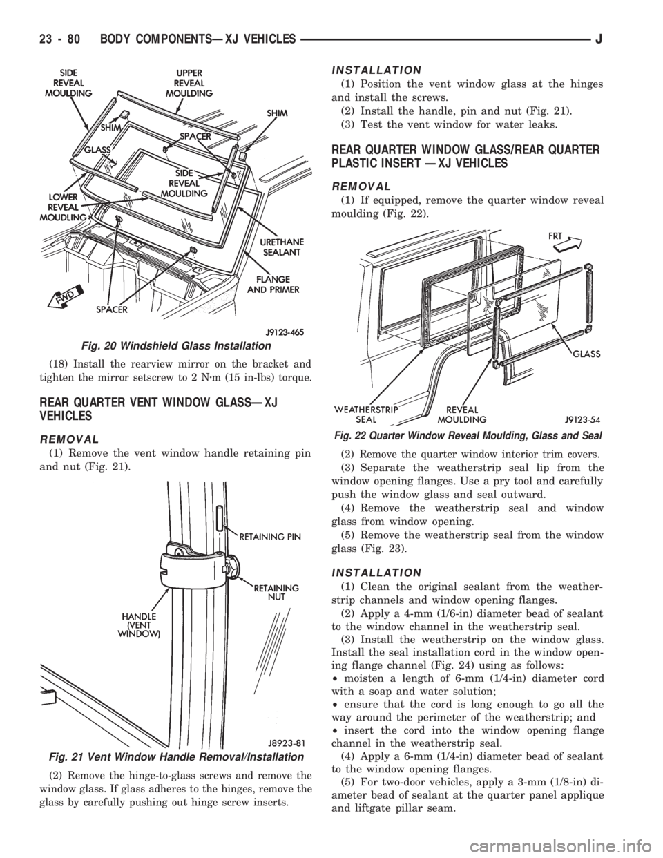
and nut (Fig. 21).
(2) Remove the hinge-to-glass screws and remove the
window glass. If glass adheres to the hinges, remove the
glass by carefully pushing out hinge screw inserts.
INSTALLATION
(1) Position the vent window glass at the hinges
and install the screws.
(2) Install the handle, pin and nut (Fig. 21).
(3) Test the vent window for water leaks.
REAR QUARTER WINDOW GLASS/REAR QUARTER
PLASTIC INSERT ÐXJ VEHICLES
REMOVAL
(1) If equipped, remove the quarter window reveal
moulding (Fig. 22).
(2) Remove the quarter window interior trim covers.
(3) Separate the weatherstrip seal lip from the
window opening flanges. Use a pry tool and carefully
push the window glass and seal outward.
(4) Remove the weatherstrip seal and window
glass from window opening.
(5) Remove the weatherstrip seal from the window
glass (Fig. 23).
INSTALLATION
(1) Clean the original sealant from the weather-
strip channels and window opening flanges.
(2) Apply a 4-mm (1/6-in) diameter bead of sealant
to the window channel in the weatherstrip seal.
(3) Install the weatherstrip on the window glass.
Install the seal installation cord in the window open-
ing flange channel (Fig. 24) using as follows:
²moisten a length of 6-mm (1/4-in) diameter cord
with a soap and water solution;
²ensure that the cord is long enough to go all the
way around the perimeter of the weatherstrip; and
²insert the cord into the window opening flange
channel in the weatherstrip seal.
(4) Apply a 6-mm (1/4-in) diameter bead of sealant
to the window opening flanges.
(5) For two-door vehicles, apply a 3-mm (1/8-in) di-
ameter bead of sealant at the quarter panel applique
and liftgate pillar seam.
Fig. 20 Windshield Glass Installation
Fig. 21 Vent Window Handle Removal/Installation
Fig. 22 Quarter Window Reveal Moulding, Glass and Seal
23 - 80 BODY COMPONENTSÐXJ VEHICLESJ
Page 1536 of 1784
(6) Position the quarter window glass and the weather-
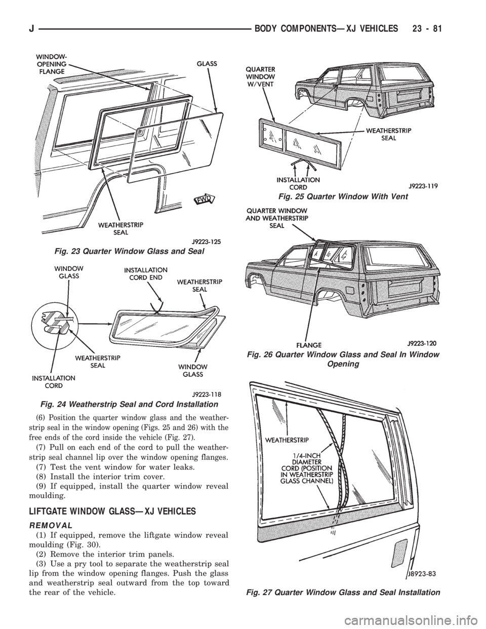
strip seal in the window opening (Figs. 25 and 26) with the
free ends of the cord inside the vehicle (Fig. 27).
(7) Pull on each end of the cord to pull the weather-
strip seal channel lip over the window opening flanges.
(7) Test the vent window for water leaks.
(8) Install the interior trim cover.
(9) If equipped, install the quarter window reveal
moulding.
LIFTGATE WINDOW GLASSÐXJ VEHICLES
REMOVAL
(1) If equipped, remove the liftgate window reveal
moulding (Fig. 30).
(2) Remove the interior trim panels.
(3) Use a pry tool to separate the weatherstrip seal
lip from the window opening flanges. Push the glass
and weatherstrip seal outward from the top toward
the rear of the vehicle.
Fig. 23 Quarter Window Glass and Seal
Fig. 25 Quarter Window With Vent
Fig. 26 Quarter Window Glass and Seal In Window
Opening
Fig. 27 Quarter Window Glass and Seal Installation
Fig. 24 Weatherstrip Seal and Cord Installation
JBODY COMPONENTSÐXJ VEHICLES 23 - 81
Page 1537 of 1784
(4) Remove the glass and weatherstrip seal from
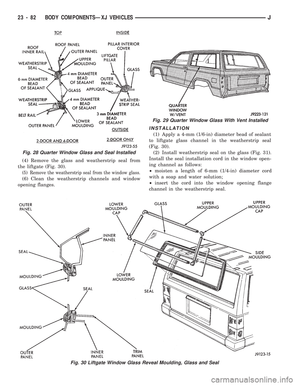
the liftgate (Fig. 30).
(5) Remove the weatherstrip seal from the window glass.
(6) Clean the weatherstrip channels and window
opening flanges.
INSTALLATION
(1) Apply a 4-mm (1/6-in) diameter bead of sealant
to liftgate glass channel in the weatherstrip seal
(Fig. 30).
(2) Install weatherstrip seal on the glass (Fig. 31).
Install the seal installation cord in the window open-
ing channel as follows:
²moisten a length of 6-mm (1/4-in) diameter cord
with a soap and water solution;
²insert the cord into the window opening flange
channel in the weatherstrip seal.
Fig. 29 Quarter Window Glass With Vent Installed
Fig. 30 Liftgate Window Glass Reveal Moulding, Glass and Seal
Fig. 28 Quarter Window Glass and Seal Installed
23 - 82 BODY COMPONENTSÐXJ VEHICLESJ
Page 1538 of 1784
(3) Apply a 6-mm (1/4-in) diameter bead of sealant
around the perimeter of the window opening flange
in the liftgate (Fig. 30).
(4) Install the window glass and the weatherstrip
seal in the window opening with the cord according
to the following instructions:
²position the window glass and the weatherstrip
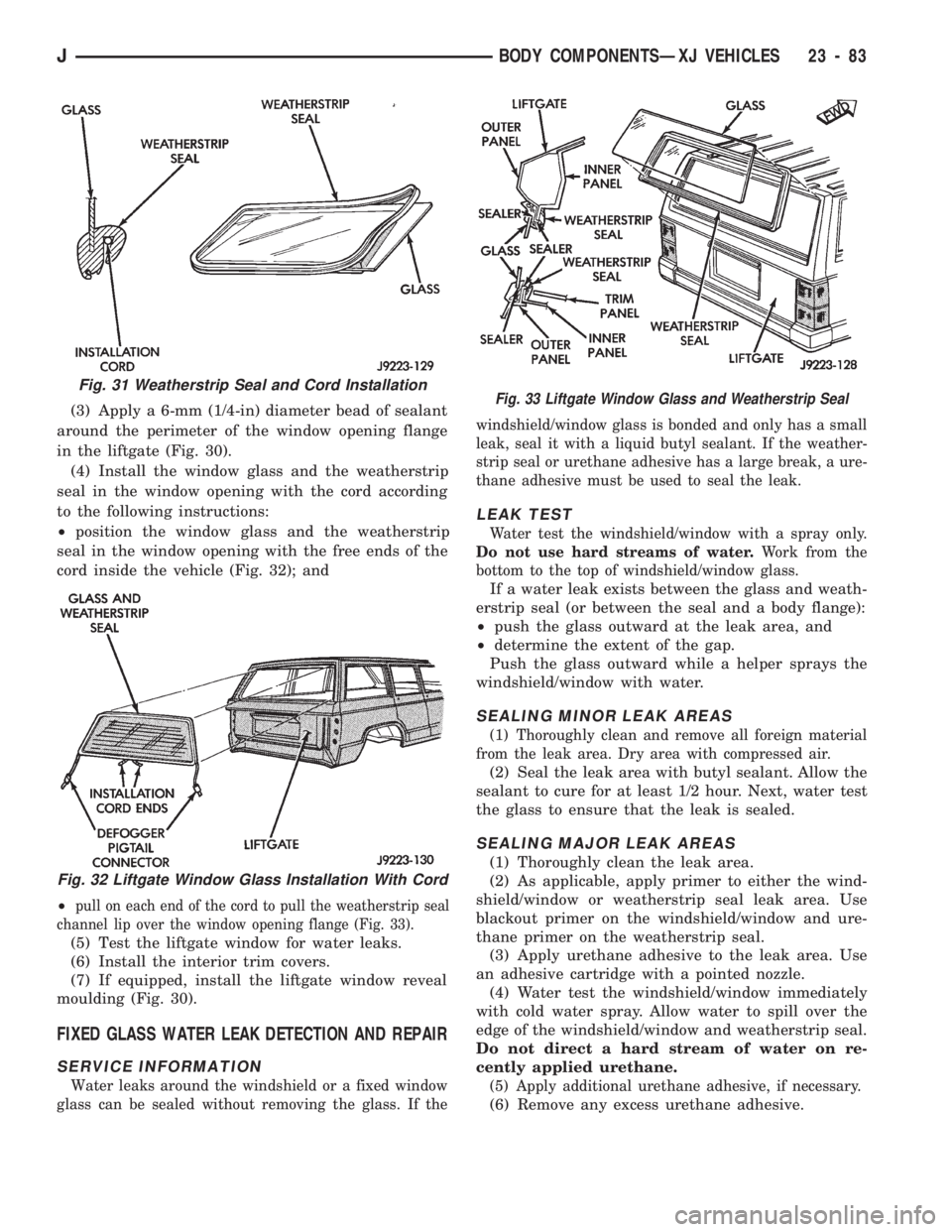
seal in the window opening with the free ends of the
cord inside the vehicle (Fig. 32); and
²
pull on each end of the cord to pull the weatherstrip seal
channel lip over the window opening flange (Fig. 33).
(5) Test the liftgate window for water leaks.
(6) Install the interior trim covers.
(7) If equipped, install the liftgate window reveal
moulding (Fig. 30).
FIXED GLASS WATER LEAK DETECTION AND REPAIR
SERVICE INFORMATION
Water leaks around the windshield or a fixed window
glass can be sealed without removing the glass. If thewindshield/window glass is bonded and only has a small
leak, seal it with a liquid butyl sealant. If the weather-
strip seal or urethane adhesive has a large break, a ure-
thane adhesive must be used to seal the leak.
LEAK TEST
Water test the windshield/window with a spray only.
Do not use hard streams of water.Work from the
bottom to the top of windshield/window glass.
If a water leak exists between the glass and weath-
erstrip seal (or between the seal and a body flange):
²push the glass outward at the leak area, and
²determine the extent of the gap.
Push the glass outward while a helper sprays the
windshield/window with water.
SEALING MINOR LEAK AREAS
(1) Thoroughly clean and remove all foreign material
from the leak area. Dry area with compressed air.
(2) Seal the leak area with butyl sealant. Allow the
sealant to cure for at least 1/2 hour. Next, water test
the glass to ensure that the leak is sealed.
SEALING MAJOR LEAK AREAS
(1) Thoroughly clean the leak area.
(2) As applicable, apply primer to either the wind-
shield/window or weatherstrip seal leak area. Use
blackout primer on the windshield/window and ure-
thane primer on the weatherstrip seal.
(3) Apply urethane adhesive to the leak area. Use
an adhesive cartridge with a pointed nozzle.
(4) Water test the windshield/window immediately
with cold water spray. Allow water to spill over the
edge of the windshield/window and weatherstrip seal.
Do not direct a hard stream of water on re-
cently applied urethane.
(5) Apply additional urethane adhesive, if necessary.
(6) Remove any excess urethane adhesive.
Fig. 31 Weatherstrip Seal and Cord Installation
Fig. 32 Liftgate Window Glass Installation With Cord
Fig. 33 Liftgate Window Glass and Weatherstrip Seal
JBODY COMPONENTSÐXJ VEHICLES 23 - 83
Page 1549 of 1784
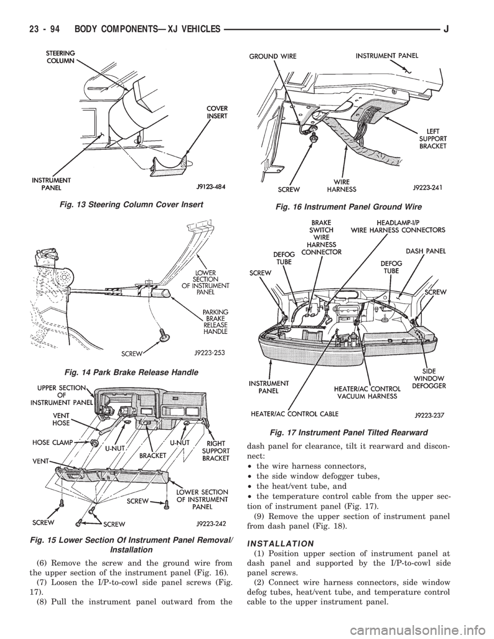
(6) Remove the screw and the ground wire from
the upper section of the instrument panel (Fig. 16).
(7) Loosen the I/P-to-cowl side panel screws (Fig.
17).
(8) Pull the instrument panel outward from thedash panel for clearance, tilt it rearward and discon-
nect:
²the wire harness connectors,
²the side window defogger tubes,
²the heat/vent tube, and
²the temperature control cable from the upper sec-
tion of instrument panel (Fig. 17).
(9) Remove the upper section of instrument panel
from dash panel (Fig. 18).
INSTALLATION
(1) Position upper section of instrument panel at
dash panel and supported by the I/P-to-cowl side
panel screws.
(2) Connect wire harness connectors, side window
defog tubes, heat/vent tube, and temperature control
cable to the upper instrument panel.
Fig. 13 Steering Column Cover Insert
Fig. 14 Park Brake Release Handle
Fig. 15 Lower Section Of Instrument Panel Removal/
Installation
Fig. 16 Instrument Panel Ground Wire
Fig. 17 Instrument Panel Tilted Rearward
23 - 94 BODY COMPONENTSÐXJ VEHICLESJ
Page 1551 of 1784
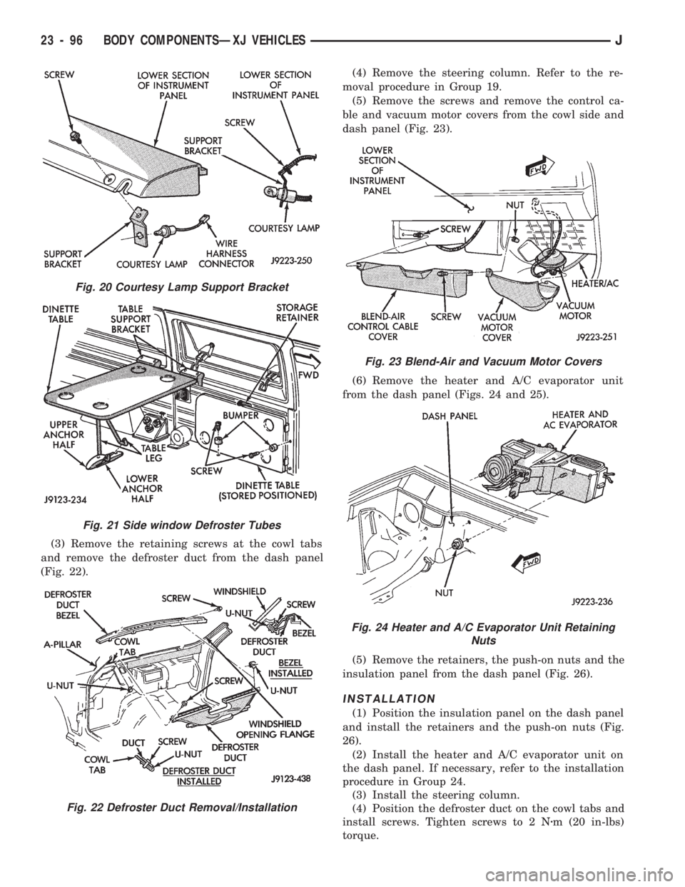
(3) Remove the retaining screws at the cowl tabs
and remove the defroster duct from the dash panel
(Fig. 22).(4) Remove the steering column. Refer to the re-
moval procedure in Group 19.
(5) Remove the screws and remove the control ca-
ble and vacuum motor covers from the cowl side and
dash panel (Fig. 23).
(6) Remove the heater and A/C evaporator unit
from the dash panel (Figs. 24 and 25).
(5) Remove the retainers, the push-on nuts and the
insulation panel from the dash panel (Fig. 26).
INSTALLATION
(1) Position the insulation panel on the dash panel
and install the retainers and the push-on nuts (Fig.
26).
(2) Install the heater and A/C evaporator unit on
the dash panel. If necessary, refer to the installation
procedure in Group 24.
(3) Install the steering column.
(4) Position the defroster duct on the cowl tabs and
install screws. Tighten screws to 2 Nzm (20 in-lbs)
torque.
Fig. 20 Courtesy Lamp Support Bracket
Fig. 21 Side window Defroster Tubes
Fig. 22 Defroster Duct Removal/Installation
Fig. 23 Blend-Air and Vacuum Motor Covers
Fig. 24 Heater and A/C Evaporator Unit Retaining
Nuts
23 - 96 BODY COMPONENTSÐXJ VEHICLESJ
Page 1587 of 1784
BODY COMPONENTSÐYJ VEHICLES
CONTENTS
page page
ADD-A-TRUNK........................ 198
DOORS.............................. 172
EXTERIOR COMPONENTS............... 134FIXED WINDOW GLASS................ 181
GENERAL SERVICE INFORMATION........ 132
INTERIOR COMPONENTS............... 188
GENERAL SERVICE INFORMATION
LABELS/DECALS/PLATES
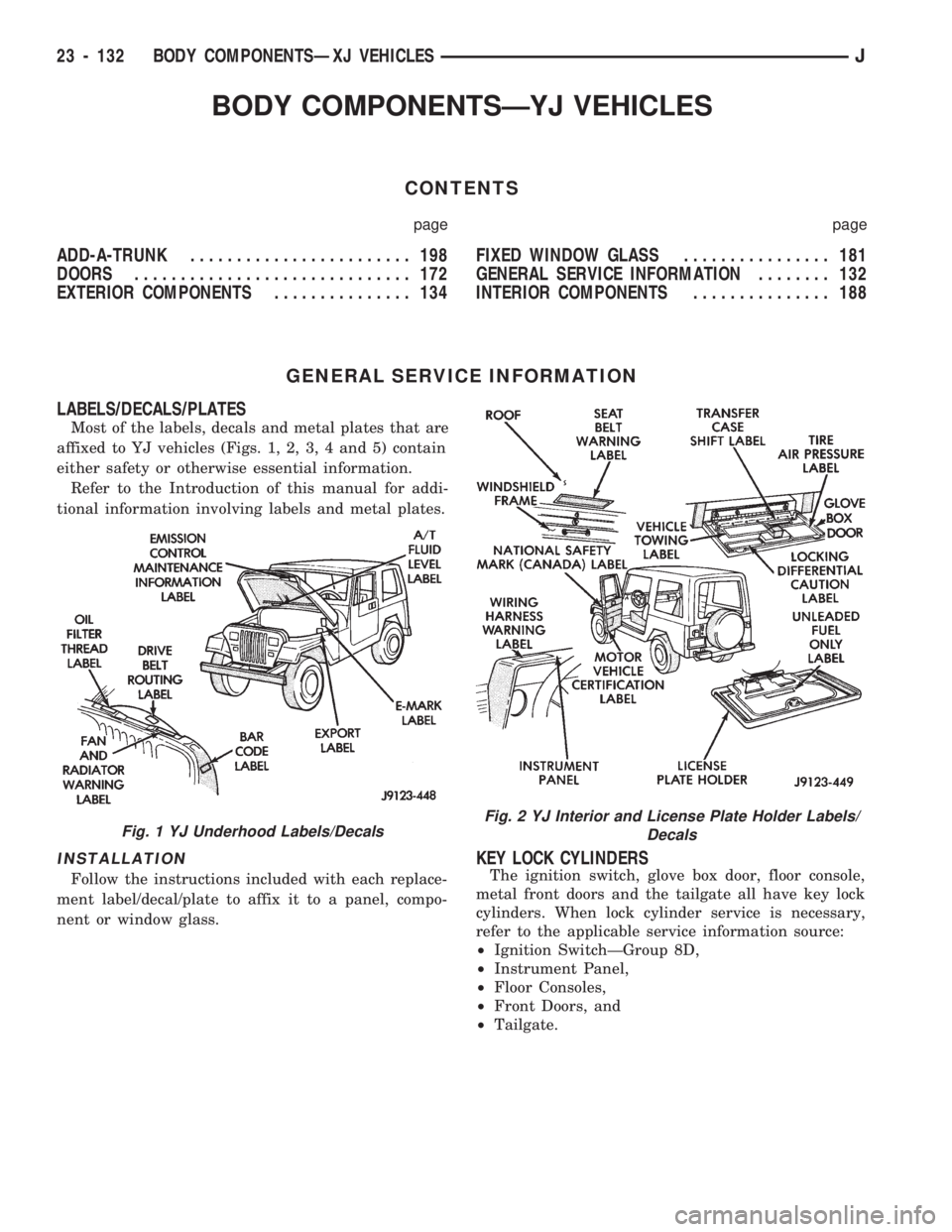
Most of the labels, decals and metal plates that are
affixed to YJ vehicles (Figs. 1, 2, 3, 4 and 5) contain
either safety or otherwise essential information.
Refer to the Introduction of this manual for addi-
tional information involving labels and metal plates.
INSTALLATION
Follow the instructions included with each replace-
ment label/decal/plate to affix it to a panel, compo-
nent or window glass.
KEY LOCK CYLINDERS
The ignition switch, glove box door, floor console,
metal front doors and the tailgate all have key lock
cylinders. When lock cylinder service is necessary,
refer to the applicable service information source:
²Ignition SwitchÐGroup 8D,
²Instrument Panel,
²Floor Consoles,
²Front Doors, and
²Tailgate.
Fig. 1 YJ Underhood Labels/DecalsFig. 2 YJ Interior and License Plate Holder Labels/
Decals
23 - 132 BODY COMPONENTSÐXJ VEHICLESJ
Page 1617 of 1784
INSTALLATION
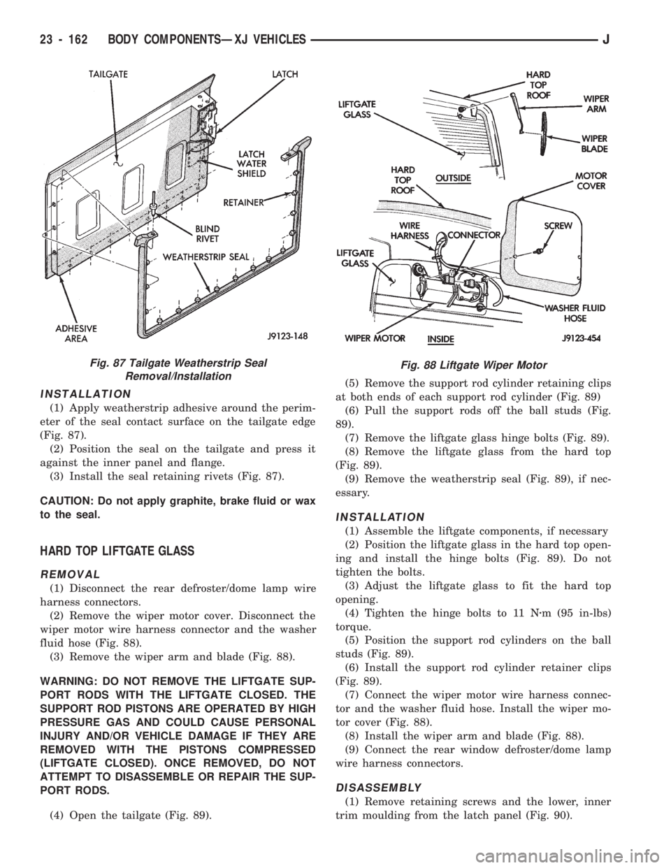
(1) Apply weatherstrip adhesive around the perim-
eter of the seal contact surface on the tailgate edge
(Fig. 87).
(2) Position the seal on the tailgate and press it
against the inner panel and flange.
(3) Install the seal retaining rivets (Fig. 87).
CAUTION: Do not apply graphite, brake fluid or wax
to the seal.
HARD TOP LIFTGATE GLASS
REMOVAL
(1) Disconnect the rear defroster/dome lamp wire
harness connectors.
(2) Remove the wiper motor cover. Disconnect the
wiper motor wire harness connector and the washer
fluid hose (Fig. 88).
(3) Remove the wiper arm and blade (Fig. 88).
WARNING: DO NOT REMOVE THE LIFTGATE SUP-
PORT RODS WITH THE LIFTGATE CLOSED. THE
SUPPORT ROD PISTONS ARE OPERATED BY HIGH
PRESSURE GAS AND COULD CAUSE PERSONAL
INJURY AND/OR VEHICLE DAMAGE IF THEY ARE
REMOVED WITH THE PISTONS COMPRESSED
(LIFTGATE CLOSED). ONCE REMOVED, DO NOT
ATTEMPT TO DISASSEMBLE OR REPAIR THE SUP-
PORT RODS.
(4) Open the tailgate (Fig. 89).(5) Remove the support rod cylinder retaining clips
at both ends of each support rod cylinder (Fig. 89)
(6) Pull the support rods off the ball studs (Fig.
89).
(7) Remove the liftgate glass hinge bolts (Fig. 89).
(8) Remove the liftgate glass from the hard top
(Fig. 89).
(9) Remove the weatherstrip seal (Fig. 89), if nec-
essary.
INSTALLATION
(1) Assemble the liftgate components, if necessary
(2) Position the liftgate glass in the hard top open-
ing and install the hinge bolts (Fig. 89). Do not
tighten the bolts.
(3) Adjust the liftgate glass to fit the hard top
opening.
(4) Tighten the hinge bolts to 11 Nzm (95 in-lbs)
torque.
(5) Position the support rod cylinders on the ball
studs (Fig. 89).
(6) Install the support rod cylinder retainer clips
(Fig. 89).
(7) Connect the wiper motor wire harness connec-
tor and the washer fluid hose. Install the wiper mo-
tor cover (Fig. 88).
(8) Install the wiper arm and blade (Fig. 88).
(9) Connect the rear window defroster/dome lamp
wire harness connectors.
DISASSEMBLY
(1) Remove retaining screws and the lower, inner
trim moulding from the latch panel (Fig. 90).
Fig. 87 Tailgate Weatherstrip Seal
Removal/InstallationFig. 88 Liftgate Wiper Motor
23 - 162 BODY COMPONENTSÐXJ VEHICLESJ