1994 JEEP CHEROKEE window
[x] Cancel search: windowPage 1621 of 1784
cloth. Use a plastic spreader to smooth-out the cloth
and resin. Use firm pressure to remove air bubbles
and to smooth-out the cloth.
(11) Allow the resin to ``cure''.
(12) Smooth-out the surface area to the contour of
the hard top with a 50-grit disc.
(13) Apply plastic filler to complete the repair.
Finish smoothing the surface area with 80-grit pa-
per.
(14) Repeat the previous step on the inside surface
area of the hard top.
(15) ``Featheredge'' the repaired surface area.
(16) Prime the repaired surface area with Ditzler
Epoxy Chromate Primer (DP-40/401), or an equiva-
lent product.
(17) Apply surface primer to the surface area.
(18) Sand the surface area for paint preparation.
After sanding, re-prime the surface area, if neces-
sary.
(19) Prime the surface area for the color coat.
(20) Color coat the repaired surface area.
FRACTURE REPAIR
(1) Use a grinder to remove the paint (from both,
the inner and outer surface areas of the hard top)
and to outline the damaged area.
(2) ``Stop-drill'' the crack(s) with a 3-mm (1/8-in)
diameter drill bit.(3) Bevel the edges of the crack(s) on both sides
with a rotary file.
The edges should be beveled on the inside and
outside of the top to ensure sufficient surface
area for good bonding.
(4) Complete the repairs with fiberglass cloth and
resin as described above in the hard top hole repair
procedure.
TEXTURED PAINT REPAIR
The textured paint applied to hard tops is available
from Mopar Parts sources. The paint supplied will
duplicate the original texture on the hard top.
SOFT TOP SERVICE INFORMATION
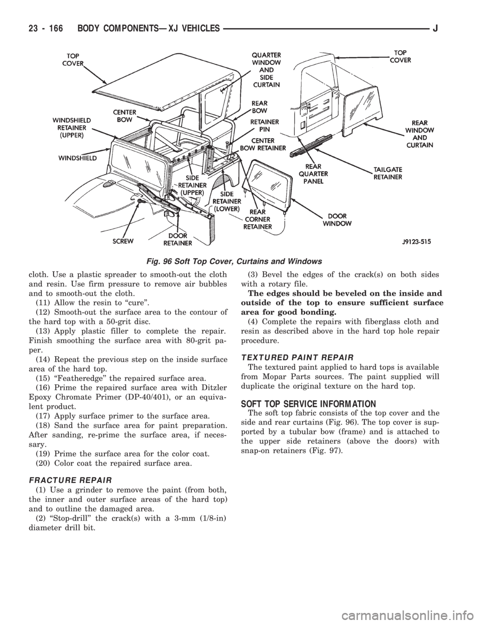
The soft top fabric consists of the top cover and the
side and rear curtains (Fig. 96). The top cover is sup-
ported by a tubular bow (frame) and is attached to
the upper side retainers (above the doors) with
snap-on retainers (Fig. 97).
Fig. 96 Soft Top Cover, Curtains and Windows
23 - 166 BODY COMPONENTSÐXJ VEHICLESJ
Page 1622 of 1784
SOFT TOP SERVICE
REMOVAL
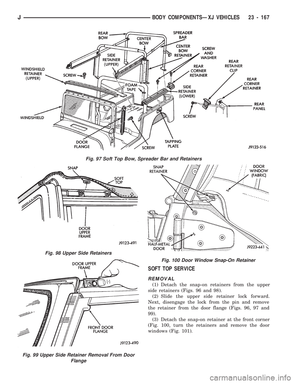
(1) Detach the snap-on retainers from the upper
side retainers (Figs. 96 and 98).
(2) Slide the upper side retainer lock forward.
Next, disengage the lock from the pin and remove
the retainer from the door flange (Figs. 96, 97 and
99).
(3) Detach the snap-on retainer at the front corner
(Fig. 100, turn the retainers and remove the door
windows (Fig. 101).
Fig. 97 Soft Top Bow, Spreader Bar and Retainers
Fig. 98 Upper Side Retainers
Fig. 99 Upper Side Retainer Removal From Door
Flange
Fig. 100 Door Window Snap-On Retainer
JBODY COMPONENTSÐXJ VEHICLES 23 - 167
Page 1623 of 1784
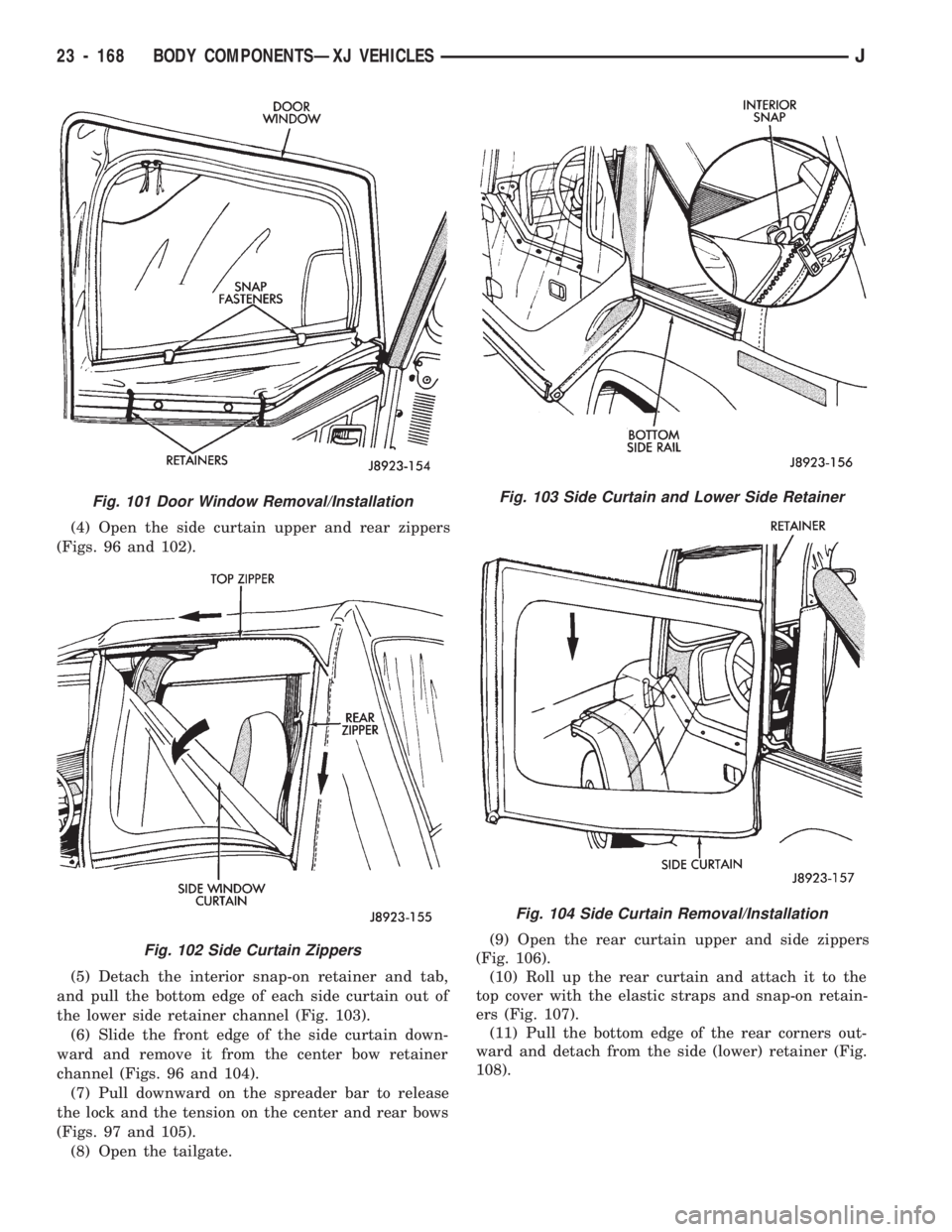
(4) Open the side curtain upper and rear zippers
(Figs. 96 and 102).
(5) Detach the interior snap-on retainer and tab,
and pull the bottom edge of each side curtain out of
the lower side retainer channel (Fig. 103).
(6) Slide the front edge of the side curtain down-
ward and remove it from the center bow retainer
channel (Figs. 96 and 104).
(7) Pull downward on the spreader bar to release
the lock and the tension on the center and rear bows
(Figs. 97 and 105).
(8) Open the tailgate.(9) Open the rear curtain upper and side zippers
(Fig. 106).
(10) Roll up the rear curtain and attach it to the
top cover with the elastic straps and snap-on retain-
ers (Fig. 107).
(11) Pull the bottom edge of the rear corners out-
ward and detach from the side (lower) retainer (Fig.
108).
Fig. 101 Door Window Removal/Installation
Fig. 102 Side Curtain Zippers
Fig. 103 Side Curtain and Lower Side Retainer
Fig. 104 Side Curtain Removal/Installation
23 - 168 BODY COMPONENTSÐXJ VEHICLESJ
Page 1626 of 1784
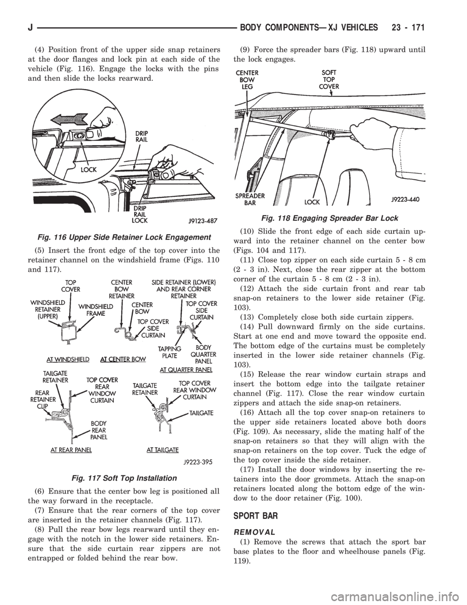
(4) Position front of the upper side snap retainers
at the door flanges and lock pin at each side of the
vehicle (Fig. 116). Engage the locks with the pins
and then slide the locks rearward.
(5) Insert the front edge of the top cover into the
retainer channel on the windshield frame (Figs. 110
and 117).
(6) Ensure that the center bow leg is positioned all
the way forward in the receptacle.
(7) Ensure that the rear corners of the top cover
are inserted in the retainer channels (Fig. 117).
(8) Pull the rear bow legs rearward until they en-
gage with the notch in the lower side retainers. En-
sure that the side curtain rear zippers are not
entrapped or folded behind the rear bow.(9) Force the spreader bars (Fig. 118) upward until
the lock engages.
(10) Slide the front edge of each side curtain up-
ward into the retainer channel on the center bow
(Figs. 104 and 117).
(11) Close top zipper on each side curtain5-8cm
(2 - 3 in). Next, close the rear zipper at the bottom
corner of the curtain5-8cm(2-3in).
(12) Attach the side curtain front and rear tab
snap-on retainers to the lower side retainer (Fig.
103).
(13) Completely close both side curtain zippers.
(14) Pull downward firmly on the side curtains.
Start at one end and move toward the opposite end.
The bottom edge of the curtains must be completely
inserted in the lower side retainer channels (Fig.
103).
(15) Release the rear window curtain straps and
insert the bottom edge into the tailgate retainer
channel (Fig. 117). Close the rear window curtain
zippers and attach the side snap-on retainers.
(16) Attach all the top cover snap-on retainers to
the upper side retainers located above both doors
(Fig. 109). As necessary, slide the mating half of the
snap-on retainers so that they will align with the
snap-on retainers on the top cover. Tuck the edge of
the top cover inside the side retainer.
(17) Install the door windows by inserting the re-
tainers into the door grommets. Attach the snap-on
retainers located along the bottom edge of the win-
dow to the door retainer (Fig. 100).
SPORT BAR
REMOVAL
(1) Remove the screws that attach the sport bar
base plates to the floor and wheelhouse panels (Fig.
119).
Fig. 116 Upper Side Retainer Lock Engagement
Fig. 117 Soft Top Installation
Fig. 118 Engaging Spreader Bar Lock
JBODY COMPONENTSÐXJ VEHICLES 23 - 171
Page 1628 of 1784
DOORS
INDEX
page page
Full-Metal Door Assist Handle.............. 175
Full-Metal Door Hinges................... 179
Full-Metal Door Key Lock Cylinder........... 178
Full-Metal Door Latch.................... 179
Full-Metal Door Latch External Release Handle . 178
Full-Metal Door Latch Inside Release and
Lock Handle.......................... 175
Full-Metal Door Service................... 181
Full-Metal Door Trim Panel................ 175Full-Metal Door Vent Window Glass......... 177
Full-Metal Door Waterdam................. 176
Full-Metal Door Weatherstrip Seals.......... 180
Full-Metal Door Window Glass.............. 178
Full-Metal Door Window Glass Regulator...... 177
Full-Metal Door Window Glass Regulator Handle. 175
Half-Metal Door Latch Striker............... 175
Half-Metal Soft Top Door.................. 173
HALF-METAL SOFT TOP DOOR
REMOVAL/DISASSEMBLY
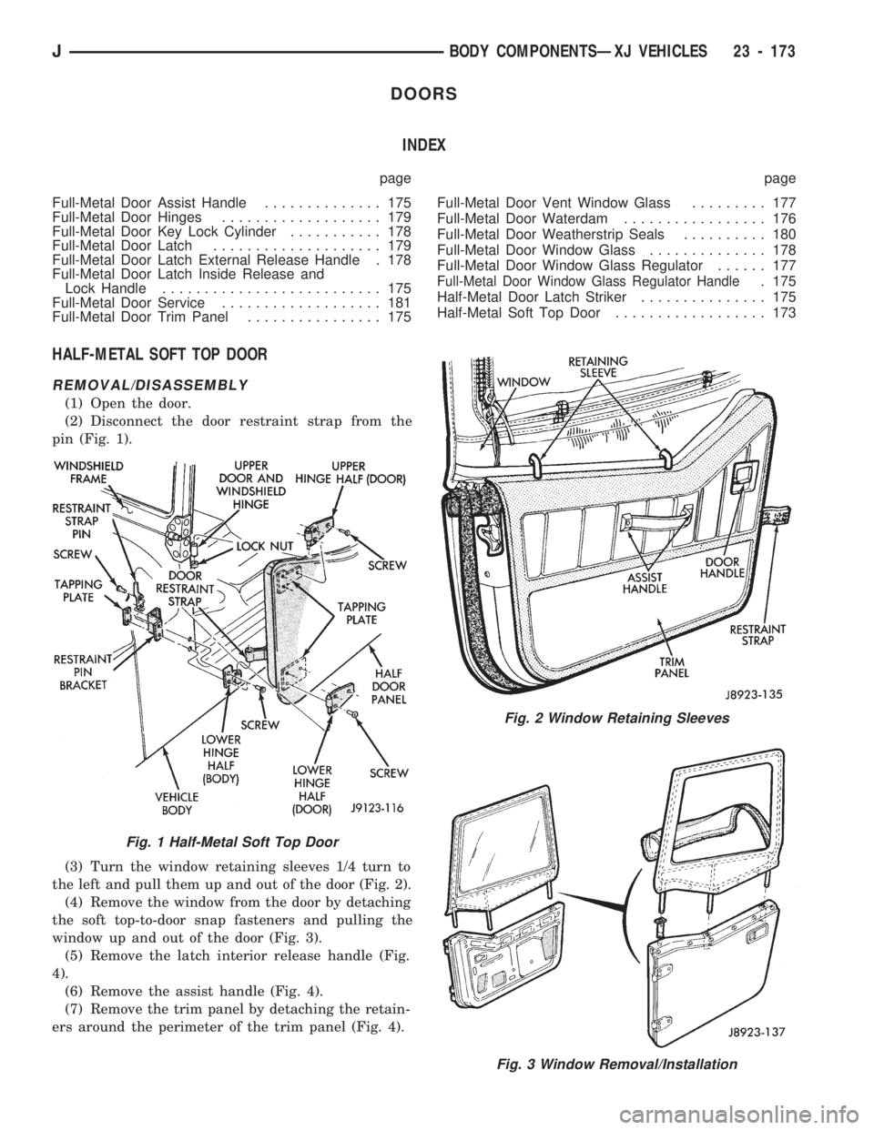
(1) Open the door.
(2) Disconnect the door restraint strap from the
pin (Fig. 1).
(3) Turn the window retaining sleeves 1/4 turn to
the left and pull them up and out of the door (Fig. 2).
(4) Remove the window from the door by detaching
the soft top-to-door snap fasteners and pulling the
window up and out of the door (Fig. 3).
(5) Remove the latch interior release handle (Fig.
4).
(6) Remove the assist handle (Fig. 4).
(7) Remove the trim panel by detaching the retain-
ers around the perimeter of the trim panel (Fig. 4).
Fig. 2 Window Retaining Sleeves
Fig. 3 Window Removal/Installation
Fig. 1 Half-Metal Soft Top Door
JBODY COMPONENTSÐXJ VEHICLES 23 - 173
Page 1630 of 1784
(6) Install the interior trim panel (Fig. 4).
(7) Connect the latch release rod to the door latch
interior release handle and install the handle (Fig.
4).
(8) Install the assist handle (Fig. 4).
(9) Install the window retaining sleeves (Fig. 2).
(10) Install the window (Fig. 1).
(11) Attach the restraint strap to the pin (Fig. 1).
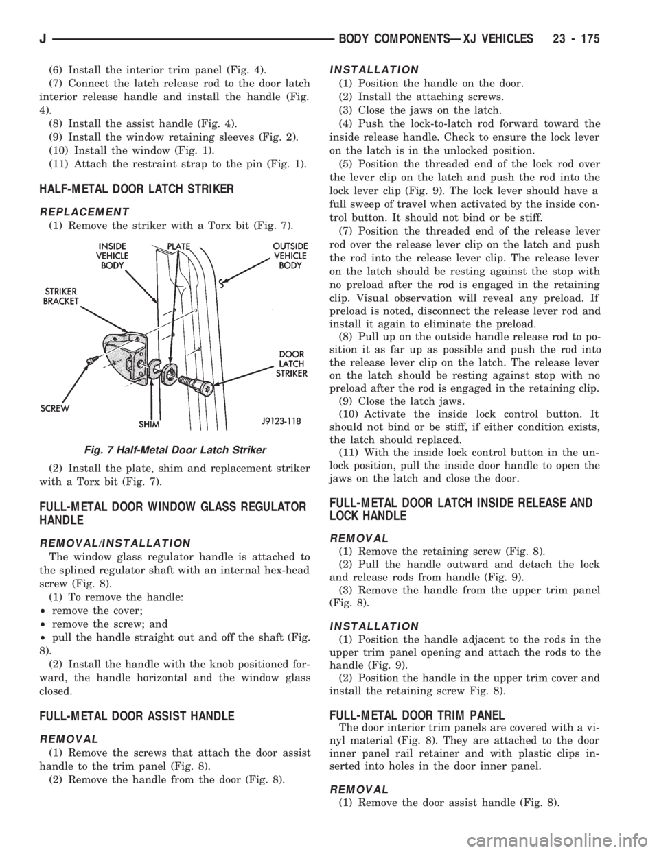
HALF-METAL DOOR LATCH STRIKER
REPLACEMENT
(1) Remove the striker with a Torx bit (Fig. 7).
(2) Install the plate, shim and replacement striker
with a Torx bit (Fig. 7).
FULL-METAL DOOR WINDOW GLASS REGULATOR
HANDLE
REMOVAL/INSTALLATION
The window glass regulator handle is attached to
the splined regulator shaft with an internal hex-head
screw (Fig. 8).
(1) To remove the handle:
²remove the cover;
²remove the screw; and
²pull the handle straight out and off the shaft (Fig.
8).
(2) Install the handle with the knob positioned for-
ward, the handle horizontal and the window glass
closed.
FULL-METAL DOOR ASSIST HANDLE
REMOVAL
(1) Remove the screws that attach the door assist
handle to the trim panel (Fig. 8).
(2) Remove the handle from the door (Fig. 8).
INSTALLATION
(1) Position the handle on the door.
(2) Install the attaching screws.
(3) Close the jaws on the latch.
(4) Push the lock-to-latch rod forward toward the
inside release handle. Check to ensure the lock lever
on the latch is in the unlocked position.
(5) Position the threaded end of the lock rod over
the lever clip on the latch and push the rod into the
lock lever clip (Fig. 9). The lock lever should have a
full sweep of travel when activated by the inside con-
trol button. It should not bind or be stiff.
(7) Position the threaded end of the release lever
rod over the release lever clip on the latch and push
the rod into the release lever clip. The release lever
on the latch should be resting against the stop with
no preload after the rod is engaged in the retaining
clip. Visual observation will reveal any preload. If
preload is noted, disconnect the release lever rod and
install it again to eliminate the preload.
(8) Pull up on the outside handle release rod to po-
sition it as far up as possible and push the rod into
the release lever clip on the latch. The release lever
on the latch should be resting against stop with no
preload after the rod is engaged in the retaining clip.
(9) Close the latch jaws.
(10) Activate the inside lock control button. It
should not bind or be stiff, if either condition exists,
the latch should replaced.
(11) With the inside lock control button in the un-
lock position, pull the inside door handle to open the
jaws on the latch and close the door.
FULL-METAL DOOR LATCH INSIDE RELEASE AND
LOCK HANDLE
REMOVAL
(1) Remove the retaining screw (Fig. 8).
(2) Pull the handle outward and detach the lock
and release rods from handle (Fig. 9).
(3) Remove the handle from the upper trim panel
(Fig. 8).
INSTALLATION
(1) Position the handle adjacent to the rods in the
upper trim panel opening and attach the rods to the
handle (Fig. 9).
(2) Position the handle in the upper trim cover and
install the retaining screw Fig. 8).
FULL-METAL DOOR TRIM PANEL
The door interior trim panels are covered with a vi-
nyl material (Fig. 8). They are attached to the door
inner panel rail retainer and with plastic clips in-
serted into holes in the door inner panel.
REMOVAL
(1) Remove the door assist handle (Fig. 8).
Fig. 7 Half-Metal Door Latch Striker
JBODY COMPONENTSÐXJ VEHICLES 23 - 175
Page 1631 of 1784
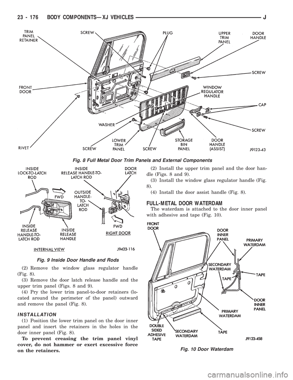
(2) Remove the window glass regulator handle
(Fig. 8).
(3) Remove the door latch release handle and the
upper trim panel (Figs. 8 and 9).
(4) Pry the lower trim panel-to-door retainers (lo-
cated around the perimeter of the panel) outward
and remove the panel (Fig. 8).
INSTALLATION
(1) Position the lower trim panel on the door inner
panel and insert the retainers in the holes in the
door inner panel (Fig. 8).
To prevent creasing the trim panel vinyl
cover, do not hammer or exert excessive force
on the retainers.(2) Install the upper trim panel and the door han-
dle (Figs. 8 and 9).
(3) Install the window glass regulator handle (Fig.
8).
(4) Install the door assist handle (Fig. 8).
FULL-METAL DOOR WATERDAM
The waterdam is attached to the door inner panel
with adhesive and tape (Fig. 10).
Fig. 10 Door Waterdam
Fig. 8 Full Metal Door Trim Panels and External Components
Fig. 9 Inside Door Handle and Rods
23 - 176 BODY COMPONENTSÐXJ VEHICLESJ
Page 1632 of 1784
REMOVAL/INSTALLATION
(1) To remove a waterdam, insert a putty knife be-
tween it and the door inner panel.
(2) When installing a waterdam, ensure that lower
portion of waterdam is tucked inside the door panel
at the access opening.
FULL-METAL DOOR VENT WINDOW GLASS
REMOVAL
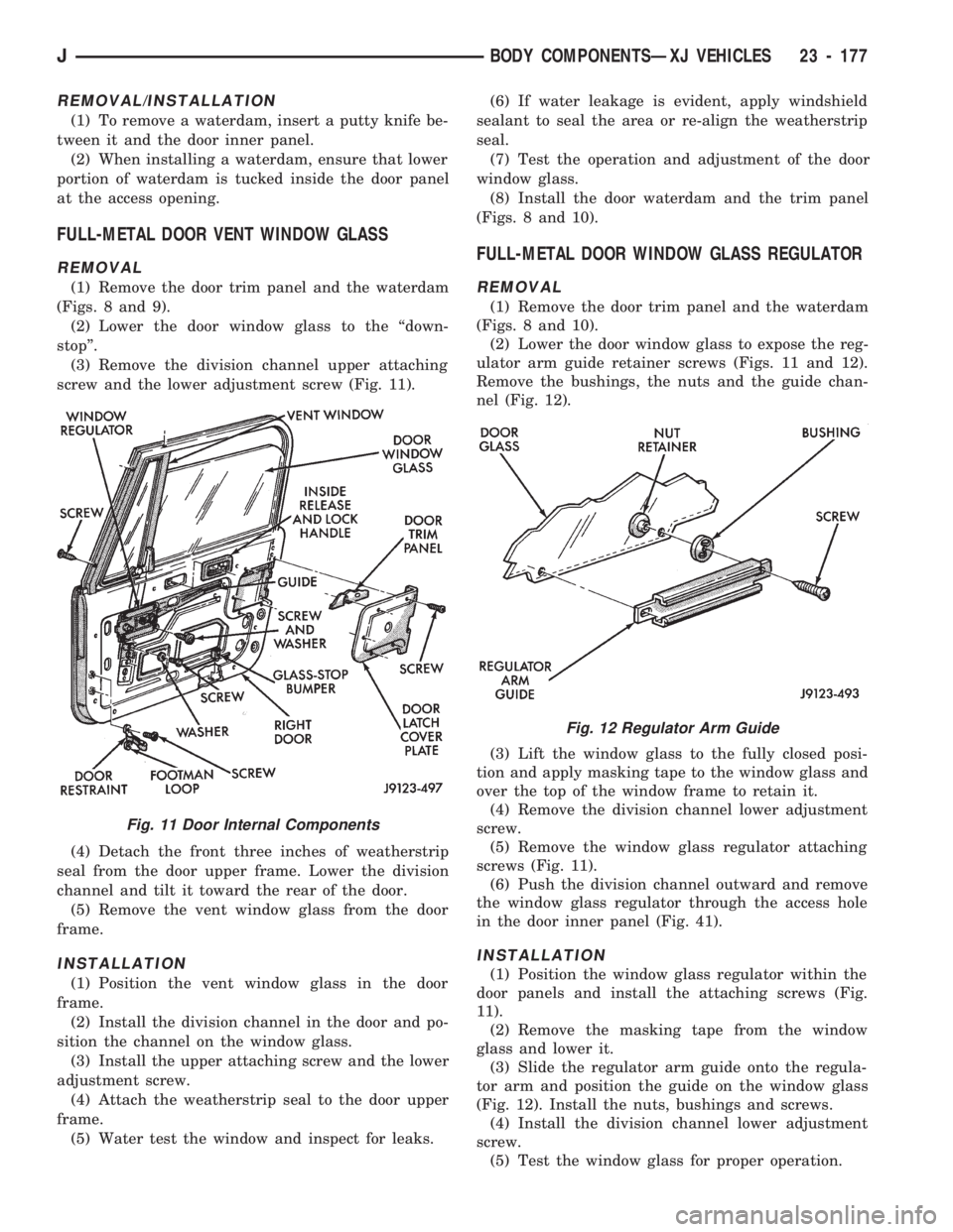
(1) Remove the door trim panel and the waterdam
(Figs. 8 and 9).
(2) Lower the door window glass to the ``down-
stop''.
(3) Remove the division channel upper attaching
screw and the lower adjustment screw (Fig. 11).
(4) Detach the front three inches of weatherstrip
seal from the door upper frame. Lower the division
channel and tilt it toward the rear of the door.
(5) Remove the vent window glass from the door
frame.
INSTALLATION
(1) Position the vent window glass in the door
frame.
(2) Install the division channel in the door and po-
sition the channel on the window glass.
(3) Install the upper attaching screw and the lower
adjustment screw.
(4) Attach the weatherstrip seal to the door upper
frame.
(5) Water test the window and inspect for leaks.(6) If water leakage is evident, apply windshield
sealant to seal the area or re-align the weatherstrip
seal.
(7) Test the operation and adjustment of the door
window glass.
(8) Install the door waterdam and the trim panel
(Figs. 8 and 10).
FULL-METAL DOOR WINDOW GLASS REGULATOR
REMOVAL
(1) Remove the door trim panel and the waterdam
(Figs. 8 and 10).
(2) Lower the door window glass to expose the reg-
ulator arm guide retainer screws (Figs. 11 and 12).
Remove the bushings, the nuts and the guide chan-
nel (Fig. 12).
(3) Lift the window glass to the fully closed posi-
tion and apply masking tape to the window glass and
over the top of the window frame to retain it.
(4) Remove the division channel lower adjustment
screw.
(5) Remove the window glass regulator attaching
screws (Fig. 11).
(6) Push the division channel outward and remove
the window glass regulator through the access hole
in the door inner panel (Fig. 41).
INSTALLATION
(1) Position the window glass regulator within the
door panels and install the attaching screws (Fig.
11).
(2) Remove the masking tape from the window
glass and lower it.
(3) Slide the regulator arm guide onto the regula-
tor arm and position the guide on the window glass
(Fig. 12). Install the nuts, bushings and screws.
(4) Install the division channel lower adjustment
screw.
(5) Test the window glass for proper operation.
Fig. 11 Door Internal Components
Fig. 12 Regulator Arm Guide
JBODY COMPONENTSÐXJ VEHICLES 23 - 177