1994 JEEP CHEROKEE window
[x] Cancel search: windowPage 1512 of 1784
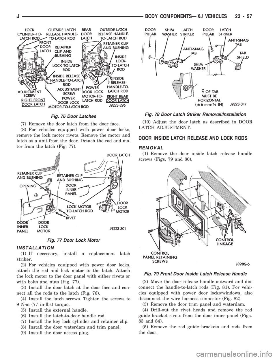
(7) Remove the door latch from the door face.
(8) For vehicles equipped with power door locks,
remove the lock motor rivets. Remove the motor and
latch as a unit from the door. Detach the rod and mo-
tor from the latch (Fig. 77).
INSTALLATION
(1) If necessary, install a replacement latch
striker.
(2) For vehicles equipped with power door locks,
attach the rod and lock motor to the latch. Attach
the lock motor to the door panel with either rivets or
with bolts and nuts (Fig. 77).
(3) Install the door latch at the door face and con-
nect all the rods to the latch (Fig. 76).
(4) Install the latch screws. Tighten the screws to
9Nzm (77 in-lbs) torque.
(5) Install the external handle.
(6) Install the latch-to-door handle rod.
(7) Install the key lock cylinder and retainer clip.
(8) Install the door waterdam and trim panel.
(9) Install the door access plug.(10) Adjust the door latch as described in DOOR
LATCH ADJUSTMENT.
DOOR INSIDE LATCH RELEASE AND LOCK RODS
REMOVAL
(1) Remove the door inside latch release handle
screws (Figs. 79 and 80).
(2) Move the door release handle outward and dis-
connect the handle-to-latch rods (Fig. 81). For vehi-
cles equipped with power door locks/windows, also
disconnect the wire harness connector (Fig. 82).
(3) Remove the door trim panel and waterdam.
(4) Drill-out the rivet heads and remove the rod
guide bracket rivets from the door inner panel (Figs.
83 and 84).
(5) Remove the rod guide brackets and rods from
the door.
Fig. 76 Door Latches
Fig. 77 Door Lock Motor
Fig. 78 Door Latch Striker Removal/Installation
Fig. 79 Front Door Inside Latch Release Handle
JBODY COMPONENTSÐXJ VEHICLES 23 - 57
Page 1515 of 1784
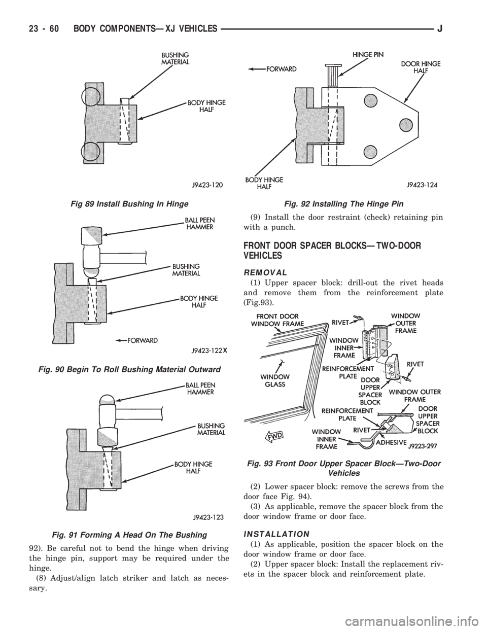
92). Be careful not to bend the hinge when driving
the hinge pin, support may be required under the
hinge.
(8) Adjust/align latch striker and latch as neces-
sary.(9) Install the door restraint (check) retaining pin
with a punch.
FRONT DOOR SPACER BLOCKSÐTWO-DOOR
VEHICLES
REMOVAL
(1) Upper spacer block: drill-out the rivet heads
and remove them from the reinforcement plate
(Fig.93).
(2) Lower spacer block: remove the screws from the
door face Fig. 94).
(3) As applicable, remove the spacer block from the
door window frame or door face.
INSTALLATION
(1) As applicable, position the spacer block on the
door window frame or door face.
(2) Upper spacer block: Install the replacement riv-
ets in the spacer block and reinforcement plate.
Fig 89 Install Bushing In Hinge
Fig. 90 Begin To Roll Bushing Material Outward
Fig. 91 Forming A Head On The Bushing
Fig. 92 Installing The Hinge Pin
Fig. 93 Front Door Upper Spacer BlockÐTwo-Door
Vehicles
23 - 60 BODY COMPONENTSÐXJ VEHICLESJ
Page 1516 of 1784
(3) Lower spacer block: install the screws in the
door face. Tighten the screws to 1 Nzm (11 in-lbs)
torque.
DOOR EDGE GUARD/EDGE PROTECTOR STRIP
REPLACEMENT
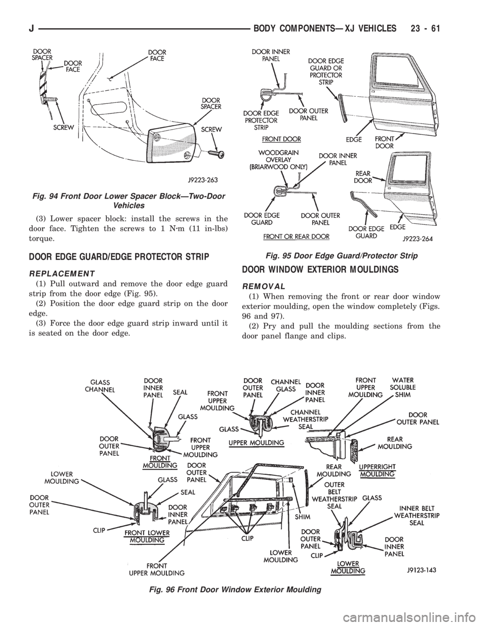
(1) Pull outward and remove the door edge guard
strip from the door edge (Fig. 95).
(2) Position the door edge guard strip on the door
edge.
(3) Force the door edge guard strip inward until it
is seated on the door edge.
DOOR WINDOW EXTERIOR MOULDINGS
REMOVAL
(1) When removing the front or rear door window
exterior moulding, open the window completely (Figs.
96 and 97).
(2) Pry and pull the moulding sections from the
door panel flange and clips.
Fig. 95 Door Edge Guard/Protector Strip
Fig. 96 Front Door Window Exterior Moulding
Fig. 94 Front Door Lower Spacer BlockÐTwo-Door
Vehicles
JBODY COMPONENTSÐXJ VEHICLES 23 - 61
Page 1517 of 1784
INSTALLATION
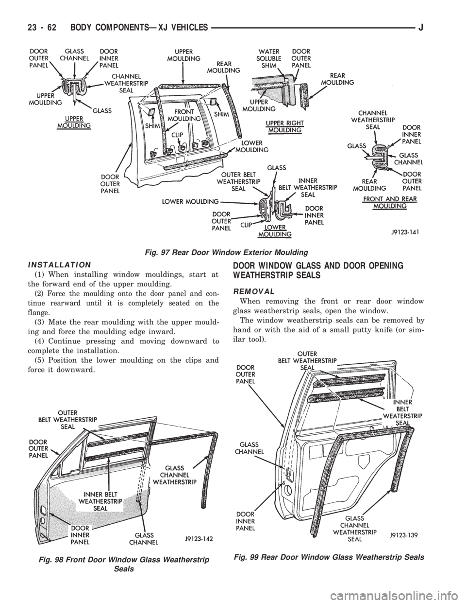
(1) When installing window mouldings, start at
the forward end of the upper moulding.
(2) Force the moulding onto the door panel and con-
tinue rearward until it is completely seated on the
flange.
(3) Mate the rear moulding with the upper mould-
ing and force the moulding edge inward.
(4) Continue pressing and moving downward to
complete the installation.
(5) Position the lower moulding on the clips and
force it downward.
DOOR WINDOW GLASS AND DOOR OPENING
WEATHERSTRIP SEALS
REMOVAL
When removing the front or rear door window
glass weatherstrip seals, open the window.
The window weatherstrip seals can be removed by
hand or with the aid of a small putty knife (or sim-
ilar tool).
Fig. 97 Rear Door Window Exterior Moulding
Fig. 98 Front Door Window Glass Weatherstrip
SealsFig. 99 Rear Door Window Glass Weatherstrip Seals
23 - 62 BODY COMPONENTSÐXJ VEHICLESJ
Page 1518 of 1784
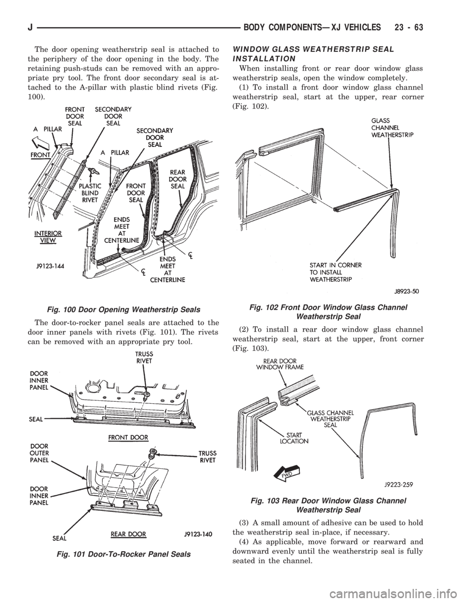
The door opening weatherstrip seal is attached to
the periphery of the door opening in the body. The
retaining push-studs can be removed with an appro-
priate pry tool. The front door secondary seal is at-
tached to the A-pillar with plastic blind rivets (Fig.
100).
The door-to-rocker panel seals are attached to the
door inner panels with rivets (Fig. 101). The rivets
can be removed with an appropriate pry tool.WINDOW GLASS WEATHERSTRIP SEAL
INSTALLATION
When installing front or rear door window glass
weatherstrip seals, open the window completely.
(1) To install a front door window glass channel
weatherstrip seal, start at the upper, rear corner
(Fig. 102).
(2) To install a rear door window glass channel
weatherstrip seal, start at the upper, front corner
(Fig. 103).
(3) A small amount of adhesive can be used to hold
the weatherstrip seal in-place, if necessary.
(4) As applicable, move forward or rearward and
downward evenly until the weatherstrip seal is fully
seated in the channel.
Fig. 100 Door Opening Weatherstrip Seals
Fig. 101 Door-To-Rocker Panel Seals
Fig. 102 Front Door Window Glass Channel
Weatherstrip Seal
Fig. 103 Rear Door Window Glass Channel
Weatherstrip Seal
JBODY COMPONENTSÐXJ VEHICLES 23 - 63
Page 1528 of 1784
FIXED WINDOW GLASS
INDEX
page page
Fixed Glass Water Leak Detection and Repair . . 83
Interior Rearview Mirror.................... 74
Interior Rearview Mirror Support Bracket
Replacement.......................... 75
Liftgate Window GlassÐXJ Vehicles.......... 81
Rear Quarter Vent Window GlassÐXJ Vehicles . 80Rear Quarter Window Glass/Rear Quarter
Plastic Insert ÐXJ Vehicles............... 80
Service Information....................... 73
Windshield Glass Replacement.............. 75
Windshield Reveal Moulding................ 73
Windshield Service Information.............. 75
SERVICE INFORMATION
The following service procedures include removal
and installation of the:
²windshield reveal moulding,
²interior rearview mirror,
²windshield glass (using both the short and the ex-
tended installation method),
²rear quarter vent window glass,
²rear quarter window glass,
²liftgate window glass,
²cab rear window, and
²leak detection and repair.
WINDSHIELD REVEAL MOULDING
REMOVAL
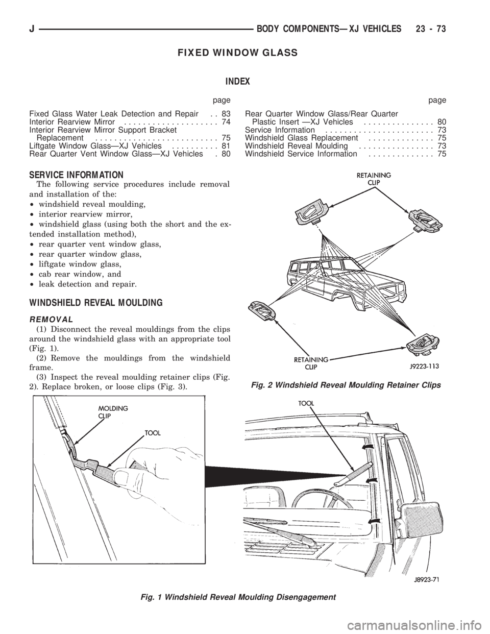
(1) Disconnect the reveal mouldings from the clips
around the windshield glass with an appropriate tool
(Fig. 1).
(2) Remove the mouldings from the windshield
frame.
(3) Inspect the reveal moulding retainer clips (Fig.
2). Replace broken, or loose clips (Fig. 3).
Fig. 1 Windshield Reveal Moulding Disengagement
Fig. 2 Windshield Reveal Moulding Retainer Clips
JBODY COMPONENTSÐXJ VEHICLES 23 - 73
Page 1533 of 1784
CAUTION: Avoid spilling or dripping primer on
painted surfaces. Clean spills or drips immediately.
The primer will damage the paint if it remains on
the surface for any length of time.
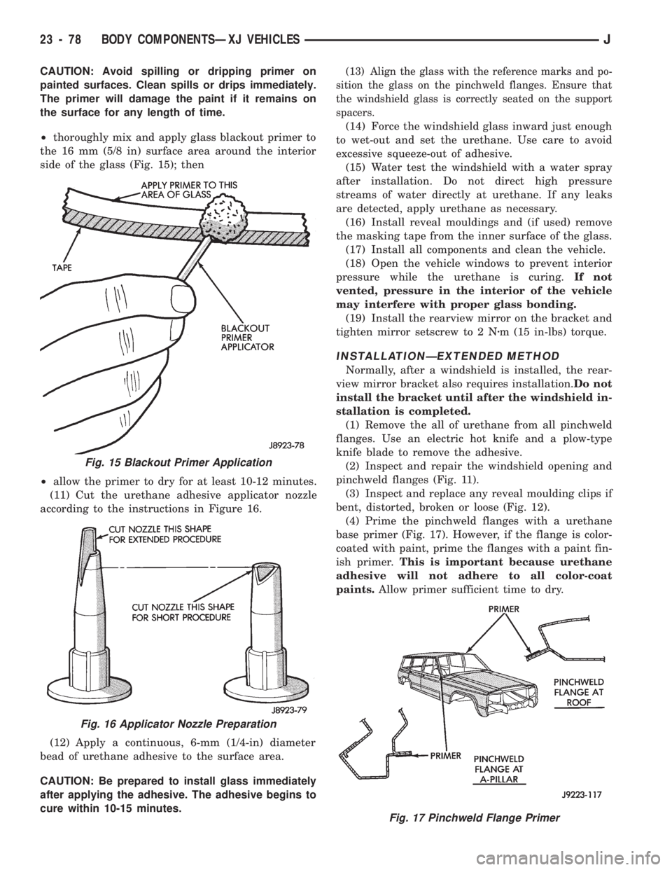
²thoroughly mix and apply glass blackout primer to
the 16 mm (5/8 in) surface area around the interior
side of the glass (Fig. 15); then
²allow the primer to dry for at least 10-12 minutes.
(11) Cut the urethane adhesive applicator nozzle
according to the instructions in Figure 16.
(12) Apply a continuous, 6-mm (1/4-in) diameter
bead of urethane adhesive to the surface area.
CAUTION: Be prepared to install glass immediately
after applying the adhesive. The adhesive begins to
cure within 10-15 minutes.(13) Align the glass with the reference marks and po-
sition the glass on the pinchweld flanges. Ensure that
the windshield glass is correctly seated on the support
spacers.
(14) Force the windshield glass inward just enough
to wet-out and set the urethane. Use care to avoid
excessive squeeze-out of adhesive.
(15) Water test the windshield with a water spray
after installation. Do not direct high pressure
streams of water directly at urethane. If any leaks
are detected, apply urethane as necessary.
(16) Install reveal mouldings and (if used) remove
the masking tape from the inner surface of the glass.
(17) Install all components and clean the vehicle.
(18) Open the vehicle windows to prevent interior
pressure while the urethane is curing.If not
vented, pressure in the interior of the vehicle
may interfere with proper glass bonding.
(19) Install the rearview mirror on the bracket and
tighten mirror setscrew to 2 Nzm (15 in-lbs) torque.
INSTALLATIONÐEXTENDED METHOD
Normally, after a windshield is installed, the rear-
view mirror bracket also requires installation.Do not
install the bracket until after the windshield in-
stallation is completed.
(1) Remove the all of urethane from all pinchweld
flanges. Use an electric hot knife and a plow-type
knife blade to remove the adhesive.
(2) Inspect and repair the windshield opening and
pinchweld flanges (Fig. 11).
(3) Inspect and replace any reveal moulding clips if
bent, distorted, broken or loose (Fig. 12).
(4) Prime the pinchweld flanges with a urethane
base primer (Fig. 17). However, if the flange is color-
coated with paint, prime the flanges with a paint fin-
ish primer.This is important because urethane
adhesive will not adhere to all color-coat
paints.Allow primer sufficient time to dry.
Fig. 15 Blackout Primer Application
Fig. 16 Applicator Nozzle Preparation
Fig. 17 Pinchweld Flange Primer
23 - 78 BODY COMPONENTSÐXJ VEHICLESJ
Page 1534 of 1784
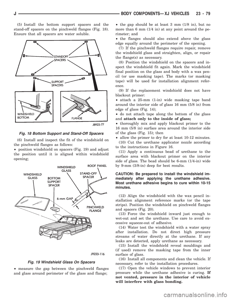
(5) Install the bottom support spacers and the
stand-off spacers on the pinchweld flanges (Fig. 18).
Ensure that all spacers are water soluble.
(6) Install and inspect the fit of the windshield on
the pinchweld flanges as follows:
²position windshield on spacers (Fig. 19) and adjust
the position until it is aligned within windshield
opening;
²measure the gap between the pinchweld flanges
and glass around perimeter of the glass and flange;²the gap should be at least 3 mm (1/8 in), but no
more than 6 mm (1/4 in) at any point around the pe-
rimeter; and
²the flanges should also extend above the glass
edge equally around the perimeter of the opening.
(7) If the pinchweld flanges require repair, remove
the windshield glass and straighten, align, or repair
the flange(s) as necessary.
(8) Position the windshield on the spacers and in-
spect the windshield fit again. Mark the windshield
final position on the glass and body with a wax pen-
cil (or use masking tape). The marks (or masking
tape) will be used for installation alignment refer-
ence.
(9) If the replacement windshield does not have
blackout primer:
²attach a 25-mm (1-in) wide masking tape band
around the interior side of glass 16 mm (5/8 in) from
edge of glass (Fig. 14);
²do not attach tape along the bottom of the glass
andattach only to the inside of glass;
²thoroughly mix and apply blackout primer to the
16 mm (5/8 in) surface area around the interior side
of the glass (Fig. 15); then
²allow the primer to dry for at least 10-12 minutes.
(10) Cut the urethane applicator nozzle according
to the instructions in Figure 16.
(11) Apply a continuous bead of urethane to the
surface area with blackout primer on the interior
side of glass. The bead should be 6-mm (1/4-in) wide
by 9-mm (3/8-in) deep for best results.
CAUTION: Be prepared to install the windshield im-
mediately after applying the urethane adhesive.
Most urethane adhesive begins to cure within 10-15
minutes.
(12) Align the windshield with the wax pencil in-
stallation alignment reference marks (or the tape
strips). Position the windshield on pinchweld flanges
and spacers (Fig. 20).
(13) Force the windshield inward just enough to
wet-out and set the urethane. Use care to avoid ex-
cessive squeeze-out of adhesive.
(14) Water test the windshield with a water spray
after installation. Do not direct high pressure
streams of water directly at the urethane. If any
leaks are detected, apply urethane as necessary.
(15) Install the windshield reveal mouldings and
(if used) remove the masking tape from the inner
surface of glass.
(16) Install all components and clean the vehicle. If
necessary, refer to the installation procedures.
(17) Open the vehicle windows to prevent interior
pressure while the urethane adhesive is curing.If
not vented, pressure in the interior of vehicle
will interfere with glass bonding.
Fig. 18 Bottom Support and Stand-Off Spacers
Fig. 19 Windshield Glass On Spacers
JBODY COMPONENTSÐXJ VEHICLES 23 - 79