1994 JEEP CHEROKEE window
[x] Cancel search: windowPage 454 of 1784
²Measure voltage at relay connector terminal 4.
The meter should read battery voltage. If not, repair
open to fuse #18 (XJ), or fuse #9 (YJ).
²Measure voltage at relay connector terminal 5.
The meter should read battery voltage. If not, repair
open from #8 fuse XJ, or fuse #6 YJ.
²Measure resistance between relay connector termi-
nal 1 and left side (driver's side) of defogger grid.
The meter should read zero ohms. If not, repair open
between relay connector and left side of defogger
grid.
²Measure resistance between relay connector termi-
nal 2 and a clean chassis ground. The meter should
read zero ohms. If not, repair open between relay
connector and ground.
²Connect relay connector and measure voltage at
terminal 3. The meter should read approximately 5volts. If not, replace defogger relay.
INDICATOR LAMP
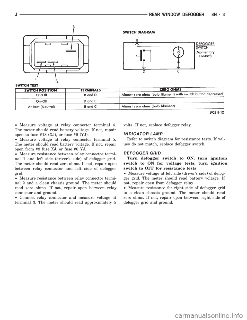
Refer to switch diagram for resistance tests. If val-
ues do not match, replace defogger switch.
DEFOGGER GRID
Turn defogger switch to ON; turn ignition
switch to ON for voltage tests; turn ignition
switch to OFF for resistance tests
²Measure voltage at left side (driver's side) of defog-
ger grid. The meter should read battery voltage. If
not, repair open from defogger relay.
²Measure resistance for right side of defogger grid
to a clean chassis ground. The meter should read
zero ohms. If not, repair open between right side of
defogger grid and ground.
JREAR WINDOW DEFOGGER 8N - 3
Page 455 of 1784
XJ
REAR WINDOW DEFOGGER SWITCH
REPLACEMENT
(1) Remove the instrument panel bezel; see 8E-In-
strument Panel and Gauges section for the proce-
dure.
(2) Remove the switch housing panel.
(3) Unplug the switch connector. Slightly depress
the switch mounting tabs and remove the switch.
REAR DEFOGGER RELAY
The rear defogger relay is in the relay center. The
relay center is located on the lower instrument panel
trim cover just right of the steering column.
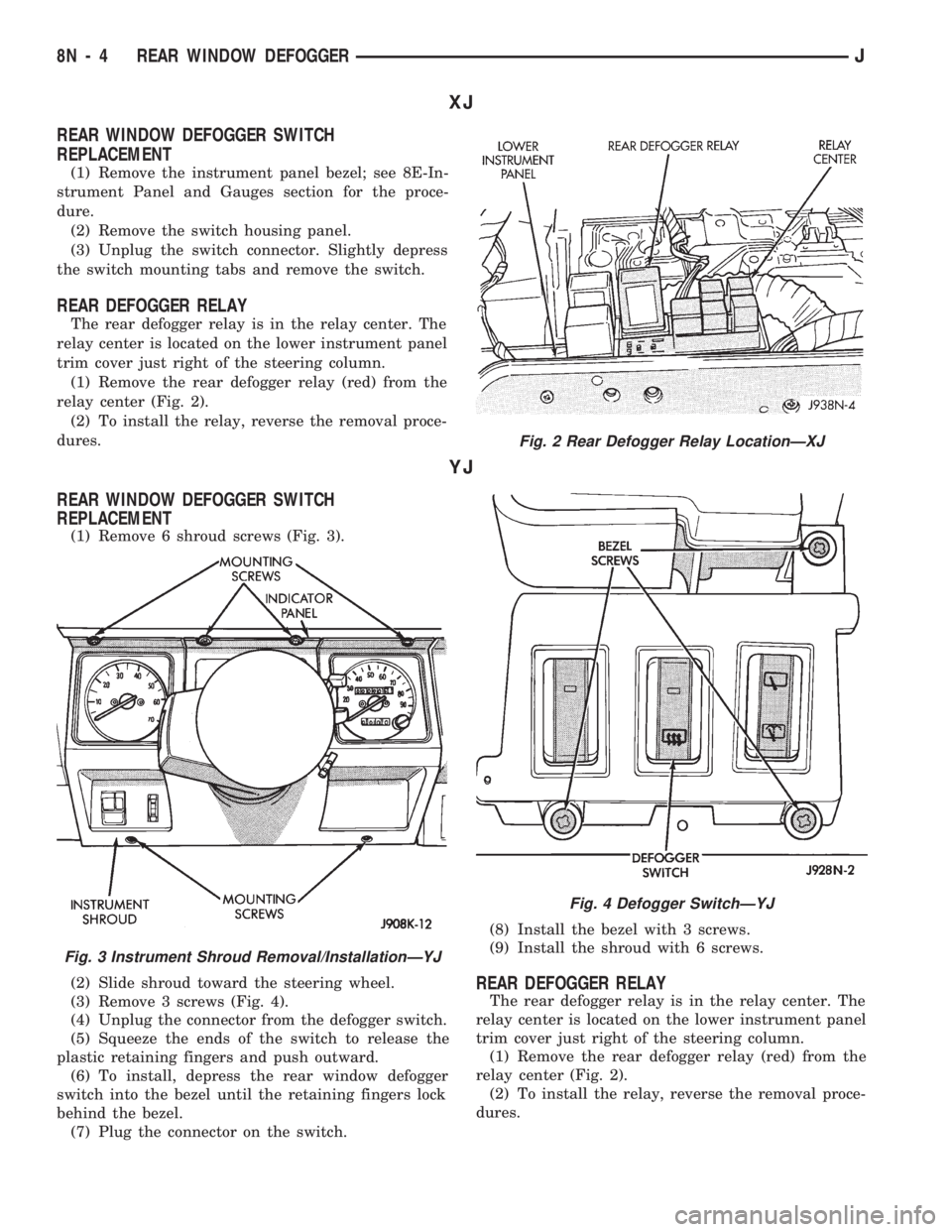
(1) Remove the rear defogger relay (red) from the
relay center (Fig. 2).
(2) To install the relay, reverse the removal proce-
dures.
YJ
REAR WINDOW DEFOGGER SWITCH
REPLACEMENT
(1) Remove 6 shroud screws (Fig. 3).
(2) Slide shroud toward the steering wheel.
(3) Remove 3 screws (Fig. 4).
(4) Unplug the connector from the defogger switch.
(5) Squeeze the ends of the switch to release the
plastic retaining fingers and push outward.
(6) To install, depress the rear window defogger
switch into the bezel until the retaining fingers lock
behind the bezel.
(7) Plug the connector on the switch.(8) Install the bezel with 3 screws.
(9) Install the shroud with 6 screws.
REAR DEFOGGER RELAY
The rear defogger relay is in the relay center. The
relay center is located on the lower instrument panel
trim cover just right of the steering column.
(1) Remove the rear defogger relay (red) from the
relay center (Fig. 2).
(2) To install the relay, reverse the removal proce-
dures.
Fig. 2 Rear Defogger Relay LocationÐXJ
Fig. 3 Instrument Shroud Removal/InstallationÐYJ
Fig. 4 Defogger SwitchÐYJ
8N - 4 REAR WINDOW DEFOGGERJ
Page 456 of 1784
POWER DOOR LOCKS
CONTENTS
page page
KEYLESS ENTRY........................ 8POWER LOCKS......................... 1
POWER LOCKS
INDEX
page page
Actuator Motor Stall Test.................... 6
Description.............................. 1
Diagnosing Power Door Locks............... 1
General................................. 1Liftgate Lock Cylinder Replacement............ 7
Solenoid and Latch Assembly Replacement..... 6
Switch Replacement....................... 6
GENERAL
The door lock actuators, including liftgate, are con-
trolled by two-way switches. To lock the doors, push
down on either switch. To unlock doors from inside
the vehicle push upward on either switch.
The power door locks do not lock or unlock the
doors from outside the vehicle. Insert the key into
the lock cylinder to lock or unlock each individual
door.
DESCRIPTION
The door locks are operated by reversible motors
that receive voltage from fuse #13 in the fuse panel.
Voltage is applied to the driver's side door lock
switch and the passenger's side door lock switch
through the #9 fuse. With the driver's side door lock
switch in LOCK, voltage is applied through the
switch to the door lock relay coil. The relay coil is
energized which closes the circuit from the circuit
breaker to the lock motor. The motor is grounded by
the unlock relay.
The passenger's side door lock window switch oper-
ates the same as the driver's door switch. The volt-
age and ground paths are reversed to unlock the
doors.
The power door lock operates with battery power
and, therefore, is independent of the ignition switch.
DIAGNOSING POWER DOOR LOCKS
If vehicle has Keyless Entry and the door locks op-
erate properly using door switches but do not work
with transmitter, refer to Keyless Entry in this
group.
NO DOOR LOCKS OPERATE USING DOOR
LOCK SWITCHES
(1) Inspect fuse #13. Replace if necessary. If OK,
measure voltage at battery side of fuse. There should
be 12 volts. If not, repair open from Power Distribu-
tion Center.
(2) Remove door switch and measure voltage at
terminal 1. Meter should read battery voltage. If not,
repair open to #9 fuse.
(3) The power window relays are in the relay cen-
ter. The relay center is located on the lower instru-
ment panel trim cover just right of the steering
column (Fig. 1). Remove both relays.
(4) Measure resistance between lock and unlock re-
lay terminal 4 (87A) and ground. Meter should read
zero ohms. If not, repair open to ground.
(5) Measure voltage at terminal 5 (87) of both the
lock and unlock relays. Meter should read battery
voltage. If OK, next step. If not, repair open to cir-
cuit breaker.
(6) Measure resistance at terminal 2 (85) of both
the lock and unlock relays. Meter should read zero
ohms. If not, repair open to ground.
(7) Hold driver's side switch in LOCK position.
Measure voltage at lock relay terminal 1 (86). Meter
should read battery voltage. If OK, next step. If not,
repair open to driver's side switch.
(8) Hold driver's side switch in UNLOCK position.
Measure voltage at unlock relay terminal 1 (86).
Meter should read battery voltage. If OK, next step.
If not, repair open to driver's side switch.
JPOWER DOOR LOCKS 8P - 1
Page 461 of 1784
ACTUATOR MOTOR STALL TEST
To test the actuator motor, connect an ammeter in
series with the motor and operate the door switch.
Replace the actuator motor if current draw exceeds 8
amps at room temperature or if the actuator does not
complete its travel in less than one second. Refer to
Solenoid and Latch Assembly Replacement procedures.
SWITCH REPLACEMENT
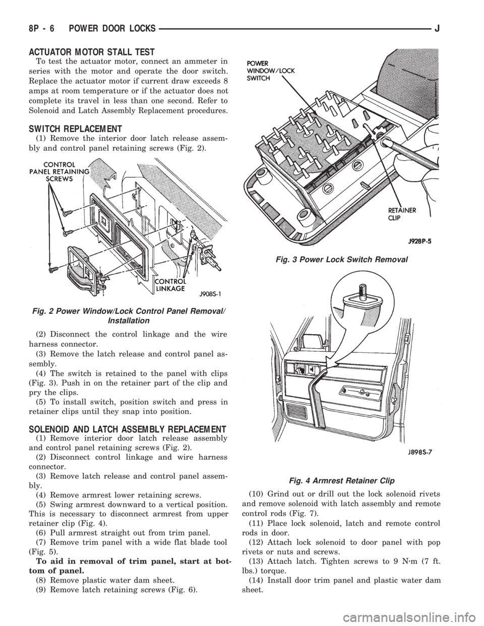
(1) Remove the interior door latch release assem-
bly and control panel retaining screws (Fig. 2).
(2) Disconnect the control linkage and the wire
harness connector.
(3) Remove the latch release and control panel as-
sembly.
(4) The switch is retained to the panel with clips
(Fig. 3). Push in on the retainer part of the clip and
pry the clips.
(5) To install switch, position switch and press in
retainer clips until they snap into position.
SOLENOID AND LATCH ASSEMBLY REPLACEMENT
(1) Remove interior door latch release assembly
and control panel retaining screws (Fig. 2).
(2) Disconnect control linkage and wire harness
connector.
(3) Remove latch release and control panel assem-
bly.
(4) Remove armrest lower retaining screws.
(5) Swing armrest downward to a vertical position.
This is necessary to disconnect armrest from upper
retainer clip (Fig. 4).
(6) Pull armrest straight out from trim panel.
(7) Remove trim panel with a wide flat blade tool
(Fig. 5).
To aid in removal of trim panel, start at bot-
tom of panel.
(8) Remove plastic water dam sheet.
(9) Remove latch retaining screws (Fig. 6).(10) Grind out or drill out the lock solenoid rivets
and remove solenoid with latch assembly and remote
control rods (Fig. 7).
(11) Place lock solenoid, latch and remote control
rods in door.
(12) Attach lock solenoid to door panel with pop
rivets or nuts and screws.
(13) Attach latch. Tighten screws to 9 Nzm(7ft.
lbs.) torque.
(14) Install door trim panel and plastic water dam
sheet.
Fig. 3 Power Lock Switch Removal
Fig. 2 Power Window/Lock Control Panel Removal/
Installation
Fig. 4 Armrest Retainer Clip
8P - 6 POWER DOOR LOCKSJ
Page 472 of 1784
POWER WINDOWS
CONTENTS
page page
DESCRIPTION........................... 1
DIAGNOSIS (Figs. 1 and 2)............... 1SWITCH TESTING....................... 5
WINDOW REGULATOR REPLACEMENT...... 9
DESCRIPTION
All XJ vehicles, equipped with power windows,
have a cable driven window regulator system. A per-
manent magnet motor moves each power window.
Each motor raises or lowers the glass when voltage
is supplied to the motor. The direction the motor
turns depends on the polarity of the supply voltage.
The control switches control the supply voltage polar-
ity.
With the ignition switch in the ON position voltage
from the 60 amp fuse in the Power Distribution Cen-
ter is applied through the power window circuit
breaker. Power then goes to the master switch termi-
nal BY and to the passenger's window switches.
When the driver's window switch is moved UP, the
contacts close a current path to:
²terminal DV
²driver's side front window motor
²terminal CV
²the DOWN contact of the driver's side front win-
dow to ground.
The motor then moves the glass up.
Current flows in a similar way when the UP con-
tact in one of the passenger's window switches is
closed. Current flow through the passenger's window
motors must go through the driver's and the passen-
ger's window switches before it reaches ground.
Each motor is protected by a built-in circuit
breaker. If a window switch is held on too long with
the window obstructed or after the window is fully
up or down, the circuit breaker opens the circuit. The
circuit breaker resets automatically as it cools. Do
not allow frequent or consecutive resetting of the cir-
cuit breaker to continue.
DIAGNOSIS (Figs. 1 and 2)
For information concerning wiring or connectors,
refer to Group 8W - Wiring Diagrams.
NO WINDOWS OPERATE
²Measure voltage at power window feed connector
at fuse panel. Meter should read battery voltage. If
not, replace 60 amp fuse in Power Distribution Cen-
ter.
²Turn ignition switch to OFF and measure resis-
tance from side of cigar lighter socket to ground.
Meter should read zero ohms. If not, repair open to
ground.
²Remove master door lock/power window switch as-
sembly mounting screws. Measure resistance at BLK
wire (terminal DX) at driver's side switch. Meter
should read zero ohms. If not, repair open to ground
splice of instrument panel harness.
²Turn ignition switch to ON and measure voltage
at terminal BY at driver's side switch. Meter should
read battery voltage. If not, repair open to circuit
breaker.
²Operate window switch. If the windows move up
and down go to Switch Testing.
²Perform Switch Test Driver's Door. If switch
passes test, replace defective motors.
ONE WINDOW OPERATES
Remove door panel of inoperative window,
probe harness side of unplugged motor connec-
tor.
²Measure voltage at terminal A of connector, hold-
ing switch in the DOWN position. Meter should read
battery voltage. If not, repair open back to master
switch. If additional switch is in circuit (not driver's
side motor), refer to Switch Testing.
²Measure resistance at terminal B of connector,
holding switch in the DOWN position. Meter should
read zero ohms. Caution, maintain DOWN position
while meter lead is attached. If not, repair open back
to master switch. If additional switch is in circuit
(not driver's side motor), refer to Switch Testing. If
both tests are OK, replace regulator.
JPOWER WINDOWS 8S - 1
Page 473 of 1784
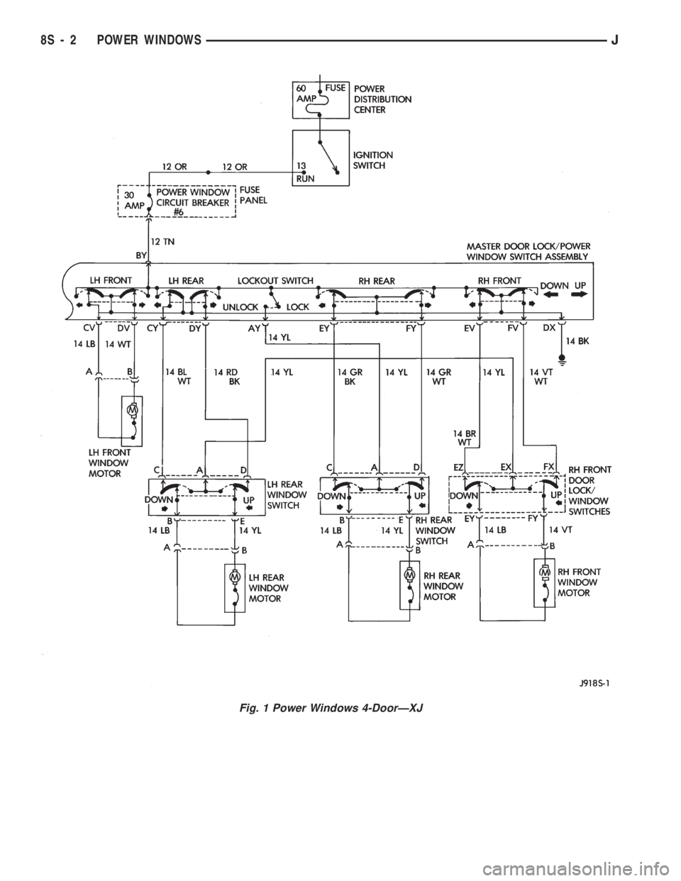
Fig. 1 Power Windows 4-DoorÐXJ
8S - 2 POWER WINDOWSJ
Page 474 of 1784
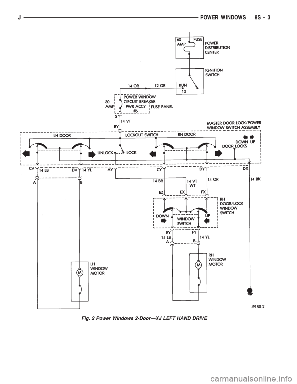
Fig. 2 Power Windows 2-DoorÐXJ LEFT HAND DRIVE
JPOWER WINDOWS 8S - 3
Page 475 of 1784
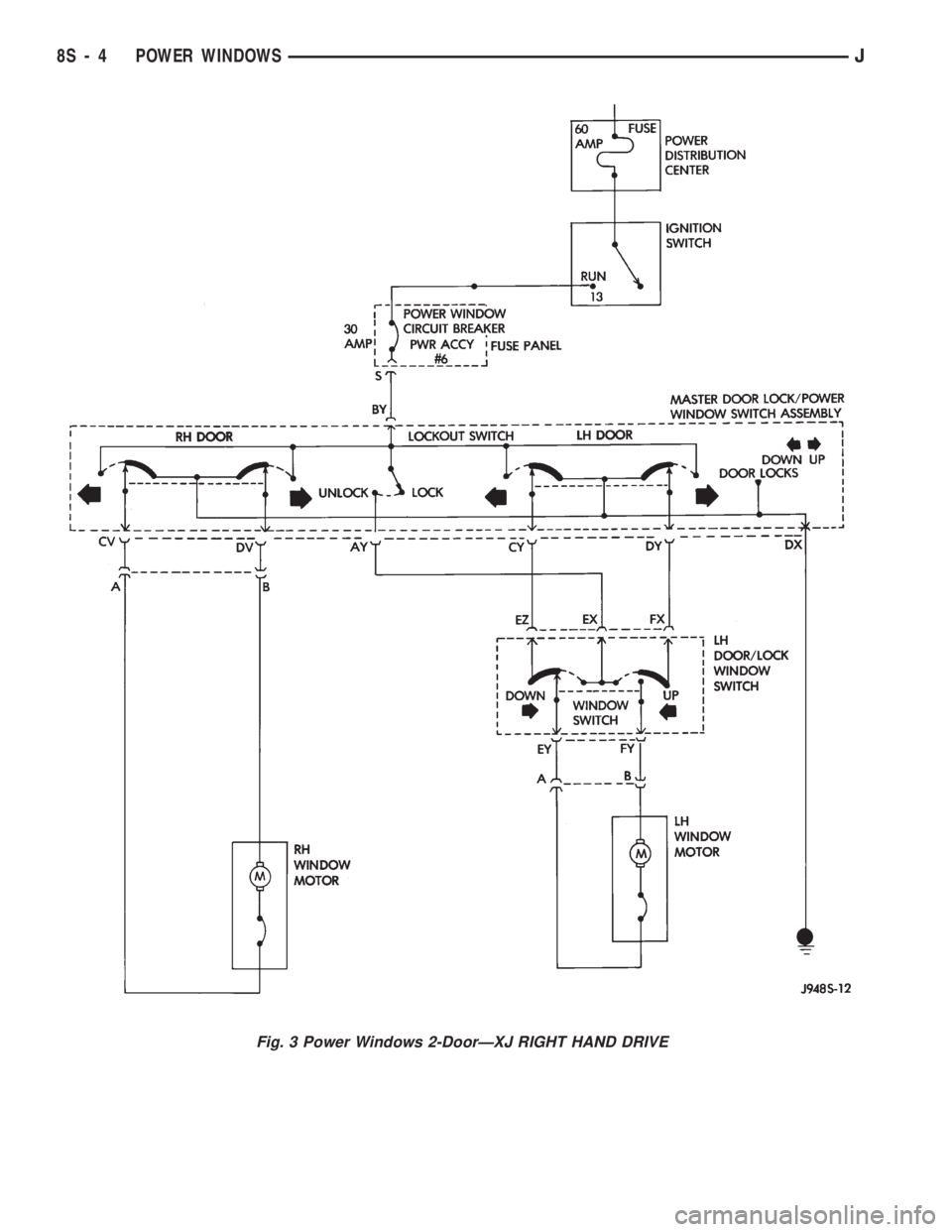
Fig. 3 Power Windows 2-DoorÐXJ RIGHT HAND DRIVE
8S - 4 POWER WINDOWSJ