1994 JEEP CHEROKEE service
[x] Cancel search: servicePage 932 of 1784
EXHAUST SYSTEM AND INTAKE MANIFOLD
CONTENTS
page page
EXHAUST SYSTEM....................... 1
EXHAUST SYSTEM DIAGNOSIS............ 2SERVICE PROCEDURES................... 3
TORQUE SPECIFICATIONS................ 10
EXHAUST SYSTEM
GENERAL INFORMATION
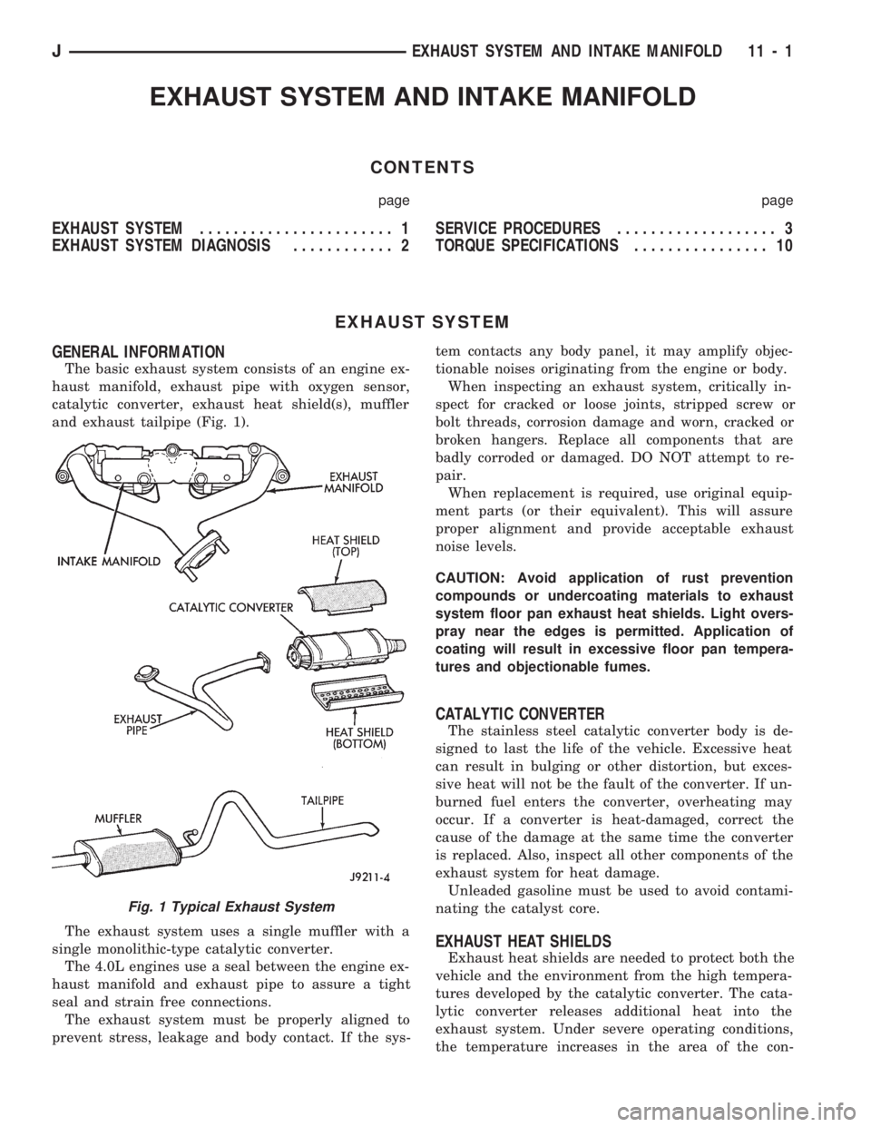
The basic exhaust system consists of an engine ex-
haust manifold, exhaust pipe with oxygen sensor,
catalytic converter, exhaust heat shield(s), muffler
and exhaust tailpipe (Fig. 1).
The exhaust system uses a single muffler with a
single monolithic-type catalytic converter.
The 4.0L engines use a seal between the engine ex-
haust manifold and exhaust pipe to assure a tight
seal and strain free connections.
The exhaust system must be properly aligned to
prevent stress, leakage and body contact. If the sys-tem contacts any body panel, it may amplify objec-
tionable noises originating from the engine or body.
When inspecting an exhaust system, critically in-
spect for cracked or loose joints, stripped screw or
bolt threads, corrosion damage and worn, cracked or
broken hangers. Replace all components that are
badly corroded or damaged. DO NOT attempt to re-
pair.
When replacement is required, use original equip-
ment parts (or their equivalent). This will assure
proper alignment and provide acceptable exhaust
noise levels.
CAUTION: Avoid application of rust prevention
compounds or undercoating materials to exhaust
system floor pan exhaust heat shields. Light overs-
pray near the edges is permitted. Application of
coating will result in excessive floor pan tempera-
tures and objectionable fumes.
CATALYTIC CONVERTER
The stainless steel catalytic converter body is de-
signed to last the life of the vehicle. Excessive heat
can result in bulging or other distortion, but exces-
sive heat will not be the fault of the converter. If un-
burned fuel enters the converter, overheating may
occur. If a converter is heat-damaged, correct the
cause of the damage at the same time the converter
is replaced. Also, inspect all other components of the
exhaust system for heat damage.
Unleaded gasoline must be used to avoid contami-
nating the catalyst core.
EXHAUST HEAT SHIELDS
Exhaust heat shields are needed to protect both the
vehicle and the environment from the high tempera-
tures developed by the catalytic converter. The cata-
lytic converter releases additional heat into the
exhaust system. Under severe operating conditions,
the temperature increases in the area of the con-
Fig. 1 Typical Exhaust System
JEXHAUST SYSTEM AND INTAKE MANIFOLD 11 - 1
Page 934 of 1784
SERVICE PROCEDURES
INDEX
page page
Catalytic Converter........................ 5
Engine Exhaust ManifoldÐ2.5L Engine......... 7
Engine Exhaust ManifoldÐ4.0L Engine......... 7
Exhaust PipeÐXJ Vehicles.................. 3
Exhaust PipeÐYJ Vehicles.................. 4Intake ManifoldÐ2.5L Engine................ 8
Intake ManifoldÐ4.0L Engine................ 9
Muffler and Exhaust TailpipeÐXJ Vehicles...... 5
Muffler and Exhaust TailpipeÐYJ Vehicles...... 6
EXHAUST PIPEÐXJ VEHICLES
WARNING: IF TORCHES ARE USED WHEN WORK-
ING ON THE EXHAUST SYSTEM, DO NOT ALLOW
THE FLAME NEAR THE FUEL LINES.
REMOVAL
(1) Raise and support the vehicle.
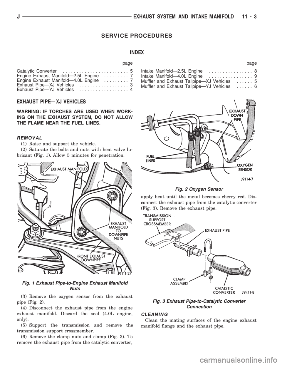
(2) Saturate the bolts and nuts with heat valve lu-
bricant (Fig. 1). Allow 5 minutes for penetration.
(3) Remove the oxygen sensor from the exhaust
pipe (Fig. 2).
(4) Disconnect the exhaust pipe from the engine
exhaust manifold. Discard the seal (4.0L engine,
only).
(5) Support the transmission and remove the
transmission support crossmember.
(6) Remove the clamp nuts and clamp (Fig. 3). To
remove the exhaust pipe from the catalytic converter,apply heat until the metal becomes cherry red. Dis-
connect the exhaust pipe from the catalytic converter
(Fig. 3). Remove the exhaust pipe.
CLEANING
Clean the mating surfaces of the engine exhaust
manifold flange and the exhaust pipe.
Fig. 1 Exhaust Pipe-to-Engine Exhaust Manifold
Nuts
Fig. 2 Oxygen Sensor
Fig. 3 Exhaust Pipe-to-Catalytic Converter
Connection
JEXHAUST SYSTEM AND INTAKE MANIFOLD 11 - 3
Page 936 of 1784
CATALYTIC CONVERTER
WARNING: IF TORCHES ARE USED WHEN WORK-
ING ON THE EXHAUST SYSTEM, DO NOT ALLOW
THE FLAME NEAR THE FUEL LINES.
REMOVAL
(1) Raise and support the vehicle.
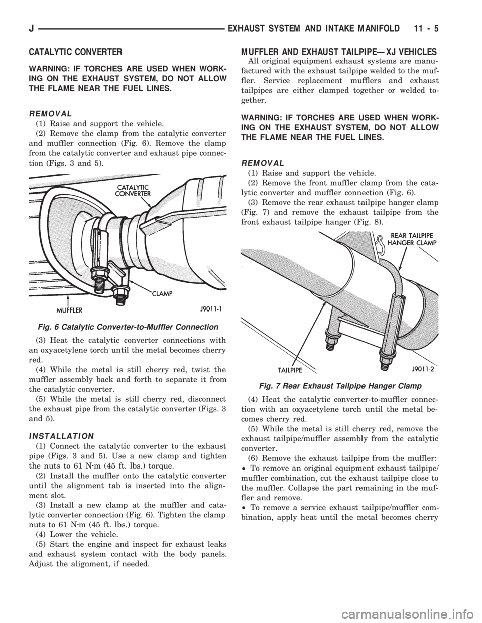
(2) Remove the clamp from the catalytic converter
and muffler connection (Fig. 6). Remove the clamp
from the catalytic converter and exhaust pipe connec-
tion (Figs. 3 and 5).
(3) Heat the catalytic converter connections with
an oxyacetylene torch until the metal becomes cherry
red.
(4) While the metal is still cherry red, twist the
muffler assembly back and forth to separate it from
the catalytic converter.
(5) While the metal is still cherry red, disconnect
the exhaust pipe from the catalytic converter (Figs. 3
and 5).
INSTALLATION
(1) Connect the catalytic converter to the exhaust
pipe (Figs. 3 and 5). Use a new clamp and tighten
the nuts to 61 Nzm (45 ft. lbs.) torque.
(2) Install the muffler onto the catalytic converter
until the alignment tab is inserted into the align-
ment slot.
(3) Install a new clamp at the muffler and cata-
lytic converter connection (Fig. 6). Tighten the clamp
nuts to 61 Nzm (45 ft. lbs.) torque.
(4) Lower the vehicle.
(5) Start the engine and inspect for exhaust leaks
and exhaust system contact with the body panels.
Adjust the alignment, if needed.
MUFFLER AND EXHAUST TAILPIPEÐXJ VEHICLES
All original equipment exhaust systems are manu-
factured with the exhaust tailpipe welded to the muf-
fler. Service replacement mufflers and exhaust
tailpipes are either clamped together or welded to-
gether.
WARNING: IF TORCHES ARE USED WHEN WORK-
ING ON THE EXHAUST SYSTEM, DO NOT ALLOW
THE FLAME NEAR THE FUEL LINES.
REMOVAL
(1) Raise and support the vehicle.
(2) Remove the front muffler clamp from the cata-
lytic converter and muffler connection (Fig. 6).
(3) Remove the rear exhaust tailpipe hanger clamp
(Fig. 7) and remove the exhaust tailpipe from the
front exhaust tailpipe hanger (Fig. 8).
(4) Heat the catalytic converter-to-muffler connec-
tion with an oxyacetylene torch until the metal be-
comes cherry red.
(5) While the metal is still cherry red, remove the
exhaust tailpipe/muffler assembly from the catalytic
converter.
(6) Remove the exhaust tailpipe from the muffler:
²To remove an original equipment exhaust tailpipe/
muffler combination, cut the exhaust tailpipe close to
the muffler. Collapse the part remaining in the muf-
fler and remove.
²To remove a service exhaust tailpipe/muffler com-
bination, apply heat until the metal becomes cherry
Fig. 6 Catalytic Converter-to-Muffler Connection
Fig. 7 Rear Exhaust Tailpipe Hanger Clamp
JEXHAUST SYSTEM AND INTAKE MANIFOLD 11 - 5
Page 937 of 1784
red. Remove the exhaust tailpipe/muffler clamp and
twist the exhaust tailpipe out of the muffler.
INSTALLATION
(1) Install the muffler onto the catalytic converter.
Install the clamp and tighten the nuts finger tight.
(2) Install the exhaust tailpipe into the rear of the
muffler.
(3) Install the exhaust tailpipe/muffler assembly
on the rear exhaust tailpipe hanger. Make sure that
the exhaust tailpipe has sufficient clearance from the
floor pan.
(4) Install the remaining clamps and the front ex-
haust tailpipe hanger.
(5) Tighten the nuts on the muffler-to-catalytic
converter clamp to 61 Nzm (45 ft. lbs.) torque (Fig.
6). Tighten the nuts on the rear exhaust tailpipe
clamp to 14 Nzm (10 ft. lbs.) torque (Fig. 7).
(6) Lower the vehicle.
(7) Start the engine and inspect for exhaust leaks
and exhaust system contact with the body panels.
Adjust the alignment, if needed.
MUFFLER AND EXHAUST TAILPIPEÐYJ VEHICLES
All original equipment exhaust systems are manu-
factured with the exhaust tailpipe welded to the muf-
fler. Service replacement mufflers and exhaust
tailpipes are clamped together.
WARNING: IF TORCHES ARE USED WHEN WORK-
ING ON THE EXHAUST SYSTEM, DO NOT ALLOW
THE FLAME NEAR THE FUEL LINES.
REMOVAL
(1) Raise the vehicle and support the rear of the
vehicle by the side rails and allow the axle to hang
free.
(2) Remove the front muffler clamp from the cata-
lytic converter and muffler connection (Fig. 6).
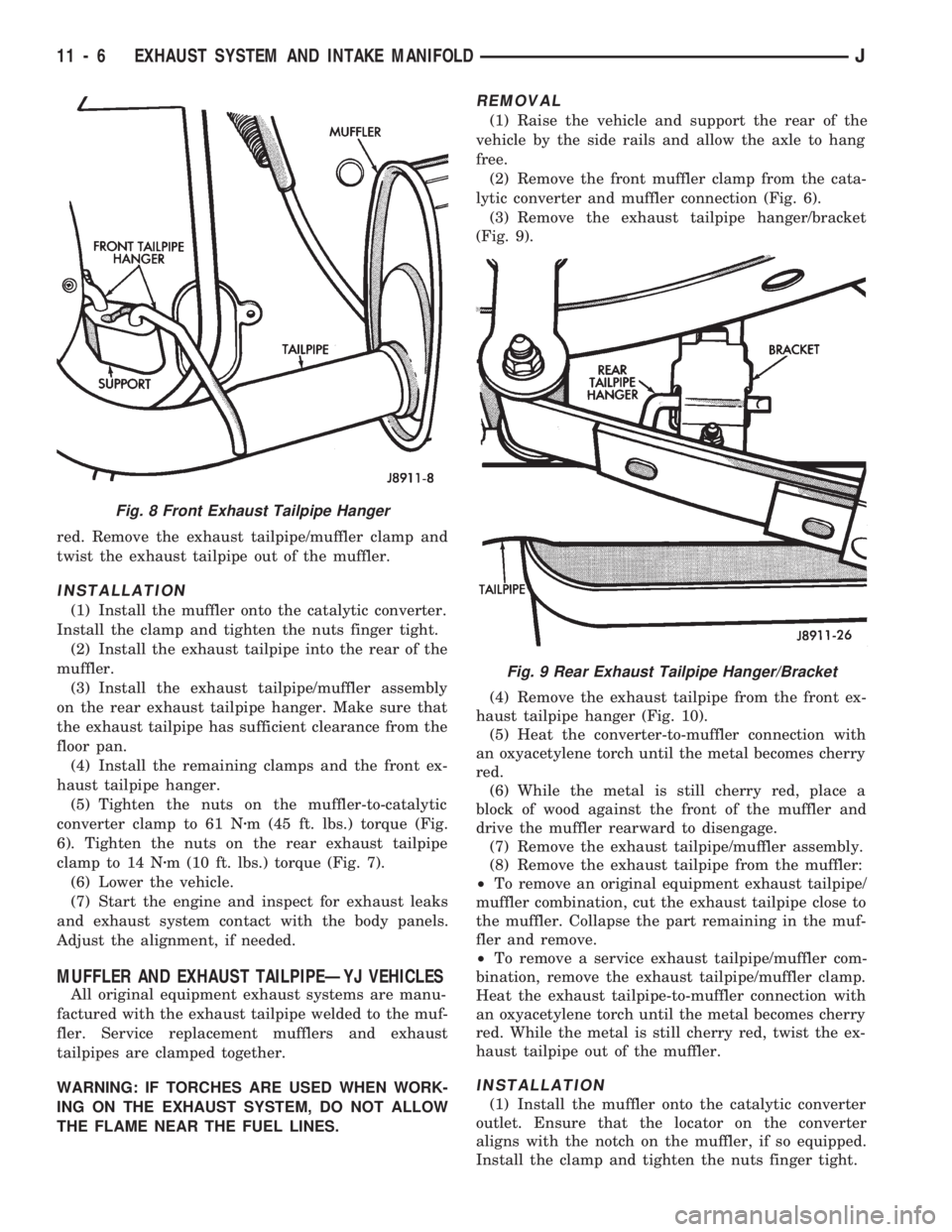
(3) Remove the exhaust tailpipe hanger/bracket
(Fig. 9).
(4) Remove the exhaust tailpipe from the front ex-
haust tailpipe hanger (Fig. 10).
(5) Heat the converter-to-muffler connection with
an oxyacetylene torch until the metal becomes cherry
red.
(6) While the metal is still cherry red, place a
block of wood against the front of the muffler and
drive the muffler rearward to disengage.
(7) Remove the exhaust tailpipe/muffler assembly.
(8) Remove the exhaust tailpipe from the muffler:
²To remove an original equipment exhaust tailpipe/
muffler combination, cut the exhaust tailpipe close to
the muffler. Collapse the part remaining in the muf-
fler and remove.
²To remove a service exhaust tailpipe/muffler com-
bination, remove the exhaust tailpipe/muffler clamp.
Heat the exhaust tailpipe-to-muffler connection with
an oxyacetylene torch until the metal becomes cherry
red. While the metal is still cherry red, twist the ex-
haust tailpipe out of the muffler.
INSTALLATION
(1) Install the muffler onto the catalytic converter
outlet. Ensure that the locator on the converter
aligns with the notch on the muffler, if so equipped.
Install the clamp and tighten the nuts finger tight.
Fig. 8 Front Exhaust Tailpipe Hanger
Fig. 9 Rear Exhaust Tailpipe Hanger/Bracket
11 - 6 EXHAUST SYSTEM AND INTAKE MANIFOLDJ
Page 944 of 1784
XJ BUMPERS
INDEX
page page
Front Bumper............................ 3
Front Tow Hooks......................... 5Rear Bumper............................ 6
FRONT BUMPER
REMOVAL/DISASSEMBLY
(1) The bumper guards, end caps and tow hooks
can be removed from XJ front bumpers with the
bumper attached to the vehicle. Do not remove the
bumper from the vehicle if only these components re-
quire service.
If equipped with a brush guard, refer to the
Brush Guard Removal within Group 23ÐBody
Components.
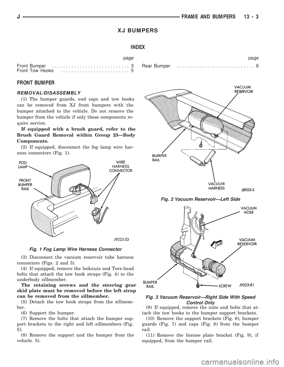
(2) If equipped, disconnect the fog lamp wire har-
ness connectors (Fig. 1).
(3) Disconnect the vacuum reservoir tube harness
connectors (Figs. 2 and 3).
(4) If equipped, remove the locknuts and Torx-head
bolts that attach the tow hook straps (Fig. 4) to the
underbody sillmember.
The retaining screws and the steering gear
skid plate must be removed before the left strap
can be removed from the sillmember.
(5) Detach the tow hook straps from the sillmem-
ber.
(6) Support the bumper.
(7) Remove the bolts that attach the bumper sup-
port brackets to the right and left sillmembers (Fig.
5).
(8) Remove the support and the bumper from the
vehicle. 5).(9) If equipped, remove the nuts and bolts that at-
tach the tow hooks to the bumper support brackets.
(10) Remove the support brackets (Fig. 6), bumper
guards (Fig. 7) and caps (Fig. 8) from the bumper
rail.
(11) Remove the license plate bracket (Fig. 9), if
equipped, from the bumper rail.
Fig. 1 Fog Lamp Wire Harness Connector
Fig. 2 Vacuum ReservoirÐLeft Side
Fig. 3 Vacuum ReservoirÐRight Side With Speed
Control Only
JFRAME AND BUMPERS 13 - 3
Page 946 of 1784
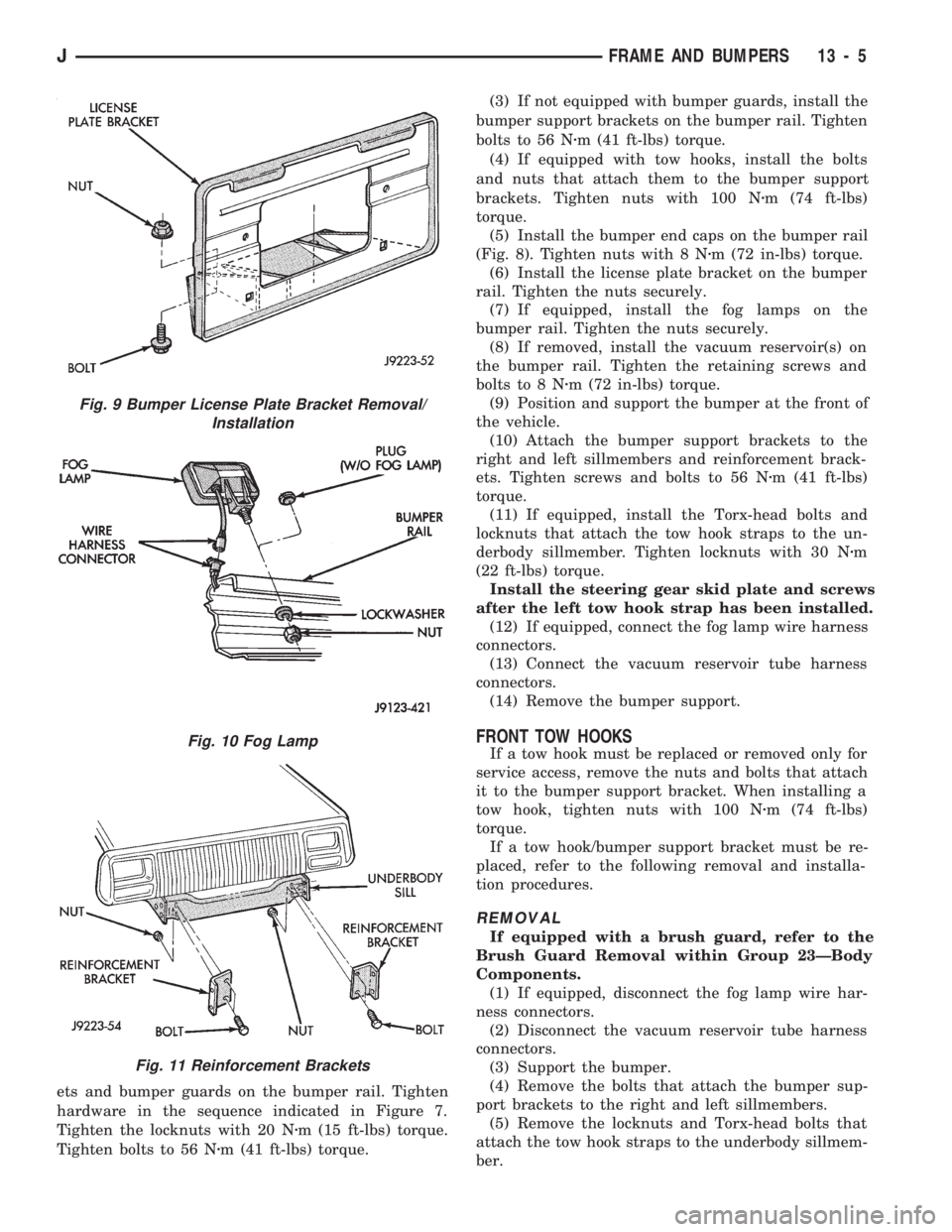
ets and bumper guards on the bumper rail. Tighten
hardware in the sequence indicated in Figure 7.
Tighten the locknuts with 20 Nzm (15 ft-lbs) torque.
Tighten bolts to 56 Nzm (41 ft-lbs) torque.(3) If not equipped with bumper guards, install the
bumper support brackets on the bumper rail. Tighten
bolts to 56 Nzm (41 ft-lbs) torque.
(4) If equipped with tow hooks, install the bolts
and nuts that attach them to the bumper support
brackets. Tighten nuts with 100 Nzm (74 ft-lbs)
torque.
(5) Install the bumper end caps on the bumper rail
(Fig. 8). Tighten nuts with 8 Nzm (72 in-lbs) torque.
(6) Install the license plate bracket on the bumper
rail. Tighten the nuts securely.
(7) If equipped, install the fog lamps on the
bumper rail. Tighten the nuts securely.
(8) If removed, install the vacuum reservoir(s) on
the bumper rail. Tighten the retaining screws and
bolts to 8 Nzm (72 in-lbs) torque.
(9) Position and support the bumper at the front of
the vehicle.
(10) Attach the bumper support brackets to the
right and left sillmembers and reinforcement brack-
ets. Tighten screws and bolts to 56 Nzm (41 ft-lbs)
torque.
(11) If equipped, install the Torx-head bolts and
locknuts that attach the tow hook straps to the un-
derbody sillmember. Tighten locknuts with 30 Nzm
(22 ft-lbs) torque.
Install the steering gear skid plate and screws
after the left tow hook strap has been installed.
(12) If equipped, connect the fog lamp wire harness
connectors.
(13) Connect the vacuum reservoir tube harness
connectors.
(14) Remove the bumper support.
FRONT TOW HOOKS
If a tow hook must be replaced or removed only for
service access, remove the nuts and bolts that attach
it to the bumper support bracket. When installing a
tow hook, tighten nuts with 100 Nzm (74 ft-lbs)
torque.
If a tow hook/bumper support bracket must be re-
placed, refer to the following removal and installa-
tion procedures.
REMOVAL
If equipped with a brush guard, refer to the
Brush Guard Removal within Group 23ÐBody
Components.
(1) If equipped, disconnect the fog lamp wire har-
ness connectors.
(2) Disconnect the vacuum reservoir tube harness
connectors.
(3) Support the bumper.
(4) Remove the bolts that attach the bumper sup-
port brackets to the right and left sillmembers.
(5) Remove the locknuts and Torx-head bolts that
attach the tow hook straps to the underbody sillmem-
ber.
Fig. 9 Bumper License Plate Bracket Removal/
Installation
Fig. 10 Fog Lamp
Fig. 11 Reinforcement Brackets
JFRAME AND BUMPERS 13 - 5
Page 949 of 1784
YJ FRAME
INDEX
page page
Frame Alignment......................... 10
Frame Inspection/Measurements............. 10Frame Repair Service..................... 13
General Information........................ 8
GENERAL INFORMATION
FUNCTIONS
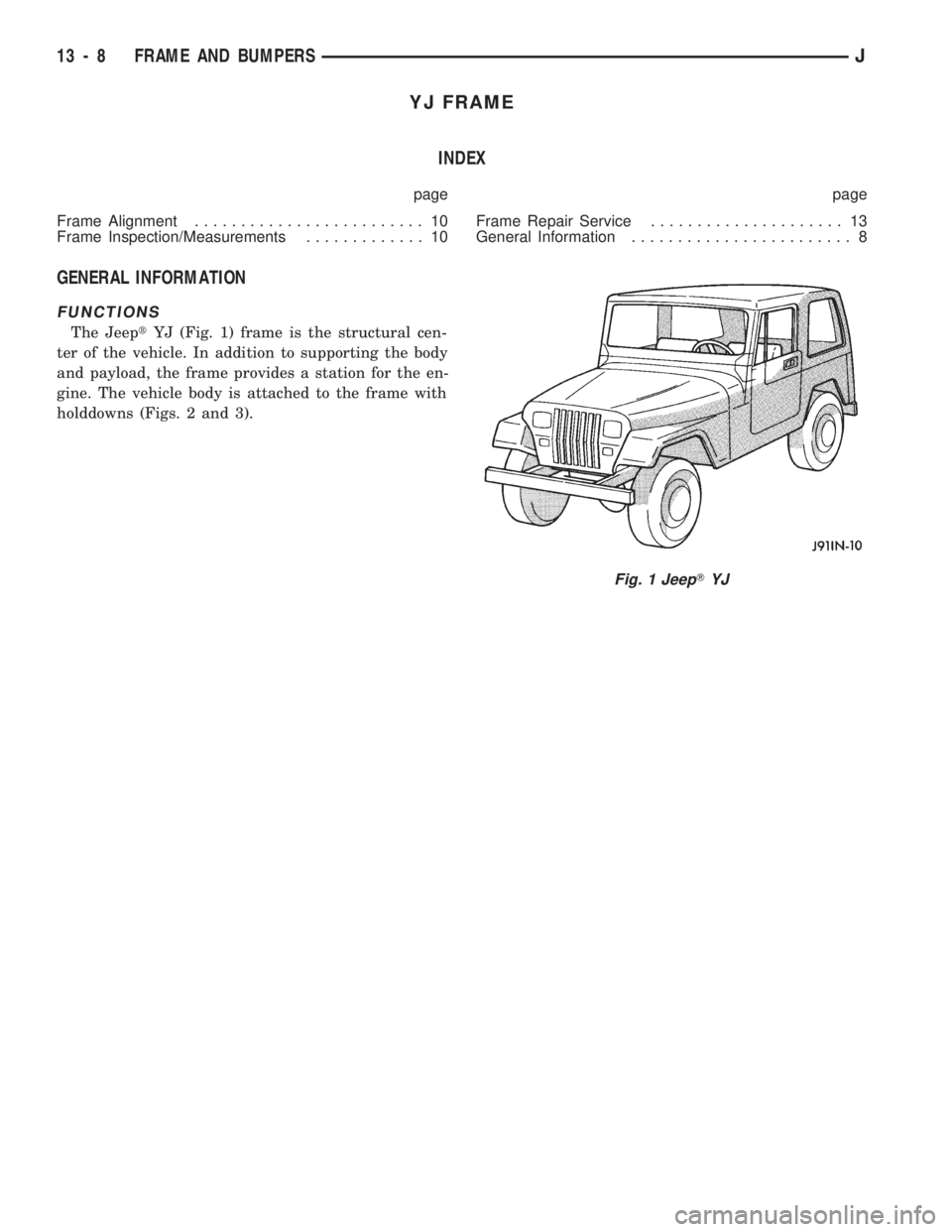
The JeeptYJ (Fig. 1) frame is the structural cen-
ter of the vehicle. In addition to supporting the body
and payload, the frame provides a station for the en-
gine. The vehicle body is attached to the frame with
holddowns (Figs. 2 and 3).
Fig. 1 JeepTYJ
13 - 8 FRAME AND BUMPERSJ
Page 954 of 1784
FRAME REPAIR SERVICE
When necessary, conventional vehicle frames that
are bent or twisted can be straightened by applica-
tion of heat. The temperature must not exceed 566ÉC/
1050ÉF.
Damaged frame siderails, crossmembers, and
brackets are repaired either by straightening or by
replacement.
Welded joints between the frame siderails and
crossmembers are not recommended.
FRAME STRAIGHTENING
A straightening repair process should be limited to
frame components that are not severely damaged.
The bolts, nuts and rivets should conform to the spec-
ifications as the original.
FRAME COMPONENT REPLACEMENT
An improperly straightened frame component will
have harmful effects on the overall frame alignment.
FRAME COMPONENT REPAIRS
DRILLING HOLES
Holesshould notbe drilled in frame siderail
flanges because this will severely reduce the frame
strength. Holes drilled in the frame siderail vertical
webs must be 38 mm (1 and 1/2 in) minimum from
the top and bottom flanges.
Newly drilled holes should be located an acceptable
distance away from any existing holes.WELDING
It is recommended that electric welding equipment
be used to weld frame siderails and crossmembers.
A damaged frame component should be closely ex-
amined for hairline cracks. Repair frame component
cracks according to the following procedure.
(1) Drill a hole at each end of the crack with a
3-mm (1/8-in) diameter drill bit.
(2) ``V-groove'' the crack to allow good weld pene-
tration.
(3) Weld the crack.
(4) Grind the weld surface area smooth and install
a reinforcement section at the welded area.
The flanges on reinforcement channel should
be less in width than the siderail flanges. Other-
wise, longitudinal welds are very acceptable.
Complete transverse welds should be avoided.
FRAME REPAIR HARDWARE
Bolts, nuts and rivets can be used to repair frames
or to install a reinforcement section on the frame.
When it is more practical to substitute a bolt for a
rivet, install the next-larger-size diameter bolt to
prevent the bolt from loosening.
Conical-type lockwashers are preferred over the
split-ring type lockwashers. Normally, grade-5 bolts
are adequate for frame repair.Grade-3 bolts (or
less) should not be used.Tightening bolts/nuts
with the correct torque is mandatory to adequately
``lock'' the bolt, lockwasher and nut together, and to
prevent them from loosening.
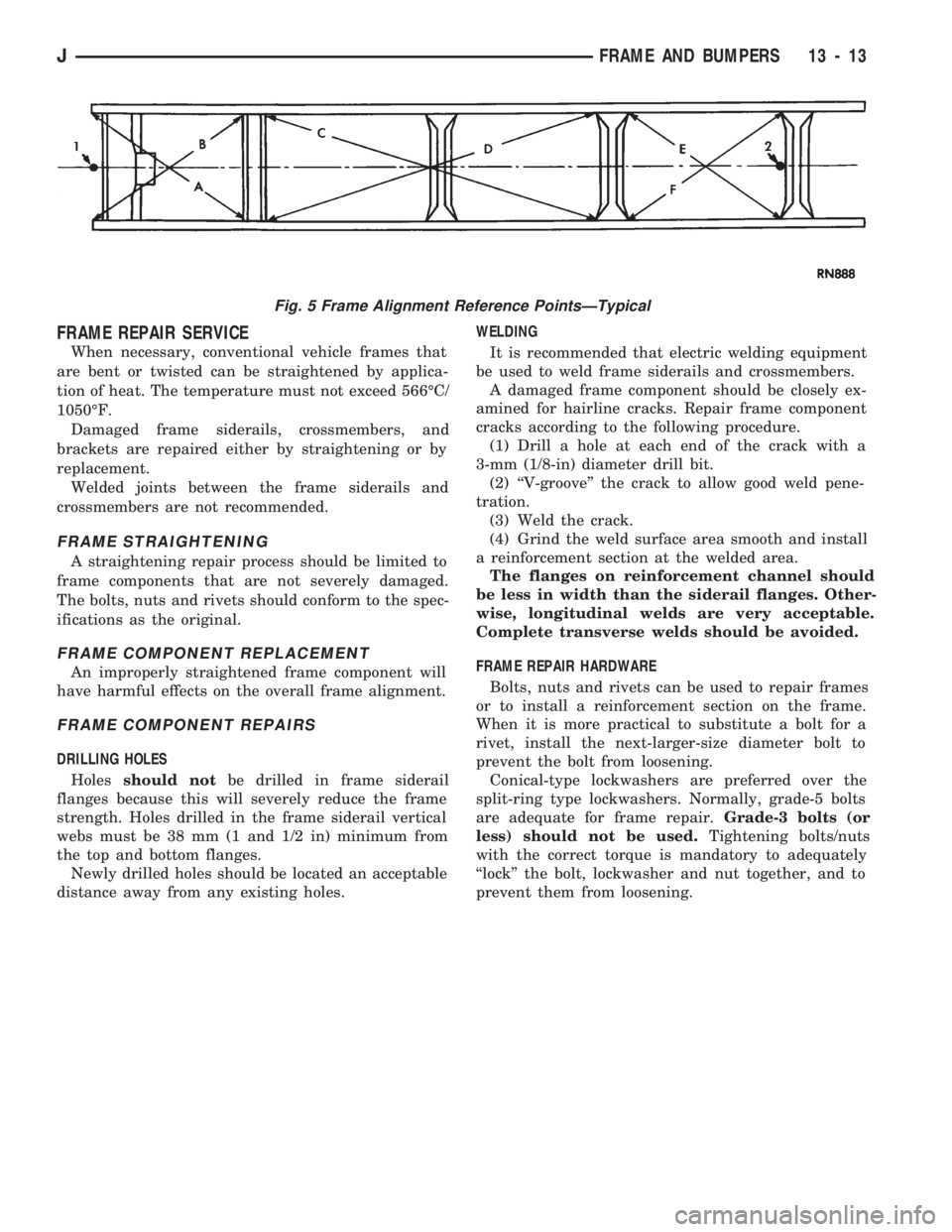
Fig. 5 Frame Alignment Reference PointsÐTypical
JFRAME AND BUMPERS 13 - 13