1994 JEEP CHEROKEE service
[x] Cancel search: servicePage 1056 of 1784
INSTALLATION
(1) Align and install the pitman arm on steering
gear shaft.
(2) Install the washer and nut on the shaft.
Tighten the nut to 251 Nzm (185 ft. lbs.) torque.
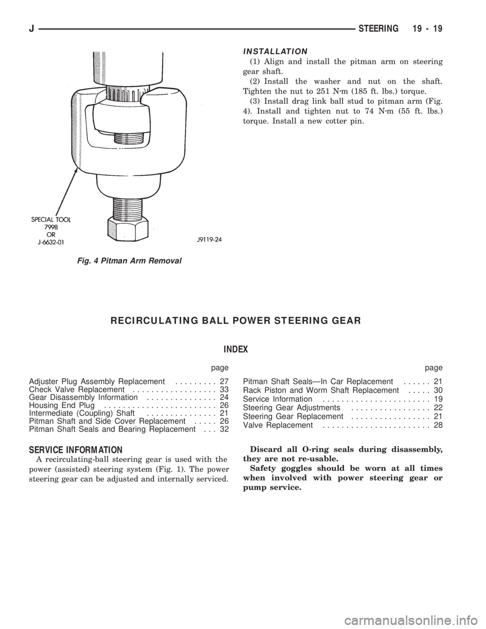
(3) Install drag link ball stud to pitman arm (Fig.
4). Install and tighten nut to 74 Nzm (55 ft. lbs.)
torque. Install a new cotter pin.
RECIRCULATING BALL POWER STEERING GEAR
INDEX
page page
Adjuster Plug Assembly Replacement......... 27
Check Valve Replacement.................. 33
Gear Disassembly Information............... 24
Housing End Plug........................ 26
Intermediate (Coupling) Shaft............... 21
Pitman Shaft and Side Cover Replacement..... 26
Pitman Shaft Seals and Bearing Replacement . . . 32Pitman Shaft SealsÐIn Car Replacement...... 21
Rack Piston and Worm Shaft Replacement..... 30
Service Information....................... 19
Steering Gear Adjustments................. 22
Steering Gear Replacement................. 21
Valve Replacement....................... 28
SERVICE INFORMATION
A recirculating-ball steering gear is used with the
power (assisted) steering system (Fig. 1). The power
steering gear can be adjusted and internally serviced.Discard all O-ring seals during disassembly,
they are not re-usable.
Safety goggles should be worn at all times
when involved with power steering gear or
pump service.
Fig. 4 Pitman Arm Removal
JSTEERING 19 - 19
Page 1059 of 1784
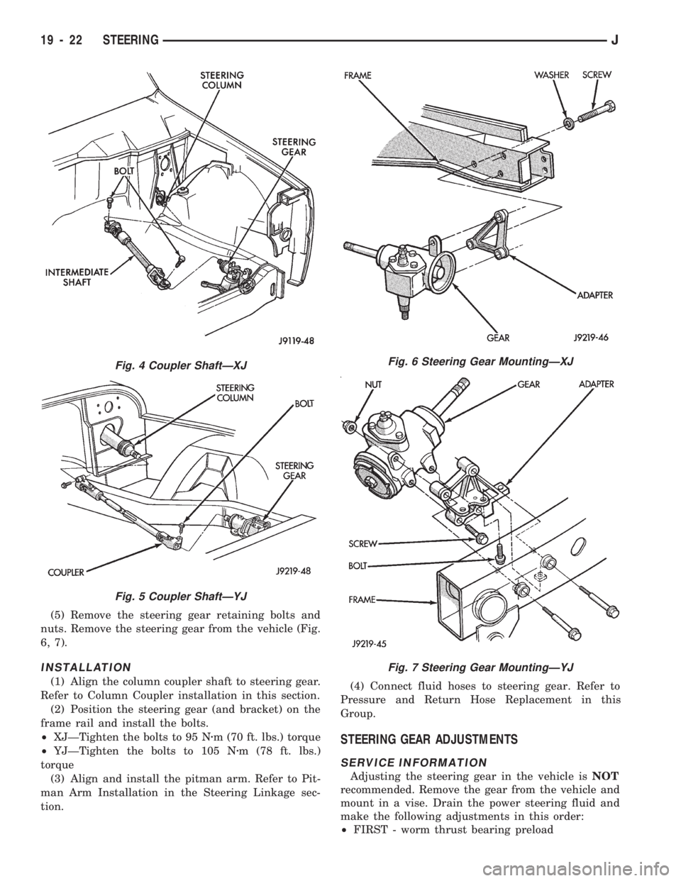
(5) Remove the steering gear retaining bolts and
nuts. Remove the steering gear from the vehicle (Fig.
6, 7).
INSTALLATION
(1) Align the column coupler shaft to steering gear.
Refer to Column Coupler installation in this section.
(2) Position the steering gear (and bracket) on the
frame rail and install the bolts.
²XJÐTighten the bolts to 95 Nzm (70 ft. lbs.) torque
²YJÐTighten the bolts to 105 Nzm (78 ft. lbs.)
torque
(3) Align and install the pitman arm. Refer to Pit-
man Arm Installation in the Steering Linkage sec-
tion.(4) Connect fluid hoses to steering gear. Refer to
Pressure and Return Hose Replacement in this
Group.
STEERING GEAR ADJUSTMENTS
SERVICE INFORMATION
Adjusting the steering gear in the vehicle isNOT
recommended. Remove the gear from the vehicle and
mount in a vise. Drain the power steering fluid and
make the following adjustments in this order:
²FIRST - worm thrust bearing preload
Fig. 6 Steering Gear MountingÐXJ
Fig. 7 Steering Gear MountingÐYJ
Fig. 4 Coupler ShaftÐXJ
Fig. 5 Coupler ShaftÐYJ
19 - 22 STEERINGJ
Page 1082 of 1784
STEERING COLUMN GENERAL SERVICE
INDEX
page page
Column ReplacementÐXJ.................. 46
Column ReplacementÐYJ.................. 48
Park-Lock CableÐConsole Shift Automatic..... 45Service Information....................... 45
Steering Wheel.......................... 45
SERVICE INFORMATION
The column may be disassembled and reassembled.
Also most steering column components can be ser-
viced without removing the column from the vehicle.
For additional information, refer to Group 8H, Elec-
trical.
CAUTION: Bumping, jolting and hammering on the
steering column shaft and gear shift tube must be
avoided during all service procedures.
CAUTION: Disconnect negative (ground) cable from
the battery before servicing any component on the
column.
Safety goggles should be worn at all times
when involved with steering column service.
STEERING WHEEL
REMOVAL
(1) Make sure the front wheels are in thestraight
aheadposition.
(2) Disconnect the negative (ground) cable from the
battery.
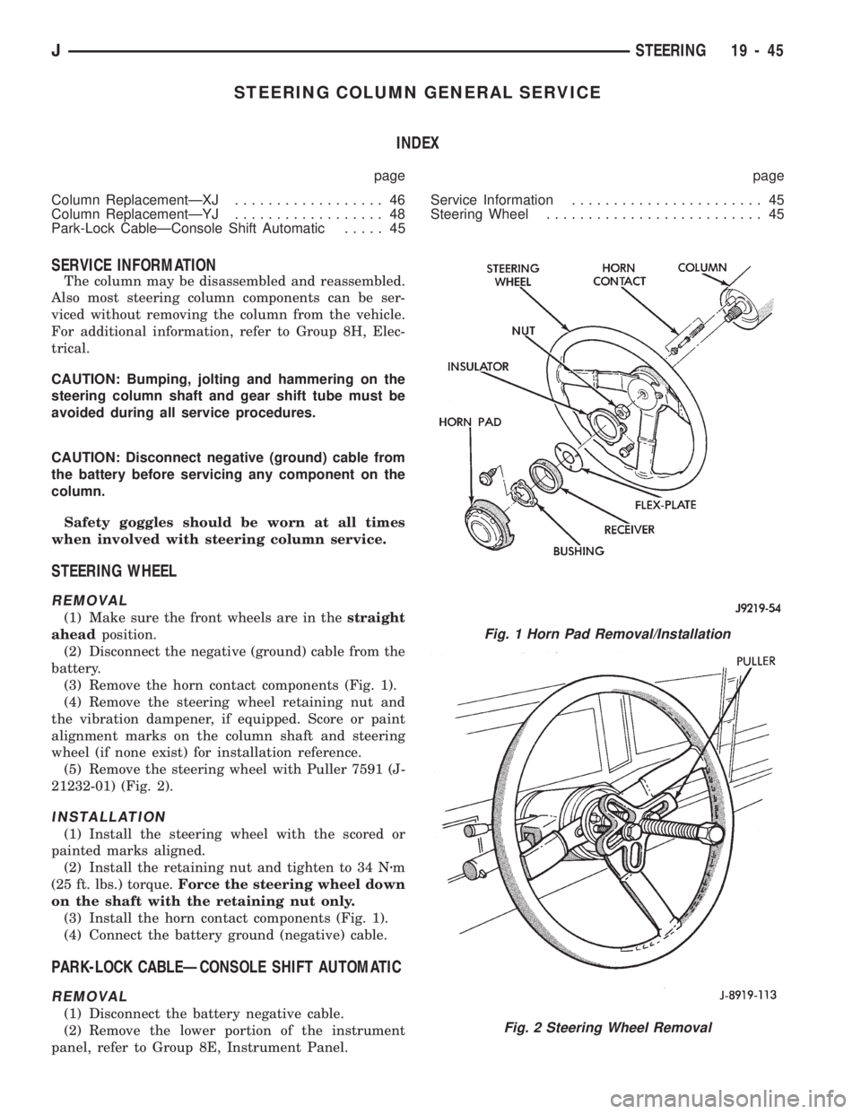
(3) Remove the horn contact components (Fig. 1).
(4) Remove the steering wheel retaining nut and
the vibration dampener, if equipped. Score or paint
alignment marks on the column shaft and steering
wheel (if none exist) for installation reference.
(5) Remove the steering wheel with Puller 7591 (J-
21232-01) (Fig. 2).
INSTALLATION
(1) Install the steering wheel with the scored or
painted marks aligned.
(2) Install the retaining nut and tighten to 34 Nzm
(25 ft. lbs.) torque.Force the steering wheel down
on the shaft with the retaining nut only.
(3) Install the horn contact components (Fig. 1).
(4) Connect the battery ground (negative) cable.
PARK-LOCK CABLEÐCONSOLE SHIFT AUTOMATIC
REMOVAL
(1) Disconnect the battery negative cable.
(2) Remove the lower portion of the instrument
panel, refer to Group 8E, Instrument Panel.
Fig. 1 Horn Pad Removal/Installation
Fig. 2 Steering Wheel Removal
JSTEERING 19 - 45
Page 1083 of 1784
(3) Remove the steering column mounting bracket
to instrument panel nuts. Lower the steering column.
Refer to Steering Column Removal .
(4) Disconnect the park-lock cable from the steer-
ing column and bracket.
(5) Remove the center console and related trim.
(6) Pull the carpet backward to expose the cable at
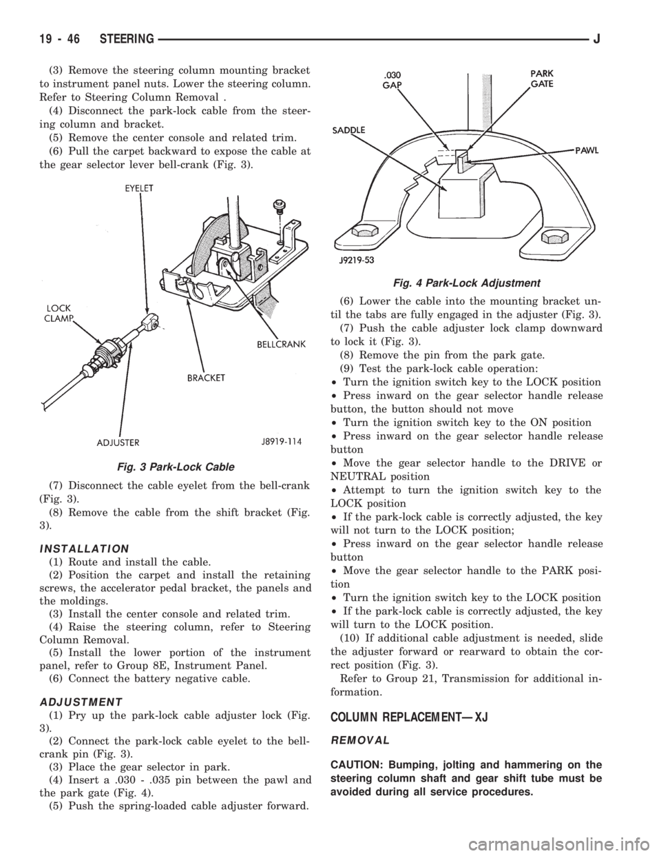
the gear selector lever bell-crank (Fig. 3).
(7) Disconnect the cable eyelet from the bell-crank
(Fig. 3).
(8) Remove the cable from the shift bracket (Fig.
3).
INSTALLATION
(1) Route and install the cable.
(2) Position the carpet and install the retaining
screws, the accelerator pedal bracket, the panels and
the moldings.
(3) Install the center console and related trim.
(4) Raise the steering column, refer to Steering
Column Removal.
(5) Install the lower portion of the instrument
panel, refer to Group 8E, Instrument Panel.
(6) Connect the battery negative cable.
ADJUSTMENT
(1) Pry up the park-lock cable adjuster lock (Fig.
3).
(2) Connect the park-lock cable eyelet to the bell-
crank pin (Fig. 3).
(3) Place the gear selector in park.
(4) Insert a .030 - .035 pin between the pawl and
the park gate (Fig. 4).
(5) Push the spring-loaded cable adjuster forward.(6) Lower the cable into the mounting bracket un-
til the tabs are fully engaged in the adjuster (Fig. 3).
(7) Push the cable adjuster lock clamp downward
to lock it (Fig. 3).
(8) Remove the pin from the park gate.
(9) Test the park-lock cable operation:
²Turn the ignition switch key to the LOCK position
²Press inward on the gear selector handle release
button, the button should not move
²Turn the ignition switch key to the ON position
²Press inward on the gear selector handle release
button
²Move the gear selector handle to the DRIVE or
NEUTRAL position
²Attempt to turn the ignition switch key to the
LOCK position
²If the park-lock cable is correctly adjusted, the key
will not turn to the LOCK position;
²Press inward on the gear selector handle release
button
²Move the gear selector handle to the PARK posi-
tion
²Turn the ignition switch key to the LOCK position
²If the park-lock cable is correctly adjusted, the key
will turn to the LOCK position.
(10) If additional cable adjustment is needed, slide
the adjuster forward or rearward to obtain the cor-
rect position (Fig. 3).
Refer to Group 21, Transmission for additional in-
formation.COLUMN REPLACEMENTÐXJ
REMOVAL
CAUTION: Bumping, jolting and hammering on the
steering column shaft and gear shift tube must be
avoided during all service procedures.
Fig. 3 Park-Lock Cable
Fig. 4 Park-Lock Adjustment
19 - 46 STEERINGJ
Page 1085 of 1784
(11) Disconnect the following items from the steer-
ing column connectors:
²Ignition switch wire harness
²Dimmer switch wire harness
²Turn signal switch wire harness
²Windshield wiper wire harness
²Cruise control wire harness (if equipped)
²Park-lock cable (if equipped)
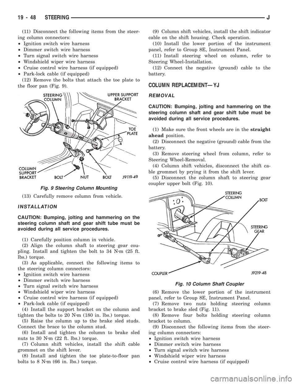
(12) Remove the bolts that attach the toe plate to
the floor pan (Fig. 9).
(13) Carefully remove column from vehicle.
INSTALLATION
CAUTION: Bumping, jolting and hammering on the
steering column shaft and gear shift tube must be
avoided during all service procedures.
(1) Carefully position column in vehicle.
(2) Align the column shaft to steering gear cou-
pling. Install and tighten the bolt to 34 Nzm (25 ft.
lbs.) torque.
(3) As applicable, connect the following items to
the steering column connectors:
²Ignition switch wire harness
²Dimmer switch wire harness
²Turn signal switch wire harness
²Windshield wiper wire harness
²Cruise control wire harness (if equipped)
²Park-lock cable (if equipped)
(4) Install the support bracket on the column and
tighten the bolts to 20 Nzm (180 in. lbs.) torque.
(5) Raise the column up to the brake sled studs.
Connect the brace to the column stud.
(6) Install and tighten the column to brake sled
nuts to 30 Nzm (22 ft. lbs.) torque.
(7) Column shift vehicles, install the shift cable
grommet on the shift lever.
(8) Install and tighten the toe plate-to-floor pan
bolts to 8 Nzm (66 in. lbs.) torque.(9) Column shift vehicles, install the shift indicator
cable on the shift housing. Check operation.
(10) Install the lower portion of the instrument
panel, refer to Group 8E, Instrument Panel.
(11) Install steering wheel on column, refer to
Steering Wheel-Installation.
(12) Connect the negative (ground) cable to the
battery.
COLUMN REPLACEMENTÐYJ
REMOVAL
CAUTION: Bumping, jolting and hammering on the
steering column shaft and gear shift tube must be
avoided during all service procedures.
(1) Make sure the front wheels are in thestraight
aheadposition.
(2) Disconnect the negative (ground) cable from the
battery.
(3) Remove steering wheel from column, refer to
Steering Wheel-Removal.
(4) Column shift vehicles, disconnect the shift ca-
ble grommet by prying it from the shift lever.
(5) Disconnect the column shaft to steering gear
coupler upper bolt (Fig. 10).
(6) Remove the lower portion of the instrument
panel, refer to Group 8E, Instrument Panel.
(7) Remove two nuts holding steering column
bracket to brake sled (Fig. 11).
(8) Remove four bolts holding steering column
bracket to column.
(9) Disconnect the following items from the steer-
ing column connectors:
²Ignition switch wire harness
²Dimmer switch wire harness
²Turn signal switch wire harness
²Windshield wiper wire harness
²Cruise control wire harness (if equipped)
Fig. 9 Steering Column Mounting
Fig. 10 Column Shaft Coupler
19 - 48 STEERINGJ
Page 1086 of 1784
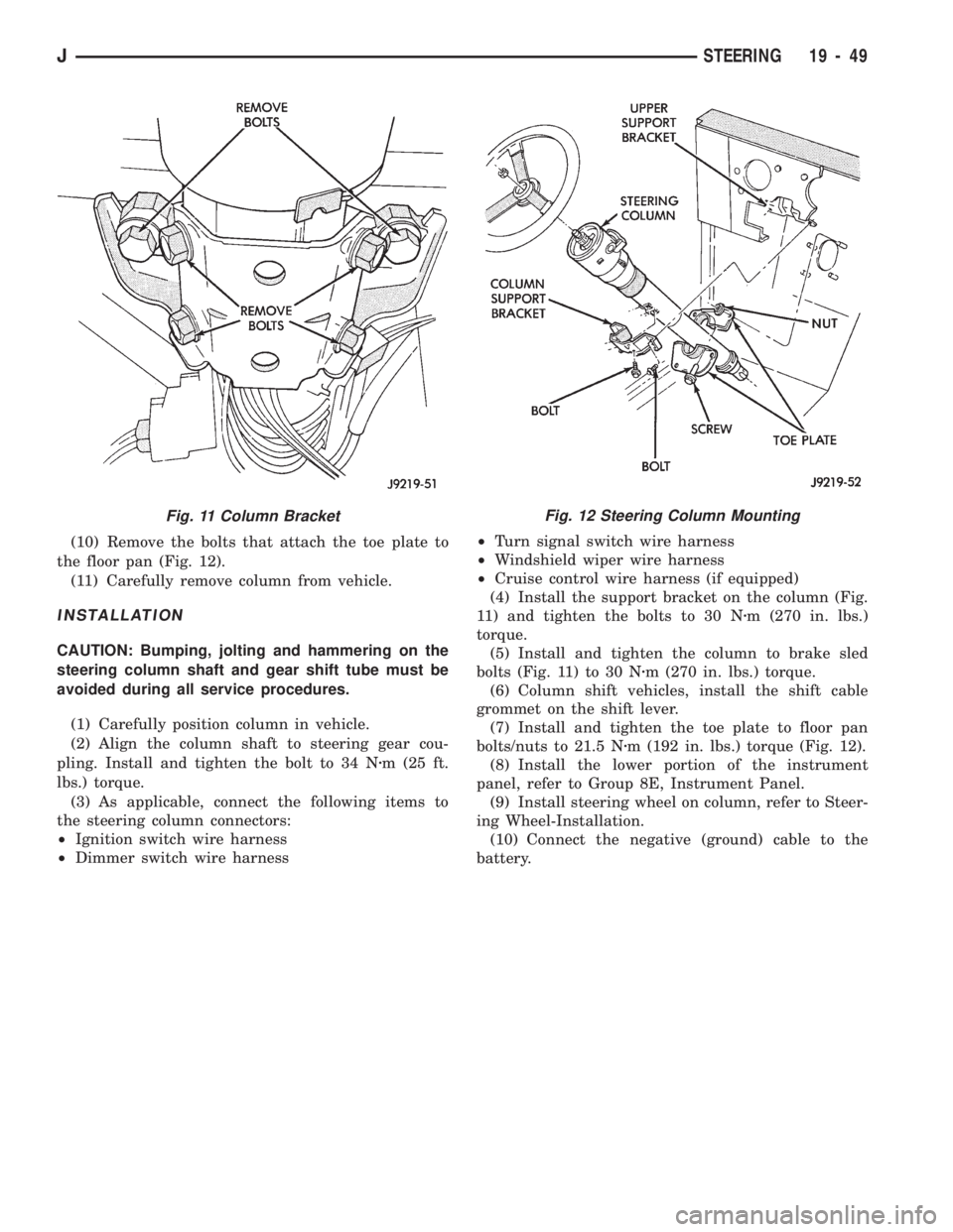
(10) Remove the bolts that attach the toe plate to
the floor pan (Fig. 12).
(11) Carefully remove column from vehicle.
INSTALLATION
CAUTION: Bumping, jolting and hammering on the
steering column shaft and gear shift tube must be
avoided during all service procedures.
(1) Carefully position column in vehicle.
(2) Align the column shaft to steering gear cou-
pling. Install and tighten the bolt to 34 Nzm (25 ft.
lbs.) torque.
(3) As applicable, connect the following items to
the steering column connectors:
²Ignition switch wire harness
²Dimmer switch wire harness²Turn signal switch wire harness
²Windshield wiper wire harness
²Cruise control wire harness (if equipped)
(4) Install the support bracket on the column (Fig.
11) and tighten the bolts to 30 Nzm (270 in. lbs.)
torque.
(5) Install and tighten the column to brake sled
bolts (Fig. 11) to 30 Nzm (270 in. lbs.) torque.
(6) Column shift vehicles, install the shift cable
grommet on the shift lever.
(7) Install and tighten the toe plate to floor pan
bolts/nuts to 21.5 Nzm (192 in. lbs.) torque (Fig. 12).
(8) Install the lower portion of the instrument
panel, refer to Group 8E, Instrument Panel.
(9) Install steering wheel on column, refer to Steer-
ing Wheel-Installation.
(10) Connect the negative (ground) cable to the
battery.
Fig. 11 Column BracketFig. 12 Steering Column Mounting
JSTEERING 19 - 49
Page 1087 of 1784
NON-TILT STEERING COLUMN
DISASSEMBLYÐCOLUMN OR CONSOLE SHIFT
Steering column removal from the vehicle is not
necessary for;
²Lockplate cover
²Lockplate
²Steering shaft retaining ring
²Canceling cam
²Turn signal switch
²Upper bearing preload spring
²Ignition key/lock cylinder service
The steering column must be removed from
the vehicle to service any other component.
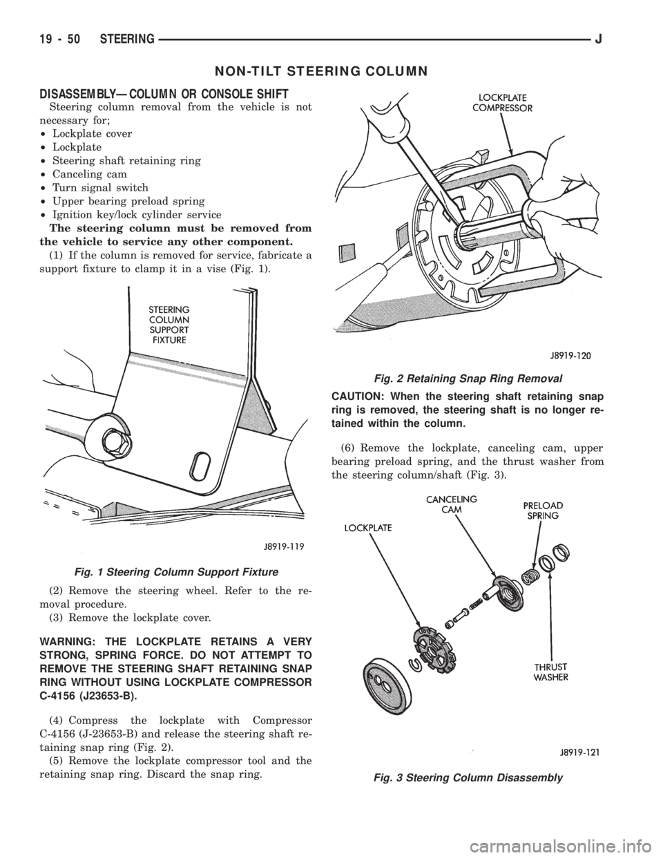
(1) If the column is removed for service, fabricate a
support fixture to clamp it in a vise (Fig. 1).
(2) Remove the steering wheel. Refer to the re-
moval procedure.
(3) Remove the lockplate cover.
WARNING: THE LOCKPLATE RETAINS A VERY
STRONG, SPRING FORCE. DO NOT ATTEMPT TO
REMOVE THE STEERING SHAFT RETAINING SNAP
RING WITHOUT USING LOCKPLATE COMPRESSOR
C-4156 (J23653-B).
(4) Compress the lockplate with Compressor
C-4156 (J-23653-B) and release the steering shaft re-
taining snap ring (Fig. 2).
(5) Remove the lockplate compressor tool and the
retaining snap ring. Discard the snap ring.CAUTION: When the steering shaft retaining snap
ring is removed, the steering shaft is no longer re-
tained within the column.
(6) Remove the lockplate, canceling cam, upper
bearing preload spring, and the thrust washer from
the steering column/shaft (Fig. 3).
Fig. 2 Retaining Snap Ring Removal
Fig. 3 Steering Column Disassembly
Fig. 1 Steering Column Support Fixture
19 - 50 STEERINGJ
Page 1096 of 1784
TILT STEERING COLUMN
DISASSEMBLY
(1) Remove the steering column from the vehicle,
if necessary. Refer to the removal procedure.
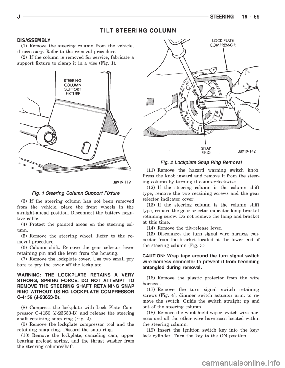
(2) If the column is removed for service, fabricate a
support fixture to clamp it in a vise (Fig. 1).
(3) If the steering column has not been removed
from the vehicle, place the front wheels in the
straight-ahead position. Disconnect the battery nega-
tive cable.
(4) Protect the painted areas on the steering col-
umn.
(5) Remove the steering wheel. Refer to the re-
moval procedure.
(6) Column shift: Remove the gear selector lever
retaining pin and the lever from the housing.
(7) Remove the lockplate cover. Use two small pry
bars to pry the cover off the lockplate.
WARNING: THE LOCKPLATE RETAINS A VERY
STRONG, SPRING FORCE. DO NOT ATTEMPT TO
REMOVE THE STEERING SHAFT RETAINING SNAP
RING WITHOUT USING LOCKPLATE COMPRESSOR
C-4156 (J-23653-B).
(8) Compress the lockplate with Lock Plate Com-
pressor C-4156 (J-23653-B) and release the steering
shaft retaining snap ring (Fig. 2).
(9) Remove the lockplate compressor tool and the
retaining snap ring. Discard the snap ring.
(10) Remove the lockplate, canceling cam, upper
bearing preload spring, and the thrust washer from
the steering column/shaft.(11) Remove the hazard warning switch knob.
Press the knob inward and remove it from the steer-
ing column by turning it counterclockwise.
(12) If the steering column is the column shift
type, remove the two retaining screws and the gear
selector indicator cover.
(13) If the steering column is the column shift
type, remove the gear selector indicator lamp bracket
retaining screw. Do not remove the lamp and bracket
at this time.
(14) Remove the tilt-release lever.
(15) Disconnect the turn signal wire harness con-
nector from the bracket located at the lower end of
the steering column (Fig. 3).
CAUTION: Wrap tape around the turn signal switch
wire harness connector to prevent it from becoming
entangled during removal.
(16) Remove the plastic protector from the wire
harness.
(17) Remove the turn signal switch retaining
screws (Fig. 4), dimmer switch actuator arm, to re-
move the switch. Guide the switch straight up and
out of the steering column.
(18) Remove the windshield wiper switch wire har-
ness and all the other wire harnesses located within
the steering column.
(19) Insert the ignition switch key into the key/
lock cylinder. Turn the key to the ON position.
Fig. 1 Steering Column Support Fixture
Fig. 2 Lockplate Snap Ring Removal
JSTEERING 19 - 59