1994 JEEP CHEROKEE service
[x] Cancel search: servicePage 1106 of 1784
STEERING RHD
GENERAL SERVICE PROCEDURE INFORMATION
Right hand drive service procedures and torque
specifications involving steering; linkage, gear and
column are the same as left hand drive vehicles ex-
cept where shown. Refer to appropriate service proce-
dures regarding each component in the system.
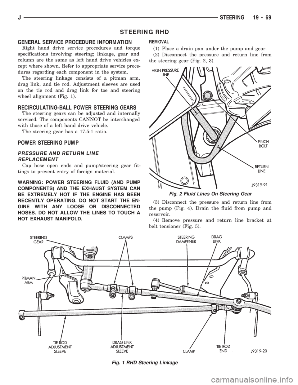
The steering linkage consists of a pitman arm,
drag link, and tie rod. Adjustment sleeves are used
on the tie rod and drag link for toe and steering
wheel alignment (Fig. 1).
RECIRCULATING-BALL POWER STEERING GEARS
The steering gears can be adjusted and internally
serviced. The components CANNOT be interchanged
with those of a left hand drive vehicle.
The steering gear has a 17.5:1 ratio.
POWER STEERING PUMP
PRESSURE AND RETURN LINE
REPLACEMENT
Cap hose open ends and pump/steering gear fit-
tings to prevent entry of foreign material.
WARNING: POWER STEERING FLUID (AND PUMP
COMPONENTS) AND THE EXHAUST SYSTEM CAN
BE EXTREMELY HOT IF THE ENGINE HAS BEEN
RECENTLY OPERATING. DO NOT START THE EN-
GINE WITH ANY LOOSE OR DISCONNECTED
HOSES. DO NOT ALLOW THE LINES TO TOUCH A
HOT EXHAUST MANIFOLD.REMOVAL
(1) Place a drain pan under the pump and gear.
(2) Disconnect the pressure and return line from
the steering gear (Fig. 2, 3).
(3) Disconnect the pressure and return line from
the pump (Fig. 4). Drain the fluid from pump and
reservoir.
(4) Remove pressure and return line bracket at
belt tensioner (Fig. 5).
Fig. 1 RHD Steering Linkage
Fig. 2 Fluid Lines On Steering Gear
JSTEERING 19 - 69
Page 1112 of 1784
TRANSMISSION AND TRANSFER CASE
CONTENTS
page page
30RH/32RH AUTOMATIC TRANSMISSION . . . 66
AW-4 AUTOMATIC TRANSMISSION........ 156AX 15 MANUAL TRANSMISSION.......... 32
AX 4/5 MANUAL TRANSMISSION........... 1
AX 4/5 MANUAL TRANSMISSION
INDEX
page page
Cleaning and Inspection................... 13
Gear Ratios............................. 2
General Information........................ 1
Recommended Lubricant.................... 2
Service Diagnosis......................... 2
Shift Pattern............................. 2Transmission Assembly and Adjustment....... 15
Transmission Disassembly and Overhaul........ 5
Transmission Identification................... 1
Transmission Installation.................... 4
Transmission Removal..................... 3
GENERAL INFORMATION
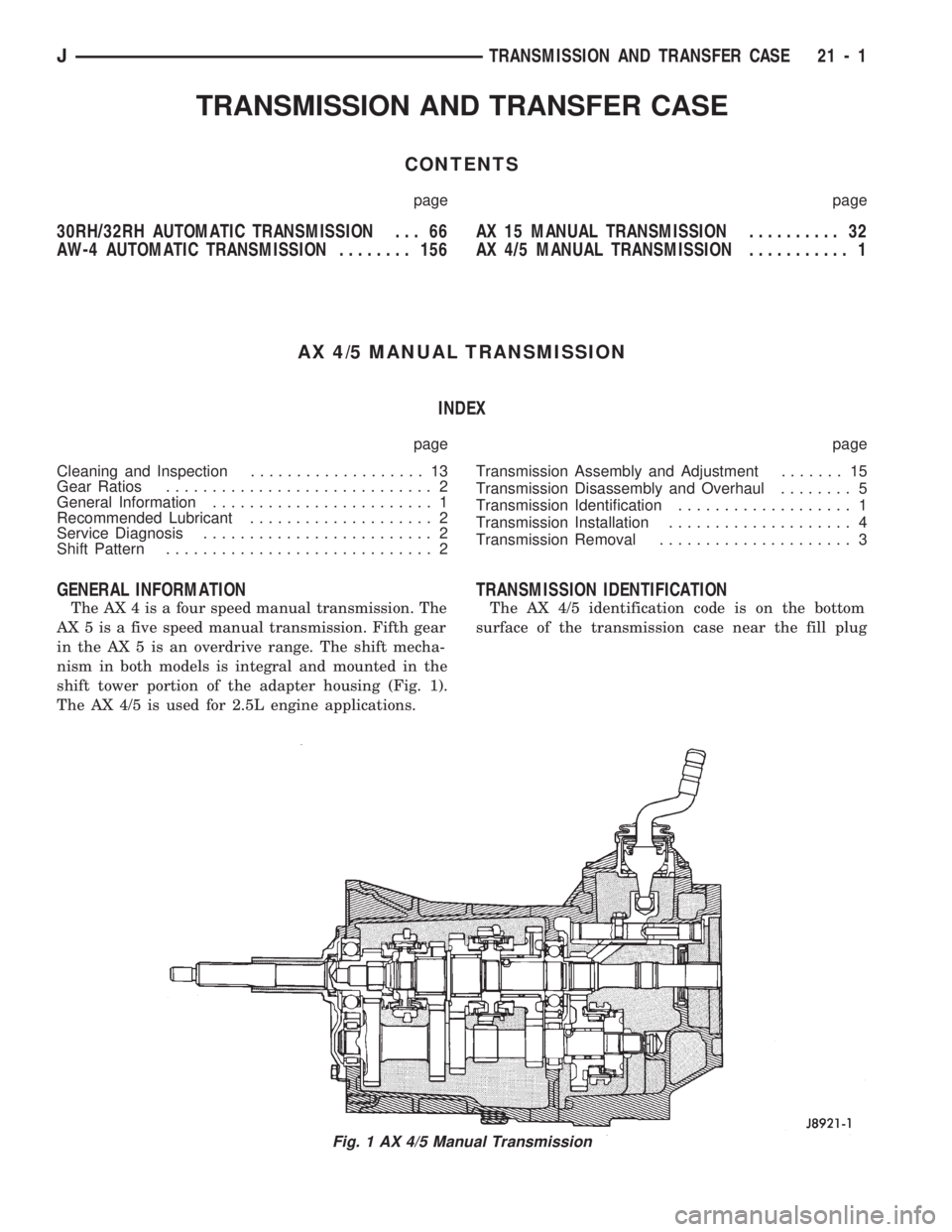
The AX 4 is a four speed manual transmission. The
AX 5 is a five speed manual transmission. Fifth gear
in the AX 5 is an overdrive range. The shift mecha-
nism in both models is integral and mounted in the
shift tower portion of the adapter housing (Fig. 1).
The AX 4/5 is used for 2.5L engine applications.
TRANSMISSION IDENTIFICATION
The AX 4/5 identification code is on the bottom
surface of the transmission case near the fill plug
Fig. 1 AX 4/5 Manual Transmission
JTRANSMISSION AND TRANSFER CASE 21 - 1
Page 1113 of 1784
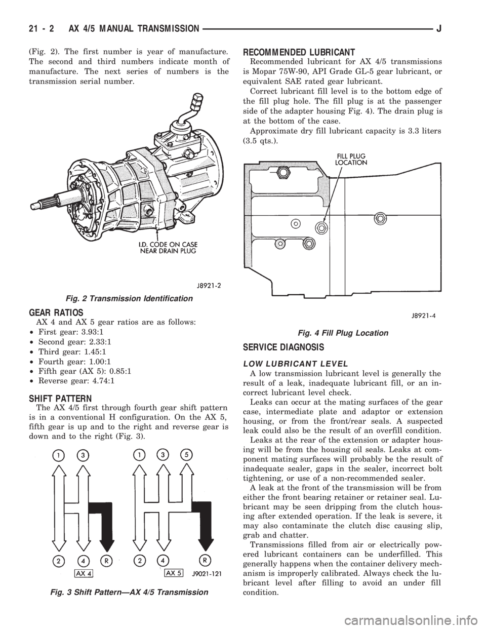
(Fig. 2). The first number is year of manufacture.
The second and third numbers indicate month of
manufacture. The next series of numbers is the
transmission serial number.
GEAR RATIOS
AX 4 and AX 5 gear ratios are as follows:
²First gear: 3.93:1
²Second gear: 2.33:1
²Third gear: 1.45:1
²Fourth gear: 1.00:1
²Fifth gear (AX 5): 0.85:1
²Reverse gear: 4.74:1
SHIFT PATTERN
The AX 4/5 first through fourth gear shift pattern
is in a conventional H configuration. On the AX 5,
fifth gear is up and to the right and reverse gear is
down and to the right (Fig. 3).
RECOMMENDED LUBRICANT
Recommended lubricant for AX 4/5 transmissions
is Mopar 75W-90, API Grade GL-5 gear lubricant, or
equivalent SAE rated gear lubricant.
Correct lubricant fill level is to the bottom edge of
the fill plug hole. The fill plug is at the passenger
side of the adapter housing Fig. 4). The drain plug is
at the bottom of the case.
Approximate dry fill lubricant capacity is 3.3 liters
(3.5 qts.).
SERVICE DIAGNOSIS
LOW LUBRICANT LEVEL
A low transmission lubricant level is generally the
result of a leak, inadequate lubricant fill, or an in-
correct lubricant level check.
Leaks can occur at the mating surfaces of the gear
case, intermediate plate and adaptor or extension
housing, or from the front/rear seals. A suspected
leak could also be the result of an overfill condition.
Leaks at the rear of the extension or adapter hous-
ing will be from the housing oil seals. Leaks at com-
ponent mating surfaces will probably be the result of
inadequate sealer, gaps in the sealer, incorrect bolt
tightening, or use of a non-recommended sealer.
A leak at the front of the transmission will be from
either the front bearing retainer or retainer seal. Lu-
bricant may be seen dripping from the clutch hous-
ing after extended operation. If the leak is severe, it
may also contaminate the clutch disc causing slip,
grab and chatter.
Transmissions filled from air or electrically pow-
ered lubricant containers can be underfilled. This
generally happens when the container delivery mech-
anism is improperly calibrated. Always check the lu-
bricant level after filling to avoid an under fill
condition.
Fig. 2 Transmission Identification
Fig. 3 Shift PatternÐAX 4/5 Transmission
Fig. 4 Fill Plug Location
21 - 2 AX 4/5 MANUAL TRANSMISSIONJ
Page 1142 of 1784
(15) Install vehicle speed sensor. Refer to proce-
dure in In-Vehicle Service section.
(16) Install clutch housing, release bearing, fork
and retainer clip.
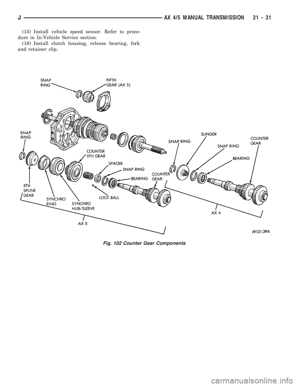
Fig. 102 Counter Gear Components
JAX 4/5 MANUAL TRANSMISSION 21 - 31
Page 1143 of 1784
AX 15 MANUAL TRANSMISSION
INDEX
page page
General Information....................... 32
Service Diagnosis........................ 33
Transmission Assembly and Adjustment....... 51
Transmission Disassembly and Overhaul....... 36
Transmission Gear Ratios.................. 33
Transmission Identification.................. 32Transmission InstallationÐAX 15............. 35
Transmission Lubricant.................... 33
Transmission RemovalÐAX 15.............. 34
Transmission Shift Pattern.................. 33
Transmission Switch and Plug Locations....... 33
GENERAL INFORMATION
The AX 15 is a 5-speed, synchromesh, manual
transmission. Fifth gear is an overdrive range with a
ratio of 0.79:1. The shift mechanism is integral and
mounted in the shift tower portion of the adapter
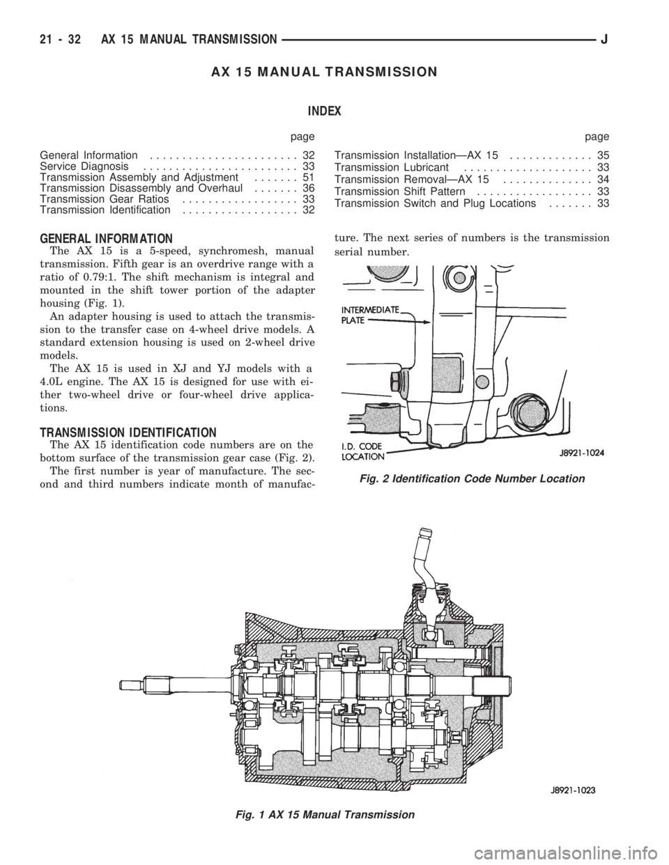
housing (Fig. 1).
An adapter housing is used to attach the transmis-
sion to the transfer case on 4-wheel drive models. A
standard extension housing is used on 2-wheel drive
models.
The AX 15 is used in XJ and YJ models with a
4.0L engine. The AX 15 is designed for use with ei-
ther two-wheel drive or four-wheel drive applica-
tions.
TRANSMISSION IDENTIFICATION
The AX 15 identification code numbers are on the
bottom surface of the transmission gear case (Fig. 2).
The first number is year of manufacture. The sec-
ond and third numbers indicate month of manufac-ture. The next series of numbers is the transmission
serial number.
Fig. 1 AX 15 Manual Transmission
Fig. 2 Identification Code Number Location
21 - 32 AX 15 MANUAL TRANSMISSIONJ
Page 1144 of 1784
TRANSMISSION SHIFT PATTERN
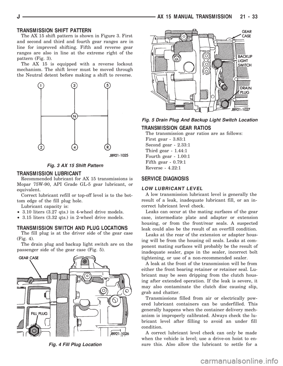
The AX 15 shift pattern is shown in Figure 3. First
and second and third and fourth gear ranges are in
line for improved shifting. Fifth and reverse gear
ranges are also in line at the extreme right of the
pattern (Fig. 3).
The AX 15 is equipped with a reverse lockout
mechanism. The shift lever must be moved through
the Neutral detent before making a shift to reverse.
TRANSMISSION LUBRICANT
Recommended lubricant for AX 15 transmissions is
Mopar 75W-90, API Grade GL-5 gear lubricant, or
equivalent.
Correct lubricant refill or top-off level is to the bot-
tom edge of the fill plug hole.
Lubricant capacity is:
²3.10 liters (3.27 qts.) in 4-wheel drive models.
²3.15 liters (3.32 qts.) in 2-wheel drive models.
TRANSMISSION SWITCH AND PLUG LOCATIONS
The fill plug is at the driver side of the gear case
(Fig. 4).
The drain plug and backup light switch are on the
passenger side of the gear case (Fig. 5).
TRANSMISSION GEAR RATIOS
The transmission gear ratios are as follows:
First gear - 3.83:1
Second gear - 2.33:1
Third gear - 1.44:1
Fourth gear - 1.00:1
Fifth gear - 0.79:1
Reverse - 4.22:1
SERVICE DIAGNOSIS
LOW LUBRICANT LEVEL
A low transmission lubricant level is generally the
result of a leak, inadequate lubricant fill, or an in-
correct lubricant level check.
Leaks can occur at the mating surfaces of the gear
case, intermediate plate and adapter or extension
housing, or from the front/rear seals. A suspected
leak could also be the result of an overfill condition.
Leaks at the rear of the extension or adapter hous-
ing will be from the housing oil seals. Leaks at com-
ponent mating surfaces will probably be the result of
inadequate sealer, gaps in the sealer, incorrect bolt
tightening, or use of a non-recommended sealer.
A leak at the front of the transmission will be from
either the front bearing retainer or retainer seal. Lu-
bricant may be seen dripping from the clutch hous-
ing after extended operation. If the leak is severe, it
may also contaminate the clutch disc causing slip,
grab and chatter.
Transmissions filled from air or electrically pow-
ered lubricant containers can be underfilled. This
generally happens when the container delivery mech-
anism is improperly calibrated. Always check the lu-
bricant level after filling to avoid an under fill
condition.
A correct lubricant level check can only be made
when the vehicle is level; use a drive-on hoist to en-
sure this. Also allow the lubricant to settle for a
Fig. 3 AX 15 Shift Pattern
Fig. 4 Fill Plug Location
Fig. 5 Drain Plug And Backup Light Switch Location
JAX 15 MANUAL TRANSMISSION 21 - 33
Page 1155 of 1784
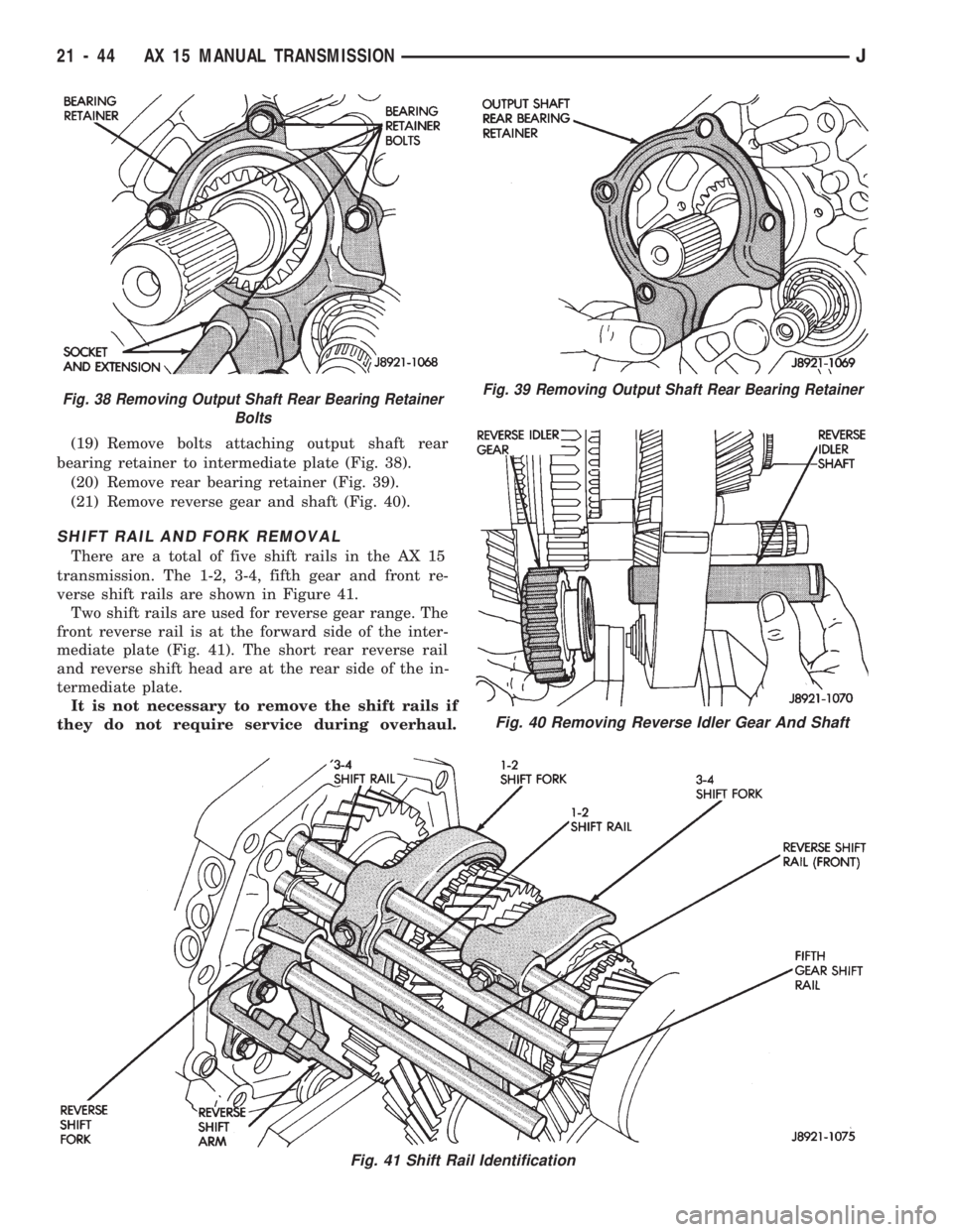
(19) Remove bolts attaching output shaft rear
bearing retainer to intermediate plate (Fig. 38).
(20) Remove rear bearing retainer (Fig. 39).
(21) Remove reverse gear and shaft (Fig. 40).
SHIFT RAIL AND FORK REMOVAL
There are a total of five shift rails in the AX 15
transmission. The 1-2, 3-4, fifth gear and front re-
verse shift rails are shown in Figure 41.
Two shift rails are used for reverse gear range. The
front reverse rail is at the forward side of the inter-
mediate plate (Fig. 41). The short rear reverse rail
and reverse shift head are at the rear side of the in-
termediate plate.
It is not necessary to remove the shift rails if
they do not require service during overhaul.
Fig. 38 Removing Output Shaft Rear Bearing Retainer
BoltsFig. 39 Removing Output Shaft Rear Bearing Retainer
Fig. 40 Removing Reverse Idler Gear And Shaft
Fig. 41 Shift Rail Identification
21 - 44 AX 15 MANUAL TRANSMISSIONJ
Page 1177 of 1784
30RH/32RH AUTOMATIC TRANSMISSION
INDEX
page page
General Information....................... 66
Parts Interchangeability.................... 66
Recommended Fluid...................... 66
Specifications and Band Adjustments......... 66Torque Converter........................ 66
Transmission Application................... 66
Transmission Controls and Components....... 66
Transmission Identification.................. 66
GENERAL INFORMATION
TRANSMISSION APPLICATION
Chrysler 30RH and 32RH automatic transmissions
are used in XJ/YJ models. Both transmissions are
three speed, automatics with a gear-type oil pump,
two clutches and bands and a planetary gear system
(Fig. 1). The 30RH is used with 2.5L engines and the
32RH is used with 4.0L engines.
TORQUE CONVERTER
A three element, torque converter is used for all
applications. The converter consists of the impeller,
stator, and turbine.
The converter used with all 30RH/32RH transmis-
sions is equipped with a converter clutch. The clutch
is engaged by an electrical solenoid and mechanical
clutch module on the valve body. The solenoid is op-
erated by the powertrain control module.
The impeller is connected to the engine crankshaft
through the front cover which is welded to the impel-
ler. The turbine is splined to the transmission input
shaft and the stator is splined to the transmission re-
action shaft.
The torque converter is a welded assembly and is
not a repairable component. The converter is serviced
as an assembly.
RECOMMENDED FLUID
The recommended (and preferred) fluid for 30RH/
32RH transmissions is Mopar ATF Plus, Type 7176.
Mopar Dexron II can be used but only if ATF Plus
is not available.
Transmission fluid capacity is approximately 17
pints (7.9 liters). This is the approximate amount of
fluid required to fill the transmission and torque con-
verter after overhaul.
TRANSMISSION IDENTIFICATION
The transmission identification numbers are
stamped on the left side of the case just above the oil
pan gasket surface (Fig. 2). The first set of numbers
is the transmission part number. The next set of code
numbers set is the date of build. The final set of code
numbers represents the transmission serial number.
SPECIFICATIONS AND BAND ADJUSTMENTS
Service specifications and torque values are located
at the end of this group. Refer to the specifications
during service operations.
The band adjustment specifications for 1994
transmissions are different. Refer to the front
and rear band adjustment procedures in the In-
Vehicle Service section for details.
PARTS INTERCHANGEABILITY
The 1994 version of the 30RH (A904) transmission
is similar to previous models in appearance only. The
current 30RH is quite different and interchanging
new/old parts is definitely not recommended. Differ-
ent component dimensions, fluid passages, input/out-
put shafts, cases, bands, valve bodies and governor
assemblies are just a few of the changed items. The
32RH transmission is also different from previous
models and the same recommendations apply here as
well.
CAUTION: On YJ models with a 2.5L engine and
30RH transmission, special bolts are used to attach
the driveplate to the crankshaft. These bolts have a
smaller hex head for torque converter clearance.
DO NOT interchange these bolts with similar size
bolts for any reason.
TRANSMISSION CONTROLS AND COMPONENTS
The transmission hydraulic control system per-
forms five basic functions, which are:
²pressure supply
²pressure regulation
²flow control
²clutch/band apply and release
²lubrication
Pressure Supply And Regulation
The oil pump generates the fluid working pressure
needed for operation and lubrication. The pump is
driven by the torque converter. The converter is con-
nected to the engine crankshaft through the drive-
plate.
The pressure regulator valve maintains operating
(line) pressure. The regulator valve is located in the
valve body. The amount of line pressure developed is
21 - 66 30RH/32RH AUTOMATIC TRANSMISSIONJ