1994 JEEP CHEROKEE service
[x] Cancel search: servicePage 1181 of 1784
(8) Check fluid condition. Fluid should be dark to
light red in color and free of dirt or debris.
(9) If fluid is discolored or smells burned but trans-
mission operation was OK, check cooler flow, flush
cooler and lines and change fluid and filter. Then
road test again to confirm proper operation.
(10) If fluid is black or dark brown, burned/turned
to sludge, contains large quantities of metal or fric-
tion material particles, transmission will need over-
haul. Especially if problems were evident during
road test and preliminary diagnosis. Fluid cooler
should also be flow tested and flushed if necessary.
EFFECTS OF INCORRECT FLUID LEVEL
A low fluid level allows the pump to take in air
along with the fluid. Air in the fluid will cause fluid
pressures to be low and develop slower than normal.
If the transmission is overfilled, the gears churn
the fluid into foam. This aerates the fluid causing
the same conditions that occur with a low level.
In either case, air bubbles cause fluid overheating,
oxidation and varnish buildup which interferes with
valve, clutch and servo operation. Foaming also
causes fluid expansion which can result in fluid over-
flow from the transmission vent or fill tube. Fluid
overflow can easily be mistaken for a leak if inspec-
tion is not careful.
TRANSMISSION THROTTLE VALVE CABLE
ADJUSTMENT
Throttle cable adjustment is important to proper
operation. This adjustment positions the throttle
valve which controls shift speed, quality and part
throttle downshift sensitivity.
If cable adjustment setting is too short, early shifts
and slippage between shifts may occur. If the setting
is too long, shifts may be delayed and part throttle
downshifts may be very sensitive. Refer to the In-Ve-
hicle Service section for adjustment procedure.
GEARSHIFT LINKAGE
Gearshift linkage adjustment is important because
it positions the valve body manual valve. Incorrect
adjustment will cause creeping in Neutral, prema-
ture clutch wear, delayed engagement in any gear, or
a no-start in Park or Neutral position.
Proper operation of the neutral start switch will
provide a quick check of linkage adjustment. Refer to
the In-Vehicle Service section for adjustment proce-
dure.
ROAD TEST
Before road testing, be sure the fluid level and all
linkage adjustments have been checked and adjusted
if necessary.
Observe engine performance during the road test.
A poorly tuned engine will not allow an accurate
analysis of transmission operation.Operate the transmission in all gear ranges. Check
for slippage and shift variations. Note whether the
shifts are harsh, spongy, delayed, early, or if part
throttle downshifts are sensitive.
Watch closely for slippage or engine flare which
usually indicates clutch, band or overrunning clutch
problems. If the condition is advanced, an overhaul
may be necessary to restore normal operation.
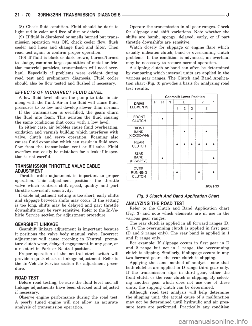
A slipping clutch or band can often be determined
by comparing which internal units are applied in the
various gear ranges. The Clutch and Band Applica-
tion chart (Fig. 3) provides a basis for analyzing road
test results.
ANALYZING THE ROAD TEST
Refer to the Clutch and Band Application chart
(Fig. 3) and note which elements are in use in the
various gear ranges.
The rear clutch is applied in all forward ranges (D,
2, 1). The overrunning clutch is applied in first gear
(D and 2 range only). The rear band is applied in 1
and R range only.
For example: If slippage occurs in first gear in D
and 2 range but not in 1 range, the overrunning
clutch is slipping. Similarly, if slippage occurs in any
two forward gears, the rear clutch is slipping.
Applying the same method of analysis, note that
both clutches are applied in D range third gear only.
If the transmission slips in third gear, either the
front clutch or the rear clutch is slipping. By select-
ing another gear which does not use one of these
units, the slipping clutch can be determined.
Although road test analysis will help determine
the slipping unit, the actual cause of a malfunction
may not be determined until hydraulic and air pres-
sure tests are performed. Practically any condition
Fig. 3 Clutch And Band Application Chart
21 - 70 30RH/32RH TRANSMISSION DIAGNOSISJ
Page 1183 of 1784
(5) Line pressure should be 54-60 psi (372-414
kPa) with throttle lever forward and gradually in-
crease to 90-96 psi (620-662 kPa) as lever is moved
rearward.
Test Three-Transmission In D Range
This test checks pressure regulation and con-
dition of the front and rear clutch circuits.
Both test gauges are required for this test.
(1) Connect one test gauge to line pressure port
and other gauge to front servo pressure port (Fig. 4).
Either gauge can be used at either port.
(2) Start and run engine at 1600 rpm.
(3) Move selector lever two detents rearward from
full forward position. This is D range.
(4) Read pressures on both gauges as transmission
throttle lever is moved from full forward to full rear-
ward position.
(5) Line pressure should be 54-60 psi (372-414
kPa) with throttle lever forward and gradually in-
crease as lever is moved rearward.
(6) Front servo is pressurized only in D range and
should be same as line pressure within 3 psi (21
kPa), up to downshift point.
Test Four-Transmission In Reverse
This test checks pump output, pressure regu-
lation and the front clutch and rear servo cir-
cuits. Use 300 psi Pressure Test Gauge C-3293
for this test.
(1) Connect pressure test gauge to rear servo port
(Fig. 5).
(2) Start and run engine at 1600 rpm for test.
(3) Move valve body selector lever four detents
rearward from full forward position. This is Reverse
range.
(4) Move throttle lever all way forward then all the
way rearward and note gauge readings.
(5) Pressure should be 145 - 175 psi (1000-1207
kPa) with lever forward and increase to 230 - 280 psi
(1586-1931 kPa) as lever is moved rearward.
Test Five-Governor Pressure
This test checks governor operation by mea-
suring governor pressure response to changes
in engine speed. It is usually not necessary to
check governor operation unless shift speeds
are incorrect or if the transmission will not
shift up or down. Use 100 psi Pressure Test
Gauge C-3292 for this test.
(1) Connect test gauge to governor pressure port
(Figs. 5 and 6).
(2) Move selector lever to D range.
(3) Apply service brakes. Start and run engine at
curb idle speed and note pressure. At idle and with
wheels stopped, pressure should be zero to 1-1/2 psi
maximum. If pressure exceeds this figure, governor
valve or weights are sticking open.(4) Slowly increase engine speed and observe
speedometer and pressure test gauge. Governor pres-
sure should increase in proportion to vehicle speed
(approximately 1 psi for every 1 mph shown on
speedometer).
(5) Governor pressure rise should be smooth and
drop back to 0 to 1-1/2 psi when throttle is closed
and wheels are stopped.
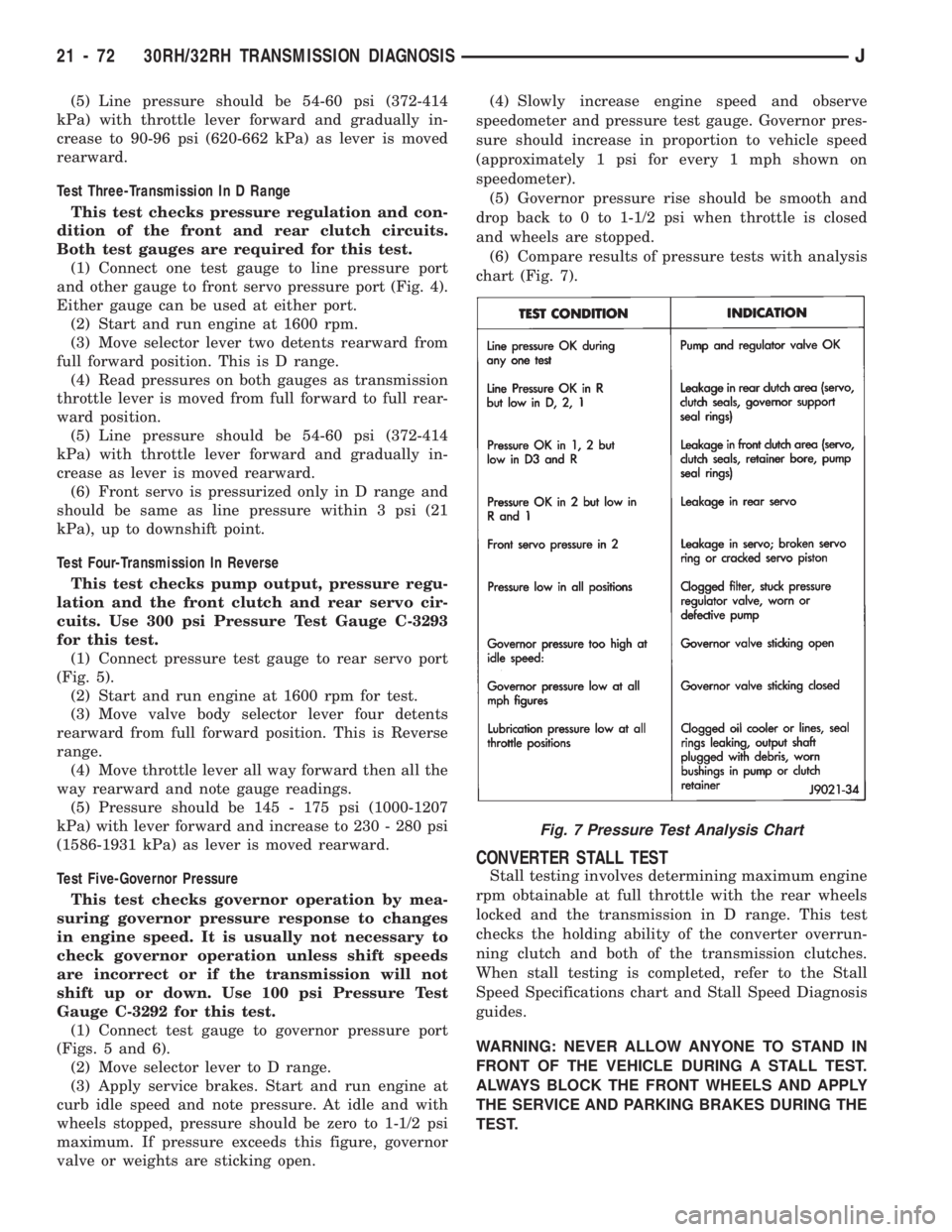
(6) Compare results of pressure tests with analysis
chart (Fig. 7).
CONVERTER STALL TEST
Stall testing involves determining maximum engine
rpm obtainable at full throttle with the rear wheels
locked and the transmission in D range. This test
checks the holding ability of the converter overrun-
ning clutch and both of the transmission clutches.
When stall testing is completed, refer to the Stall
Speed Specifications chart and Stall Speed Diagnosis
guides.
WARNING: NEVER ALLOW ANYONE TO STAND IN
FRONT OF THE VEHICLE DURING A STALL TEST.
ALWAYS BLOCK THE FRONT WHEELS AND APPLY
THE SERVICE AND PARKING BRAKES DURING THE
TEST.
Fig. 7 Pressure Test Analysis Chart
21 - 72 30RH/32RH TRANSMISSION DIAGNOSISJ
Page 1184 of 1784
STALL TEST PROCEDURE
(1) Connect tachometer to engine.
(2) Check and adjust transmission fluid level.
(3) Start and run engine until transmission fluid
reaches normal operating temperature.
(4) Block front wheels.
(5) Fully apply service and parking brakes.
(6) Open throttle completely for no more than five
seconds and record maximum engine rpm registered
on tachometer.
CAUTION: Stall testing causes a rapid increase in
transmission fluid temperature. Do not hold the
throttle open any longer than five seconds. If more
than one stall test is required, run the engine at
1000 rpm with the transmission in Neutral for at
least 20 seconds to cool the fluid.
(7) If engine speed exceeds maximum shown in
stall speed chart, release accelerator immediately.
This indicates that transmission clutch slippage is
occurring.
(8) Shift transmission into Neutral. Run engine for
20 seconds to cool fluid. Then stop engine, shift
transmission into Park and release brakes.
(9) Stall speeds should be in 1700-2000 rpm range.
(10) Refer to Stall Test Diagnosis.
STALL TEST DIAGNOSIS
Stall Speed Too High
If the stall speed exceeds specifications by more
than 200 rpm, transmission clutch slippage is indi-
cated.
Stall Speed Too Low
Low stall speeds with a properly tuned engine in-
dicate a torque converter overrunning clutch prob-
lem. The condition should be confirmed by road
testing prior to converter replacement.
The converter overrunning clutch is slipping when
stall speeds are 250 to 350 rpm below specified min-
imum. And when the vehicle operates properly at
highway speeds but has poor low speed acceleration.
Stall Speed Normal
If stall speeds are normal but abnormal throttle
opening is required to maintain highway speeds, the
converter overrunning clutch is seized and the torque
converter must be replaced.
Converter Noise During Test
A whining noise caused by fluid flow is normal
during a stall test. However, loud metallic noises in-
dicate a damaged converter. To confirm that noise is
originating from the converter, operate the vehicle at
light throttle in Drive and Neutral on a hoist and lis-
ten for noise coming from the converter housing.
AIR PRESSURE TEST
Air pressure testing can be used to check clutch
and band operation with the transmission either in
the vehicle, or on the work bench as a final check af-
ter overhaul.
Air pressure testing requires that the oil pan and
valve body be removed from the transmission.
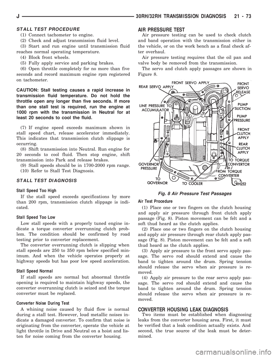
The servo and clutch apply passages are shown in
Figure 8.
Air Test Procedure
(1) Place one or two fingers on the clutch housing
and apply air pressure through front clutch apply
passage (Fig. 8). Piston movement can be felt and a
soft thud heard as the clutch applies.
(2) Place one or two fingers on the clutch housing
and apply air pressure through rear clutch apply pas-
sage (Fig. 8). Piston movement can be felt and a soft
thud heard as the clutch applies.
(3) Apply air pressure to the front servo apply pas-
sage. The servo rod should extend and cause the
band to tighten around the drum. Spring tension
should release the servo when air pressure is re-
moved.
(4) Apply air pressure to the rear servo apply pas-
sage. The servo rod should extend and cause the
band to tighten around the drum. Spring tension
should release the servo when air pressure is re-
moved.
CONVERTER HOUSING LEAK DIAGNOSIS
Two items must be established when diagnosing
leaks from the converter housing area. First, it must
be verified that a leak condition actually exists. And
second, the true source of the leak must be deter-
mined.
Fig. 8 Air Pressure Test Passages
J30RH/32RH TRANSMISSION DIAGNOSIS 21 - 73
Page 1207 of 1784
30RH/32RH IN-VEHICLE SERVICE
INDEX
page page
Checking Fluid Level and Condition........... 96
Front Band Adjustment.................... 99
Gearshift Linkage Adjustment (YJ)............ 96
Governor and Park Gear Service............ 101
Oil Filter Replacement.................... 100
Park Interlock Cable Adjustment (XJ)......... 97
Park Lock Component Replacement......... 102
Park/Neutral Position Switch Service......... 103
Rear Band Adjustment.................... 99
Recommended Fluid...................... 96
Servicing Transmission Cooler Lines and Fittings. 106
Shift Cable Adjustment (XJ)................ 97
Speedometer Service.................... 103
Transmission Cooler Flow Testing........... 106
Transmission Cooler Reverse Flushing....... 105
Transmission Throttle Cable Adjustment (XJ/YJ) . 98
Valve Body Installation................... 101
Valve Body Removal..................... 100
Valve Body Service...................... 100
RECOMMENDED FLUID
The recommended and preferred fluid for 30RH/
32RH transmissions is Mopar ATF Plus, Type 7176.
Mopar Dexron II is acceptable but should only be
used when ATF Plus is not available.
Transmission fluid capacity is approximately 17
pints (7.9 liters). This is the approximate amount of
fluid required to fill the transmission and torque con-
verter after overhaul.
CHECKING FLUID LEVEL AND CONDITION
(1) Position vehicle on flat, level surface. This is
important in obtaining an accurate fluid level check.
(2) To avoid false readings, which could produce
under or over fill condition, do not check level until
fluid is at normal operating temperature.
(3) Shift transmission into Neutral.
(4) Apply parking brakes.
(5) Operate engine at curb idle speed.
WARNING: WHEN PERFORMING UNDERHOOD OP-
ERATIONS WITH THE ENGINE RUNNING, KEEP
YOUR HANDS WELL AWAY FROM HOT OR ROTAT-
ING ENGINE COMPONENTS. DO NOT WEAR
LOOSE ARTICLES OF CLOTHING WHICH COULD
BECOME ENTANGLED IN ENGINE COMPONENTS
OR ACCESSORIES.
(6) Shift transmission through all gear ranges and
back to Neutral (leave engine running).
(7) Clean exterior of dipstick cap and fill tube be-
fore removing transmission dipstick.
(8) Remove dipstick and inspect fluid level.
²Correct level is to FULL mark
²Acceptable level is between ADD and FULL marks
(9) Check fluid condition. Fluid should be dark to
light red in color and free of dirt or debris.
(10) If fluid is discolored or smells burned but
transmission operation was OK, check cooler flow,
flush cooler and lines and change fluid and filter.
Then road test again to confirm proper operation.(11) If fluid is black or dark brown, burned/turned
to sludge, contains large quantities of metal or fric-
tion material particles, transmission will need over-
haul. Especially if problems were evident during
road test and preliminary diagnosis. Fluid cooler
should also be flow tested and flushed if necessary.
GEARSHIFT LINKAGE ADJUSTMENT (YJ)
(1) Check linkage adjustment by starting engine in
Park and Neutral.
(2) Adjustment is OK if engine starts only in park
and Neutral. Adjustment is incorrect if engine starts
in one but not both positions.
(3) If engine starts in any position other than Park
or Neutral, or if engine will not start at all, park/
neutral position switch may be faulty.
(4) Shift transmission into Park.
(5) Raise vehicle.
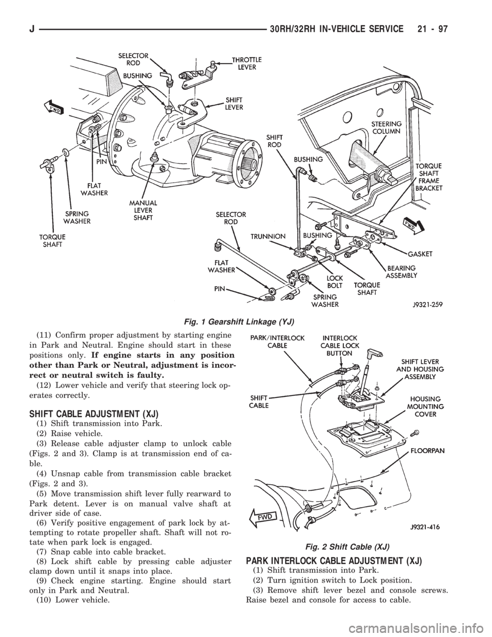
(6) Check condition of shift rods, bellcrank, bell-
crank brackets and linkage bushings/grommets (Fig.
1). Tighten, repair, replace worn, damaged parts. Do
not attempt adjustment if linkage components are
worn or damaged.
(7) Loosen shift rod trunnion lock bolt or nut. Be
sure upper shift rod slides freely in trunnion (Fig. 1).
Also be sure shift rods and bellcrank rotate freely
and do not bind at any point.
(8) Verify that manual lever is in Park detent
(Fig. 1). Move lever all the way rearward to be sure
it is in Park.
(9) Check for positive engagement of park lock by
attempting to rotate propeller shaft. Shaft will not
turn when park pawl is engaged.
(10) Adjust shift rod trunnion to a obtain free pin
fit in bellcrank arm and tighten trunnion lock bolt or
nut. Prevent shift rod from turning while tightening
bolt or nut. Gearshift linkage lash must be elimi-
nated to obtain proper adjustment. Eliminate lash by
pulling downward on shift rod and pressing upward
on bellcrank.
21 - 96 30RH/32RH IN-VEHICLE SERVICEJ
Page 1208 of 1784
(11) Confirm proper adjustment by starting engine
in Park and Neutral. Engine should start in these
positions only.If engine starts in any position
other than Park or Neutral, adjustment is incor-
rect or neutral switch is faulty.
(12) Lower vehicle and verify that steering lock op-
erates correctly.
SHIFT CABLE ADJUSTMENT (XJ)
(1) Shift transmission into Park.
(2) Raise vehicle.
(3) Release cable adjuster clamp to unlock cable
(Figs. 2 and 3). Clamp is at transmission end of ca-
ble.
(4) Unsnap cable from transmission cable bracket
(Figs. 2 and 3).
(5) Move transmission shift lever fully rearward to
Park detent. Lever is on manual valve shaft at
driver side of case.
(6) Verify positive engagement of park lock by at-
tempting to rotate propeller shaft. Shaft will not ro-
tate when park lock is engaged.
(7) Snap cable into cable bracket.
(8) Lock shift cable by pressing cable adjuster
clamp down until it snaps into place.
(9) Check engine starting. Engine should start
only in Park and Neutral.
(10) Lower vehicle.
PARK INTERLOCK CABLE ADJUSTMENT (XJ)
(1) Shift transmission into Park.
(2) Turn ignition switch to Lock position.
(3) Remove shift lever bezel and console screws.
Raise bezel and console for access to cable.
Fig. 1 Gearshift Linkage (YJ)
Fig. 2 Shift Cable (XJ)
J30RH/32RH IN-VEHICLE SERVICE 21 - 97
Page 1209 of 1784
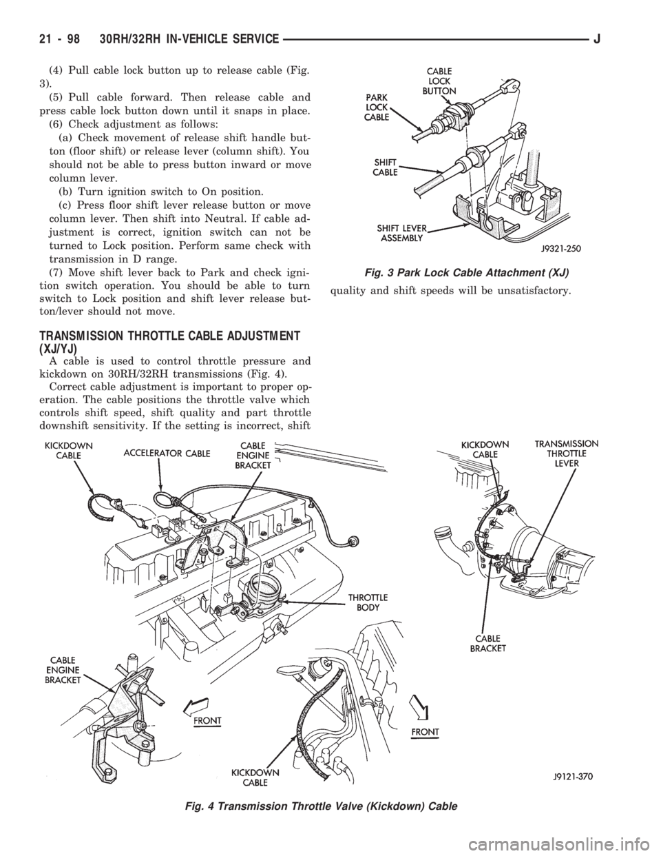
(4) Pull cable lock button up to release cable (Fig.
3).
(5) Pull cable forward. Then release cable and
press cable lock button down until it snaps in place.
(6) Check adjustment as follows:
(a) Check movement of release shift handle but-
ton (floor shift) or release lever (column shift). You
should not be able to press button inward or move
column lever.
(b) Turn ignition switch to On position.
(c) Press floor shift lever release button or move
column lever. Then shift into Neutral. If cable ad-
justment is correct, ignition switch can not be
turned to Lock position. Perform same check with
transmission in D range.
(7) Move shift lever back to Park and check igni-
tion switch operation. You should be able to turn
switch to Lock position and shift lever release but-
ton/lever should not move.
TRANSMISSION THROTTLE CABLE ADJUSTMENT
(XJ/YJ)
A cable is used to control throttle pressure and
kickdown on 30RH/32RH transmissions (Fig. 4).
Correct cable adjustment is important to proper op-
eration. The cable positions the throttle valve which
controls shift speed, shift quality and part throttle
downshift sensitivity. If the setting is incorrect, shiftquality and shift speeds will be unsatisfactory.
Fig. 3 Park Lock Cable Attachment (XJ)
Fig. 4 Transmission Throttle Valve (Kickdown) Cable
21 - 98 30RH/32RH IN-VEHICLE SERVICEJ
Page 1210 of 1784
THROTTLE CABLE ADJUSTMENT
PROCEDURE
Cable adjustment is performed entirely in the
engine compartment. It is not necessary to raise
the vehicle for access to any other components.
(1) Shift transmission into Park and shut engine
off.
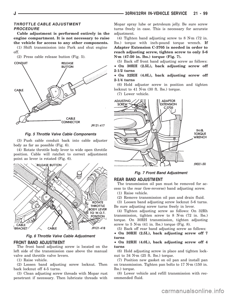
(2) Press cable release button (Fig. 5).
(3) Push cable conduit back into cable adjuster
body as far as possible (Fig. 6).
(4) Rotate throttle body lever to wide open throttle
position. Cable will ratchet to correct adjustment
point as lever is rotated (Fig. 6).
FRONT BAND ADJUSTMENT
The front band adjusting screw is located on the
left side of the transmission case above the manual
valve and throttle valve levers.
(1) Raise vehicle.
(2) Loosen band adjusting screw locknut. Then
back locknut off 4-5 turns.
(3) Clean adjusting screw threads with Mopar rust
penetrant if necessary. Then lubricate threads withMopar spray lube or petroleum jelly. Be sure screw
turns freely in case. This is necessary for accurate
adjustment.
(4) Tighten band adjusting screw to 8 Nzm (72 in.
lbs.) torque with inch-pound torque wrench.If
Adapter Extension C-3705 is needed in order to
reach adjusting screw, tighten screw to only 5-6
Nzm (47-50 in. lbs.) torque (Fig. 7).
(5) Back off front band adjusting screw as follows:
²On 30RH (2.5L), back adjusting screw off
2-1/2 turns
²On 32RH (4.0L), back adjusting screw off
2-1/4 turns
(6) Hold adjuster screw in position and tighten
locknut to 41 Nzm (30 ft. lbs.) torque.
(7) Lower vehicle.
REAR BAND ADJUSTMENT
The transmission oil pan must be removed for ac-
cess to the rear (low-reverse) band adjusting screw.
(1) Raise vehicle.
(2) Remove transmission oil pan and drain fluid.
(3) Loosen band adjusting screw locknut 5-6 turns.
Be sure adjusting screw turns freely in lever.
(4) Tighten adjusting screw as follows: On 32Rh
transmission, tighten screw to 8 Nzm (72 in. lbs.)
torque. On 30RH transmission, tighten adjusting
screw to 5 Nzm (41 in. lbs.) torque (Fig. 8).
(5) Back off rear band adjusting screw as follows:
²On 30RH (2.5L), back adjusting screw off 7
turns
²On 32RH (4.0L), back adjusting screw off 4
turns
(6) Hold adjusting screw in place and tighten lock-
nut to 34 Nzm (25 ft. lbs.) torque.
(7) Position new gasket on oil pan and install pan
on transmission. Tighten pan bolts to 17 Nzm (150 in.
lbs.) torque.
(8) Lower vehicle and refill transmission with rec-
ommended fluid.
Fig. 5 Throttle Valve Cable Components
Fig. 6 Throttle Valve Cable Adjustment
Fig. 7 Front Band Adjustment
J30RH/32RH IN-VEHICLE SERVICE 21 - 99
Page 1211 of 1784
OIL FILTER REPLACEMENT
(1) Raise vehicle.
(2) Remove oil pan and drain fluid.
(3) Remove filter screws and remove oil filter (Fig.
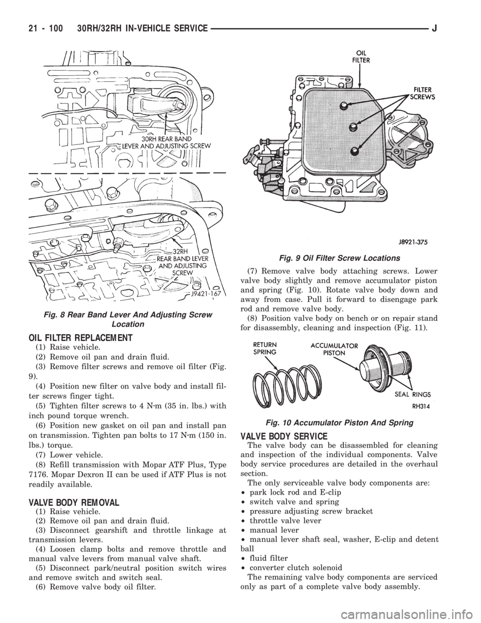
9).
(4) Position new filter on valve body and install fil-
ter screws finger tight.
(5) Tighten filter screws to 4 Nzm (35 in. lbs.) with
inch pound torque wrench.
(6) Position new gasket on oil pan and install pan
on transmission. Tighten pan bolts to 17 Nzm (150 in.
lbs.) torque.
(7) Lower vehicle.
(8) Refill transmission with Mopar ATF Plus, Type
7176. Mopar Dexron II can be used if ATF Plus is not
readily available.
VALVE BODY REMOVAL
(1) Raise vehicle.
(2) Remove oil pan and drain fluid.
(3) Disconnect gearshift and throttle linkage at
transmission levers.
(4) Loosen clamp bolts and remove throttle and
manual valve levers from manual valve shaft.
(5) Disconnect park/neutral position switch wires
and remove switch and switch seal.
(6) Remove valve body oil filter.(7) Remove valve body attaching screws. Lower
valve body slightly and remove accumulator piston
and spring (Fig. 10). Rotate valve body down and
away from case. Pull it forward to disengage park
rod and remove valve body.
(8) Position valve body on bench or on repair stand
for disassembly, cleaning and inspection (Fig. 11).
VALVE BODY SERVICE
The valve body can be disassembled for cleaning
and inspection of the individual components. Valve
body service procedures are detailed in the overhaul
section.
The only serviceable valve body components are:
²park lock rod and E-clip
²switch valve and spring
²pressure adjusting screw bracket
²throttle valve lever
²manual lever
²manual lever shaft seal, washer, E-clip and detent
ball
²fluid filter
²converter clutch solenoid
The remaining valve body components are serviced
only as part of a complete valve body assembly.
Fig. 9 Oil Filter Screw Locations
Fig. 10 Accumulator Piston And Spring
Fig. 8 Rear Band Lever And Adjusting Screw
Location
21 - 100 30RH/32RH IN-VEHICLE SERVICEJ