1994 JEEP CHEROKEE service
[x] Cancel search: servicePage 901 of 1784
(3) Check for rocker arm bridges which are caus-
ing misalignment of the rocker arm to valve tip area.
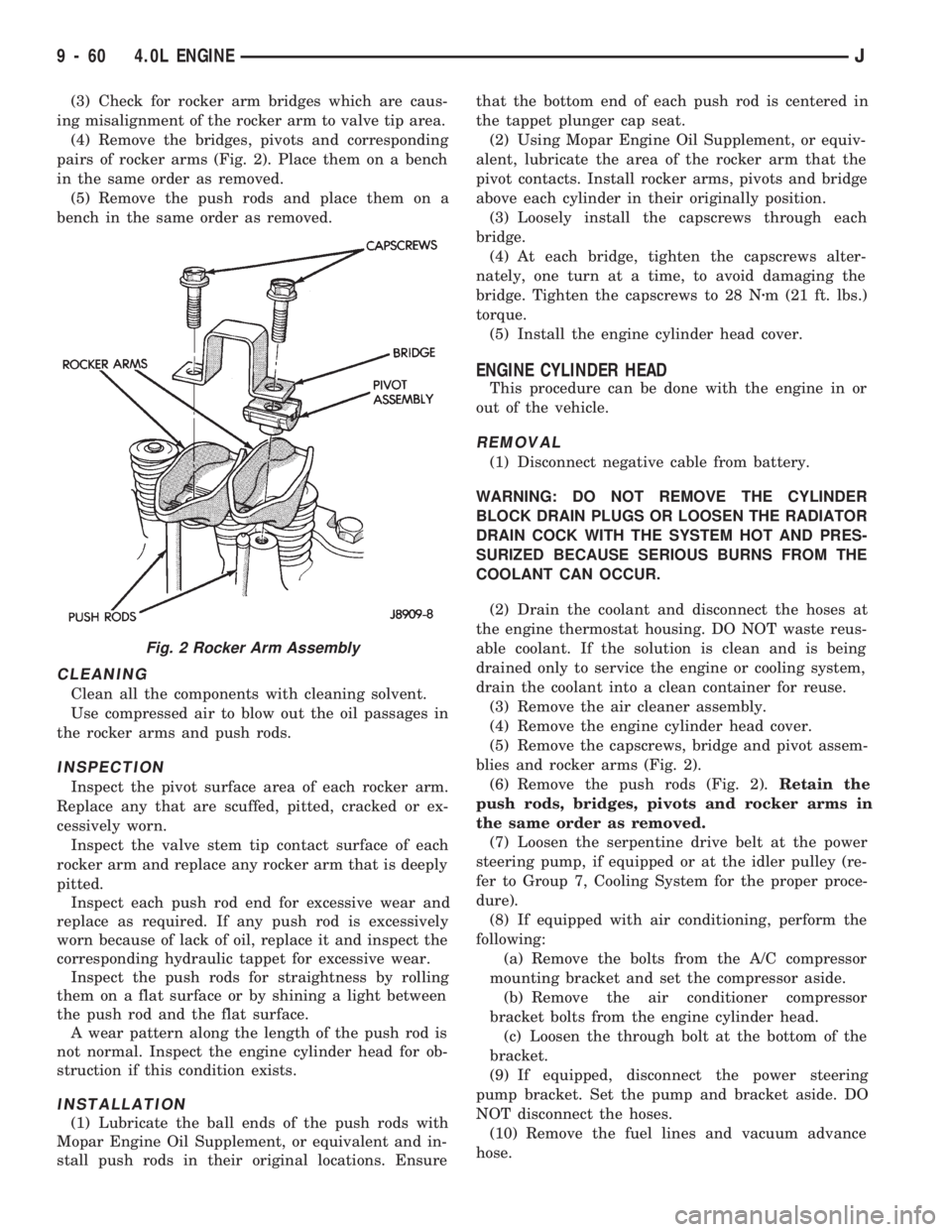
(4) Remove the bridges, pivots and corresponding
pairs of rocker arms (Fig. 2). Place them on a bench
in the same order as removed.
(5) Remove the push rods and place them on a
bench in the same order as removed.
CLEANING
Clean all the components with cleaning solvent.
Use compressed air to blow out the oil passages in
the rocker arms and push rods.
INSPECTION
Inspect the pivot surface area of each rocker arm.
Replace any that are scuffed, pitted, cracked or ex-
cessively worn.
Inspect the valve stem tip contact surface of each
rocker arm and replace any rocker arm that is deeply
pitted.
Inspect each push rod end for excessive wear and
replace as required. If any push rod is excessively
worn because of lack of oil, replace it and inspect the
corresponding hydraulic tappet for excessive wear.
Inspect the push rods for straightness by rolling
them on a flat surface or by shining a light between
the push rod and the flat surface.
A wear pattern along the length of the push rod is
not normal. Inspect the engine cylinder head for ob-
struction if this condition exists.
INSTALLATION
(1) Lubricate the ball ends of the push rods with
Mopar Engine Oil Supplement, or equivalent and in-
stall push rods in their original locations. Ensurethat the bottom end of each push rod is centered in
the tappet plunger cap seat.
(2) Using Mopar Engine Oil Supplement, or equiv-
alent, lubricate the area of the rocker arm that the
pivot contacts. Install rocker arms, pivots and bridge
above each cylinder in their originally position.
(3) Loosely install the capscrews through each
bridge.
(4) At each bridge, tighten the capscrews alter-
nately, one turn at a time, to avoid damaging the
bridge. Tighten the capscrews to 28 Nzm (21 ft. lbs.)
torque.
(5) Install the engine cylinder head cover.
ENGINE CYLINDER HEAD
This procedure can be done with the engine in or
out of the vehicle.
REMOVAL
(1) Disconnect negative cable from battery.
WARNING: DO NOT REMOVE THE CYLINDER
BLOCK DRAIN PLUGS OR LOOSEN THE RADIATOR
DRAIN COCK WITH THE SYSTEM HOT AND PRES-
SURIZED BECAUSE SERIOUS BURNS FROM THE
COOLANT CAN OCCUR.
(2) Drain the coolant and disconnect the hoses at
the engine thermostat housing. DO NOT waste reus-
able coolant. If the solution is clean and is being
drained only to service the engine or cooling system,
drain the coolant into a clean container for reuse.
(3) Remove the air cleaner assembly.
(4) Remove the engine cylinder head cover.
(5) Remove the capscrews, bridge and pivot assem-
blies and rocker arms (Fig. 2).
(6) Remove the push rods (Fig. 2).Retain the
push rods, bridges, pivots and rocker arms in
the same order as removed.
(7) Loosen the serpentine drive belt at the power
steering pump, if equipped or at the idler pulley (re-
fer to Group 7, Cooling System for the proper proce-
dure).
(8) If equipped with air conditioning, perform the
following:
(a) Remove the bolts from the A/C compressor
mounting bracket and set the compressor aside.
(b) Remove the air conditioner compressor
bracket bolts from the engine cylinder head.
(c) Loosen the through bolt at the bottom of the
bracket.
(9) If equipped, disconnect the power steering
pump bracket. Set the pump and bracket aside. DO
NOT disconnect the hoses.
(10) Remove the fuel lines and vacuum advance
hose.
Fig. 2 Rocker Arm Assembly
9 - 60 4.0L ENGINEJ
Page 902 of 1784

(11) Remove the intake and engine exhaust mani-
folds from the engine cylinder head (refer to Group
11, Exhaust System and Intake Manifold for the
proper procedures).
(12) Disconnect the ignition wires and remove the
spark plugs.
(13) Disconnect the temperature sending unit wire
connector.
(14) Remove the ignition coil and bracket assem-
bly.
(15) Remove the engine cylinder head bolts. Bolt
No.14 cannot be removed until the head is moved
forward (Fig. 3). Pull bolt No.14 out as far as it will
go and then suspend the bolt in this position (tape
around the bolt).
(16) Remove the engine cylinder head and gasket
(Fig. 3).
(17) If this was the first time the bolts were re-
moved, put a paint dab on the top of the bolt. If the
bolts have a paint dab on the top of the bolt or it
isn't known if they were used before, discard the
bolts.
(18) Stuff clean lint free shop towels into the cyl-
inder bores.
CLEANING
Thoroughly clean the engine cylinder head and cyl-
inder block mating surfaces. Clean the intake and
engine exhaust manifold and engine cylinder head
mating surfaces. Remove all gasket material and car-
bon.
Check to ensure that no coolant or foreign material
has fallen into the tappet bore area.
Remove the carbon deposits from the combustion
chambers and top of the pistons.
INSPECTION
Use a straightedge and feeler gauge to check the
flatness of the engine cylinder head and block mat-
ing surfaces.
INSTALLATION
The engine cylinder head gasket is a composition
gasket. The gasket is to be installed DRY.DO NOT
use a gasket sealing compound on the gasket.
If the engine cylinder head is to be replaced and
the original valves used, measure the valve stem di-
ameter. Only standard size valves can be used with a
service replacement engine cylinder head unless the
replacement head valve stem guide bores are reamed
to accommodate oversize valve stems. Remove all
carbon buildup and reface the valves.
(1) Remove the shop towels from the cylinder
bores. Coat the bores with clean engine oil.
(2) Position the engine cylinder head gasket (with
the numbers facing up) onto the cylinder block.
CAUTION: Engine cylinder head bolts should be re-
used only once. Replace the head bolts if they were
used before or if they have a paint dab on the top
of the bolt.
(3) With bolt No.14 held in place (tape around
bolt), install the engine cylinder head. Remove the
tape from bolt No.14.
(4) Coat the threads of stud bolt No.11 with Loctite
592 sealant, or equivalent.
(5) Tighten the engine cylinder head bolts in se-
quence according to the following procedure (Fig. 4):
(a) Tighten all bolts in sequence (1 through 14)
to 30 Nzm (22 ft. lbs.) torque.
(b) Tighten all bolts in sequence (1 through 14)
to 61 Nzm (45 ft. lbs.) torque.
(c) Check all bolts to verify they are set to 61
Nzm (45 ft. lbs.) torque.
(d) Tighten bolts (in sequence):
²Bolts 1 through 10 to 149 Nzm (110 ft. lbs.) torque.
²Bolt 11 to 136 Nzm (100 ft. lbs.) torque.
²Bolts 12 through 14 to 149 Nzm (110 ft. lbs.)
torque.
CAUTION: During the final tightening sequence,
bolt No.11 will be tightened to a lower torque than
the rest of the bolts. DO NOT overtighten bolt
No.11.
(e) Check all bolts in sequence to verify the cor-
rect torque.
(f) If not already done, clean and mark each bolt
with a dab of paint after tightening. Should you
encounter bolts which were painted in an earlier
service operation, replace them.
(6) Install the ignition coil and bracket assembly.
(7) Connect the temperature sending unit wire
connector.
(8) Install the spark plugs and tighten to 37 Nzm
(27 ft. lbs.) torque. Connect the ignition wires.
Fig. 3 Engine Cylinder Head Assembly
J4.0L ENGINE 9 - 61
Page 905 of 1784
gle with a good dressing stone. Remove only enough
metal to provide a smooth finish.
(2) Use tapered stones to obtain the specified seat
width when required.
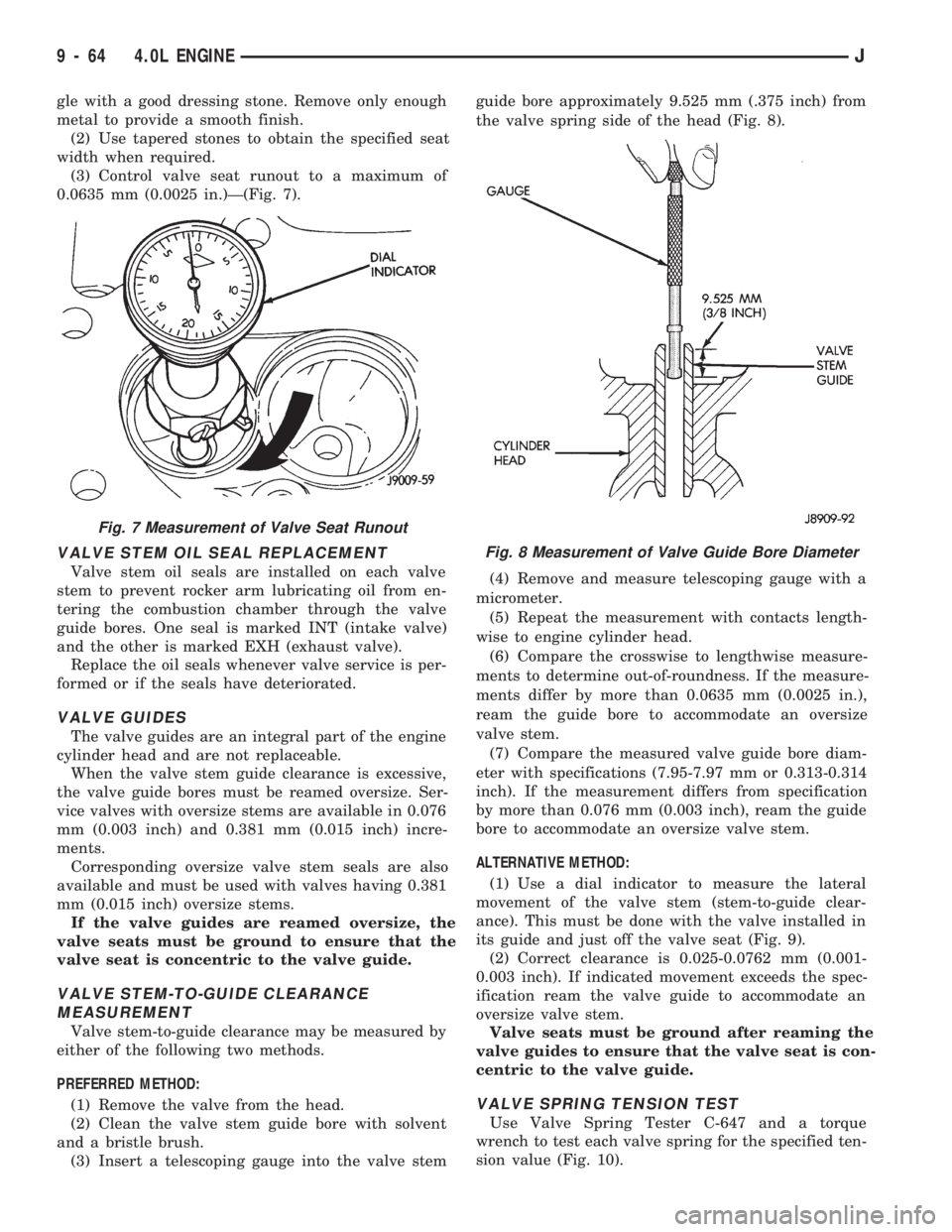
(3) Control valve seat runout to a maximum of
0.0635 mm (0.0025 in.)Ð(Fig. 7).
VALVE STEM OIL SEAL REPLACEMENT
Valve stem oil seals are installed on each valve
stem to prevent rocker arm lubricating oil from en-
tering the combustion chamber through the valve
guide bores. One seal is marked INT (intake valve)
and the other is marked EXH (exhaust valve).
Replace the oil seals whenever valve service is per-
formed or if the seals have deteriorated.
VALVE GUIDES
The valve guides are an integral part of the engine
cylinder head and are not replaceable.
When the valve stem guide clearance is excessive,
the valve guide bores must be reamed oversize. Ser-
vice valves with oversize stems are available in 0.076
mm (0.003 inch) and 0.381 mm (0.015 inch) incre-
ments.
Corresponding oversize valve stem seals are also
available and must be used with valves having 0.381
mm (0.015 inch) oversize stems.
If the valve guides are reamed oversize, the
valve seats must be ground to ensure that the
valve seat is concentric to the valve guide.
VALVE STEM-TO-GUIDE CLEARANCE
MEASUREMENT
Valve stem-to-guide clearance may be measured by
either of the following two methods.
PREFERRED METHOD:
(1) Remove the valve from the head.
(2) Clean the valve stem guide bore with solvent
and a bristle brush.
(3) Insert a telescoping gauge into the valve stemguide bore approximately 9.525 mm (.375 inch) from
the valve spring side of the head (Fig. 8).
(4) Remove and measure telescoping gauge with a
micrometer.
(5) Repeat the measurement with contacts length-
wise to engine cylinder head.
(6) Compare the crosswise to lengthwise measure-
ments to determine out-of-roundness. If the measure-
ments differ by more than 0.0635 mm (0.0025 in.),
ream the guide bore to accommodate an oversize
valve stem.
(7) Compare the measured valve guide bore diam-
eter with specifications (7.95-7.97 mm or 0.313-0.314
inch). If the measurement differs from specification
by more than 0.076 mm (0.003 inch), ream the guide
bore to accommodate an oversize valve stem.
ALTERNATIVE METHOD:
(1) Use a dial indicator to measure the lateral
movement of the valve stem (stem-to-guide clear-
ance). This must be done with the valve installed in
its guide and just off the valve seat (Fig. 9).
(2) Correct clearance is 0.025-0.0762 mm (0.001-
0.003 inch). If indicated movement exceeds the spec-
ification ream the valve guide to accommodate an
oversize valve stem.
Valve seats must be ground after reaming the
valve guides to ensure that the valve seat is con-
centric to the valve guide.
VALVE SPRING TENSION TEST
Use Valve Spring Tester C-647 and a torque
wrench to test each valve spring for the specified ten-
sion value (Fig. 10).
Fig. 7 Measurement of Valve Seat Runout
Fig. 8 Measurement of Valve Guide Bore Diameter
9 - 64 4.0L ENGINEJ
Page 907 of 1784

LEAK-DOWN TEST
After cleaning and inspection, test each tappet for
specified leak-down rate tolerance to ensure zero-lash
operation (Fig. 12).
Swing the weighted arm of the hydraulic valve tap-
pet tester away from the ram of the Leak-Down
Tester 7980.
(1) Place a 7.925-7.950 mm (0.312-0.313 inch) di-
ameter ball bearing on the plunger cap of the tappet.
(2) Lift the ram and position the tappet (with the
ball bearing) inside the tester cup.
(3) Lower the ram, then adjust the nose of the ram
until it contacts the ball bearing. DO NOT tighten
the hex nut on the ram.
(4) Fill the tester cup with hydraulic valve tappet
test oil until the tappet is completely submerged.
(5) Swing the weighted arm onto the push rod and
pump the tappet plunger up and down to remove air.
When the air bubbles cease, swing the weighted arm
away and allow the plunger to rise to the normal po-
sition.
(6) Adjust the nose of the ram to align the pointer
with the SET mark on the scale of the tester and
tighten the hex nut.
(7) Slowly swing the weighted arm onto the push
rod.
(8) Rotate the cup by turning the handle at the
base of the tester clockwise one revolution every 2
seconds.
(9) Observe the leak-down time interval from the
instant the pointer aligns with the START mark on
the scale until the pointer aligns with the 0.125
mark. A normally functioning tappet will require 20-
110 seconds to leak-down. Discard tappets with leak-
down time interval not within this specification.
INSTALLATION
It is not necessary to charge the tappets with en-
gine oil. They will charge themselves within a very
short period of engine operation.(1) Dip each tappet in Mopar Engine Oil Supple-
ment, or equivalent.
(2) Use Hydraulic Valve Tappet Removal/Installa-
tion Tool C-4129-A to install each tappet in the same
bore from where it was originally removed.
(3) Install the exhaust and intake manifolds (refer
to Group 11, Exhaust System and Intake Manifold
for the proper procedure).
(4) Install the engine cylinder head and gasket.
(5) Install the push rods in their original locations.
(6) Install the rocker arms and bridge and pivot
assemblies at their original locations. Loosely install
the capscrews at each bridge.
(7) Tighten the capscrews alternately, one turn at
a time, to avoid damaging the bridges. Tighten the
capscrews to 28 Nzm (21 ft. lbs.) torque.
(8) Pour the remaining Mopar Engine Oil Supple-
ment, or equivalent over the entire valve actuating
assembly. The Mopar Engine Oil Supplement, or
equivalent must remain with the engine oil for at
least 1 609 km (1,000 miles). The oil supplement
need not be drained until the next scheduled oil
change.
(9) Install the engine cylinder head cover.
VALVE TIMING
Disconnect the spark plug wires and remove the
spark plugs.
Remove the engine cylinder head cover.
Remove the capscrews, bridge and pivot assembly,
and rocker arms from above the No.1 cylinder.
Alternately loosen each capscrew, one turn at a
time, to avoid damaging the bridge.
Rotate the crankshaft until the No.6 piston is at
top dead center (TDC) on the compression stroke.
Rotate the crankshaft counterclockwise (viewed
from the front of the engine) 90É.
Install a dial indicator on the end of the No.1 cyl-
inder intake valve push rod. Use rubber tubing to se-
cure the indicator stem on the push rod.
Set the dial indicator pointer at zero.
Rotate the crankshaft clockwise (viewed from the
front of the engine) until the dial indicator pointer
indicates 0.305 mm (0.012 inch) travel distance (lift).
The timing notch index on the vibration damper
should be aligned with the TDC mark on the timing
degree scale.
If the timing notch is more than 13 mm (1/2 inch)
away from the TDC mark in either direction, the
valve timing is incorrect.
If the valve timing is incorrect, the cause may be a
broken camshaft pin. It is not necessary to replace
the camshaft because of pin failure. A spring pin is
available for service replacement.
Fig. 12 Leak-Down Tester 7980
9 - 66 4.0L ENGINEJ
Page 911 of 1784

(5) Remove the distributor cap and mark the posi-
tion of the rotor.
(6) Remove the distributor and ignition wires.
(7) Remove the engine cylinder head cover.
(8) Remove the rocker arms, bridges and pivots.
(9) Remove the push rods.
(10) Remove the engine cylinder head and gasket.
(11) Remove the hydraulic valve tappets from the
engine cylinder head.
(12) Remove the vibration damper.
(13) Remove the timing case cover.
(14) Remove the timing chain and sprockets.
(15) Remove the front bumper and/or grille, as re-
quired.
(16) Remove the camshaft (Fig. 9).
INSPECTION
Inspect the cam lobes for wear.
Inspect the bearing journals for uneven wear pat-
tern or finish.
Inspect the bearings for wear.
Inspect the distributor drive gear for wear.
If the camshaft appears to have been rubbing
against the timing case cover, examine the oil pres-
sure relief holes in the rear cam journal. The oil
pressure relief holes must be free of debris.
INSTALLATION
(1) Lubricate the camshaft with Mopar Engine Oil
Supplement, or equivalent.
(2) Carefully install the camshaft to prevent dam-
age to the camshaft bearings (Fig. 9).
(3) Install the timing chain, crankshaft sprocket
and camshaft sprocket with the timing marks
aligned.
(4) Install the camshaft sprocket retaining preload
bolt. Tighten the bolt to 108 Nzm (80 ft. lbs.) torque.
(5) Lubricate the tension spring, the thrust pin
and the pin bore in the preload bolt with Mopar En-
gine Oil Supplement, or equivalent. Install the
spring and thrust pin in the preload bolt head.(6) Install the timing case cover with a replace-
ment oil seal (Fig. 10). Refer to Timing Case Cover
Installation.
(7) Install the vibration damper (Fig. 10).
(8) Install the hydraulic valve tappets.
(9) Install the engine cylinder head.
(10) Install the push rods.
(11) Install the rocker arms and pivot and bridge
assemblies. Tighten each of the capscrews for each
bridge alternately, one turn at a time, to avoid dam-
aging the bridge.
(12) Install the engine cylinder head cover.
(13) Install the serpentine drive belt and tighten to
the specified tension (refer to Group 7, Cooling Sys-
tem for the proper procedure).
(14) Rotate the crankshaft until the No.1 piston is
at the TDC position on the compression stroke.
(15) Install the distributor, cap and ignition wires.
Install the distributor so that the rotor is aligned
with the mark made during removal. The rotor
should be aligned with the No.1 cylinder spark plug
terminal on the cap when the distributor housing is
fully seated on the cylinder block.
During installation, lubricate the hydraulic
valve tappets and all valve components with Mo-
par Engine Oil Supplement, or equivalent. The
Mopar Engine Oil Supplement, or equivalent
must remain with the engine oil for at least 1 609
km (1,000 miles). The oil supplement need not be
drained until the next scheduled oil change.
(16) Install the A/C condenser and receiver/drier
assembly, if equipped (refer to Group 24, Heating
and Air Conditioning).
CAUTION: Both service valves must be opened be-
fore the air conditioning system is operated.
(17) Install the radiator, connect the hoses and fill
the cooling system to the specified level (refer to
Group 7, Cooling System for the proper procedure).
Fig. 9 Camshaft
Fig. 10 Timing Case Cover Components
9 - 70 4.0L ENGINEJ
Page 915 of 1784
(3) Remove the pump-to-cylinder block attaching
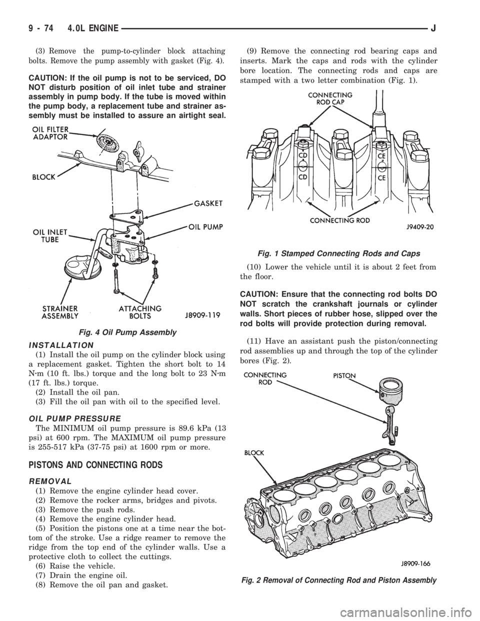
bolts. Remove the pump assembly with gasket (Fig. 4).
CAUTION: If the oil pump is not to be serviced, DO
NOT disturb position of oil inlet tube and strainer
assembly in pump body. If the tube is moved within
the pump body, a replacement tube and strainer as-
sembly must be installed to assure an airtight seal.
INSTALLATION
(1) Install the oil pump on the cylinder block using
a replacement gasket. Tighten the short bolt to 14
Nzm (10 ft. lbs.) torque and the long bolt to 23 Nzm
(17 ft. lbs.) torque.
(2) Install the oil pan.
(3) Fill the oil pan with oil to the specified level.
OIL PUMP PRESSURE
The MINIMUM oil pump pressure is 89.6 kPa (13
psi) at 600 rpm. The MAXIMUM oil pump pressure
is 255-517 kPa (37-75 psi) at 1600 rpm or more.
PISTONS AND CONNECTING RODS
REMOVAL
(1) Remove the engine cylinder head cover.
(2) Remove the rocker arms, bridges and pivots.
(3) Remove the push rods.
(4) Remove the engine cylinder head.
(5) Position the pistons one at a time near the bot-
tom of the stroke. Use a ridge reamer to remove the
ridge from the top end of the cylinder walls. Use a
protective cloth to collect the cuttings.
(6) Raise the vehicle.
(7) Drain the engine oil.
(8) Remove the oil pan and gasket.(9) Remove the connecting rod bearing caps and
inserts. Mark the caps and rods with the cylinder
bore location. The connecting rods and caps are
stamped with a two letter combination (Fig. 1).
(10) Lower the vehicle until it is about 2 feet from
the floor.
CAUTION: Ensure that the connecting rod bolts DO
NOT scratch the crankshaft journals or cylinder
walls. Short pieces of rubber hose, slipped over the
rod bolts will provide protection during removal.
(11) Have an assistant push the piston/connecting
rod assemblies up and through the top of the cylinder
bores (Fig. 2).
Fig. 4 Oil Pump Assembly
Fig. 1 Stamped Connecting Rods and Caps
Fig. 2 Removal of Connecting Rod and Piston Assembly
9 - 74 4.0L ENGINEJ
Page 917 of 1784
journal, bent connecting rod or foreign mate-
rial trapped between the insert and cap or rod.
(8) If the correct clearance is indicated, replace-
ment of the bearing inserts is not necessary. Remove
the Plastigage from crankshaft journal and bearing
insert. Proceed with installation.
(9) If bearing-to-journal clearance exceeds the spec-
ification, install a pair of 0.0254 mm (0.001 inch) un-
dersize bearing inserts. All the odd size inserts must
be on the bottom. The sizes of the service replace-
ment bearing inserts are stamped on the backs of the
inserts. Measure the clearance as described in the
previous steps.
(10) The clearance is measured with a pair of
0.0254 mm (0.001 inch) undersize bearing inserts in-stalled. This will determine if two 0.0254 mm (0.001
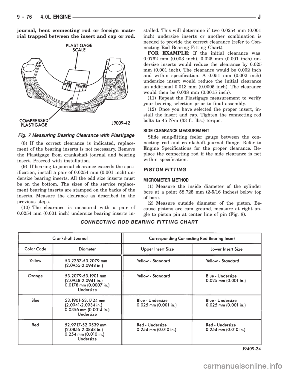
inch) undersize inserts or another combination is
needed to provide the correct clearance (refer to Con-
necting Rod Bearing Fitting Chart).
FOR EXAMPLE:If the initial clearance was
0.0762 mm (0.003 inch), 0.025 mm (0.001 inch) un-
dersize inserts would reduce the clearance by 0.025
mm (0.001 inch). The clearance would be 0.002 inch
and within specification. A 0.051 mm (0.002 inch)
undersize insert would reduce the initial clearance
an additional 0.013 mm (0.0005 inch). The clearance
would then be 0.038 mm (0.0015 inch).
(11) Repeat the Plastigage measurement to verify
your bearing selection prior to final assembly.
(12) Once you have selected the proper insert, in-
stall the insert and cap. Tighten the connecting rod
bolts to 45 Nzm (33 ft. lbs.) torque.
SIDE CLEARANCE MEASUREMENT
Slide snug-fitting feeler gauge between the con-
necting rod and crankshaft journal flange. Refer to
Engine Specifications for the proper clearance. Re-
place the connecting rod if the side clearance is not
within specification.
PISTON FITTING
MICROMETER METHOD
(1) Measure the inside diameter of the cylinder
bore at a point 58.725 mm (2-5/16 inches) below top
of bore.
(2) Measure outside diameter of the piston. Be-
cause pistons are cam ground, measure at right an-
gle to piston pin at center line of pin (Fig. 8).
CONNECTING ROD BEARING FITTING CHART
Fig. 7 Measuring Bearing Clearance with Plastigage
9 - 76 4.0L ENGINEJ
Page 927 of 1784
piston. A slight amount of taper always exists in the
cylinder bore after the engine has been in use for a
period of time.
HONINGÐCYLINDER BORE
The honing operation should be closely coordinated
with the fitting of pistons and rings. This will ensure
specified clearances are maintained.
Refer to Standard Service Procedures in the begin-
ning of this Group for the proper honing of cylinder
bores.
ASSEMBLY
Refer to the applicable sections for detailed instruc-
tions.
(1) Install the crankshaft.
(2) Install the connecting rods and the pistons
through the top of the cylinder bores.(3) Install the oil pump.
(4) Install the oil pan and gasket.
(5) Install the camshaft.
(6) Install the sprockets and chain as an assembly.
(7) Install the oil slinger from the crankshaft.
(8) Install the timing case cover seal.
(9) Install the timing case cover.
(10) Install the vibration damper.
(11) Install the water pump. Tighten the mounting
bolts to 31 Nzm (270 in. lbs.) torque.
(12) Lubricate the oil filter seal with clean engine
oil. Tighten oil filter to 18 Nzm (13 ft. lbs.) torque.
(13) Install the engine into the vehicle.
(14) Fill the engine with clean lubrication oil (re-
fer to Group 0, Lubrication and Maintenance).
(15) Fill the cooling system (refer to Group 7, Cool-
ing System for the proper procedures).
9 - 86 4.0L ENGINEJ