1994 JEEP CHEROKEE service
[x] Cancel search: servicePage 463 of 1784
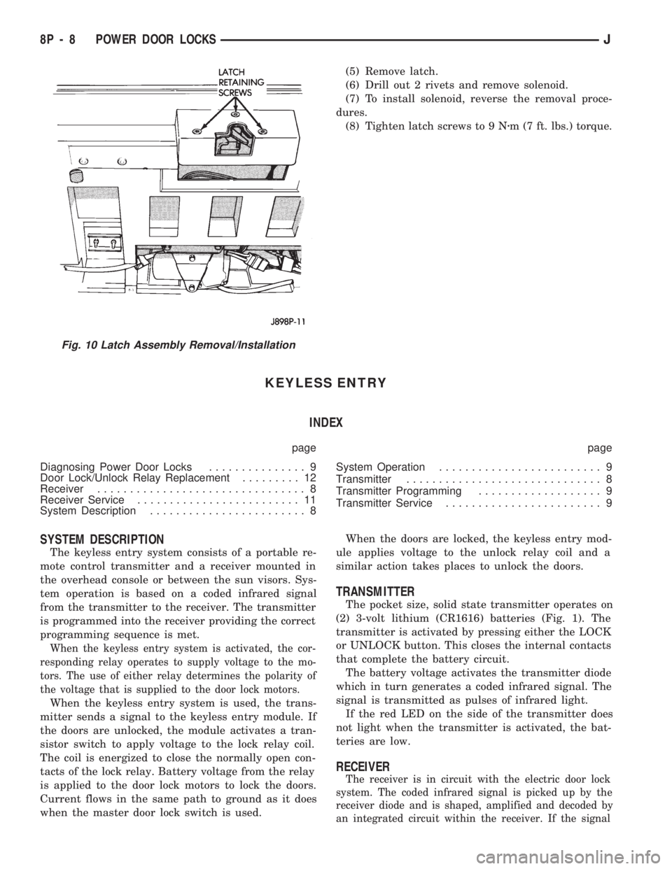
(5) Remove latch.
(6) Drill out 2 rivets and remove solenoid.
(7) To install solenoid, reverse the removal proce-
dures.
(8) Tighten latch screws to 9 Nzm (7 ft. lbs.) torque.
KEYLESS ENTRY
INDEX
page page
Diagnosing Power Door Locks............... 9
Door Lock/Unlock Relay Replacement......... 12
Receiver................................ 8
Receiver Service......................... 11
System Description........................ 8System Operation......................... 9
Transmitter.............................. 8
Transmitter Programming................... 9
Transmitter Service........................ 9
SYSTEM DESCRIPTION
The keyless entry system consists of a portable re-
mote control transmitter and a receiver mounted in
the overhead console or between the sun visors. Sys-
tem operation is based on a coded infrared signal
from the transmitter to the receiver. The transmitter
is programmed into the receiver providing the correct
programming sequence is met.
When the keyless entry system is activated, the cor-
responding relay operates to supply voltage to the mo-
tors. The use of either relay determines the polarity of
the voltage that is supplied to the door lock motors.
When the keyless entry system is used, the trans-
mitter sends a signal to the keyless entry module. If
the doors are unlocked, the module activates a tran-
sistor switch to apply voltage to the lock relay coil.
The coil is energized to close the normally open con-
tacts of the lock relay. Battery voltage from the relay
is applied to the door lock motors to lock the doors.
Current flows in the same path to ground as it does
when the master door lock switch is used.When the doors are locked, the keyless entry mod-
ule applies voltage to the unlock relay coil and a
similar action takes places to unlock the doors.
TRANSMITTER
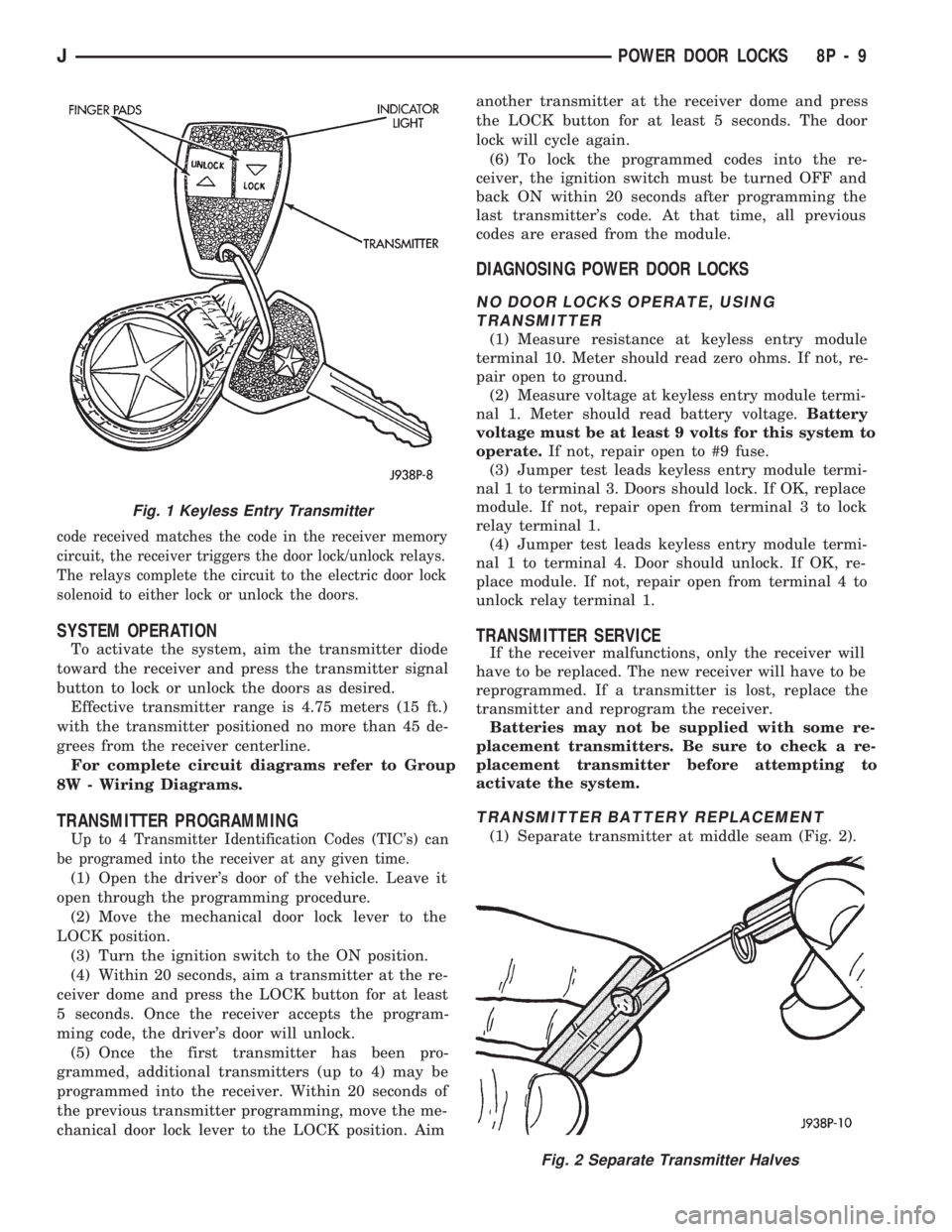
The pocket size, solid state transmitter operates on
(2) 3-volt lithium (CR1616) batteries (Fig. 1). The
transmitter is activated by pressing either the LOCK
or UNLOCK button. This closes the internal contacts
that complete the battery circuit.
The battery voltage activates the transmitter diode
which in turn generates a coded infrared signal. The
signal is transmitted as pulses of infrared light.
If the red LED on the side of the transmitter does
not light when the transmitter is activated, the bat-
teries are low.
RECEIVER
The receiver is in circuit with the electric door lock
system. The coded infrared signal is picked up by the
receiver diode and is shaped, amplified and decoded by
an integrated circuit within the receiver. If the signal
Fig. 10 Latch Assembly Removal/Installation
8P - 8 POWER DOOR LOCKSJ
Page 464 of 1784
code received matches the code in the receiver memory
circuit, the receiver triggers the door lock/unlock relays.
The relays complete the circuit to the electric door lock
solenoid to either lock or unlock the doors.
SYSTEM OPERATION
To activate the system, aim the transmitter diode
toward the receiver and press the transmitter signal
button to lock or unlock the doors as desired.
Effective transmitter range is 4.75 meters (15 ft.)
with the transmitter positioned no more than 45 de-
grees from the receiver centerline.
For complete circuit diagrams refer to Group
8W - Wiring Diagrams.
TRANSMITTER PROGRAMMING
Up to 4 Transmitter Identification Codes (TIC's) can
be programed into the receiver at any given time.
(1) Open the driver's door of the vehicle. Leave it
open through the programming procedure.
(2) Move the mechanical door lock lever to the
LOCK position.
(3) Turn the ignition switch to the ON position.
(4) Within 20 seconds, aim a transmitter at the re-
ceiver dome and press the LOCK button for at least
5 seconds. Once the receiver accepts the program-
ming code, the driver's door will unlock.
(5) Once the first transmitter has been pro-
grammed, additional transmitters (up to 4) may be
programmed into the receiver. Within 20 seconds of
the previous transmitter programming, move the me-
chanical door lock lever to the LOCK position. Aimanother transmitter at the receiver dome and press
the LOCK button for at least 5 seconds. The door
lock will cycle again.
(6) To lock the programmed codes into the re-
ceiver, the ignition switch must be turned OFF and
back ON within 20 seconds after programming the
last transmitter's code. At that time, all previous
codes are erased from the module.
DIAGNOSING POWER DOOR LOCKS
NO DOOR LOCKS OPERATE, USING
TRANSMITTER
(1) Measure resistance at keyless entry module
terminal 10. Meter should read zero ohms. If not, re-
pair open to ground.
(2) Measure voltage at keyless entry module termi-
nal 1. Meter should read battery voltage.Battery
voltage must be at least 9 volts for this system to
operate.If not, repair open to #9 fuse.
(3) Jumper test leads keyless entry module termi-
nal 1 to terminal 3. Doors should lock. If OK, replace
module. If not, repair open from terminal 3 to lock
relay terminal 1.
(4) Jumper test leads keyless entry module termi-
nal 1 to terminal 4. Door should unlock. If OK, re-
place module. If not, repair open from terminal 4 to
unlock relay terminal 1.
TRANSMITTER SERVICE
If the receiver malfunctions, only the receiver will
have to be replaced. The new receiver will have to be
reprogrammed. If a transmitter is lost, replace the
transmitter and reprogram the receiver.
Batteries may not be supplied with some re-
placement transmitters. Be sure to check a re-
placement transmitter before attempting to
activate the system.
TRANSMITTER BATTERY REPLACEMENT
(1) Separate transmitter at middle seam (Fig. 2).
Fig. 2 Separate Transmitter Halves
Fig. 1 Keyless Entry Transmitter
JPOWER DOOR LOCKS 8P - 9
Page 466 of 1784
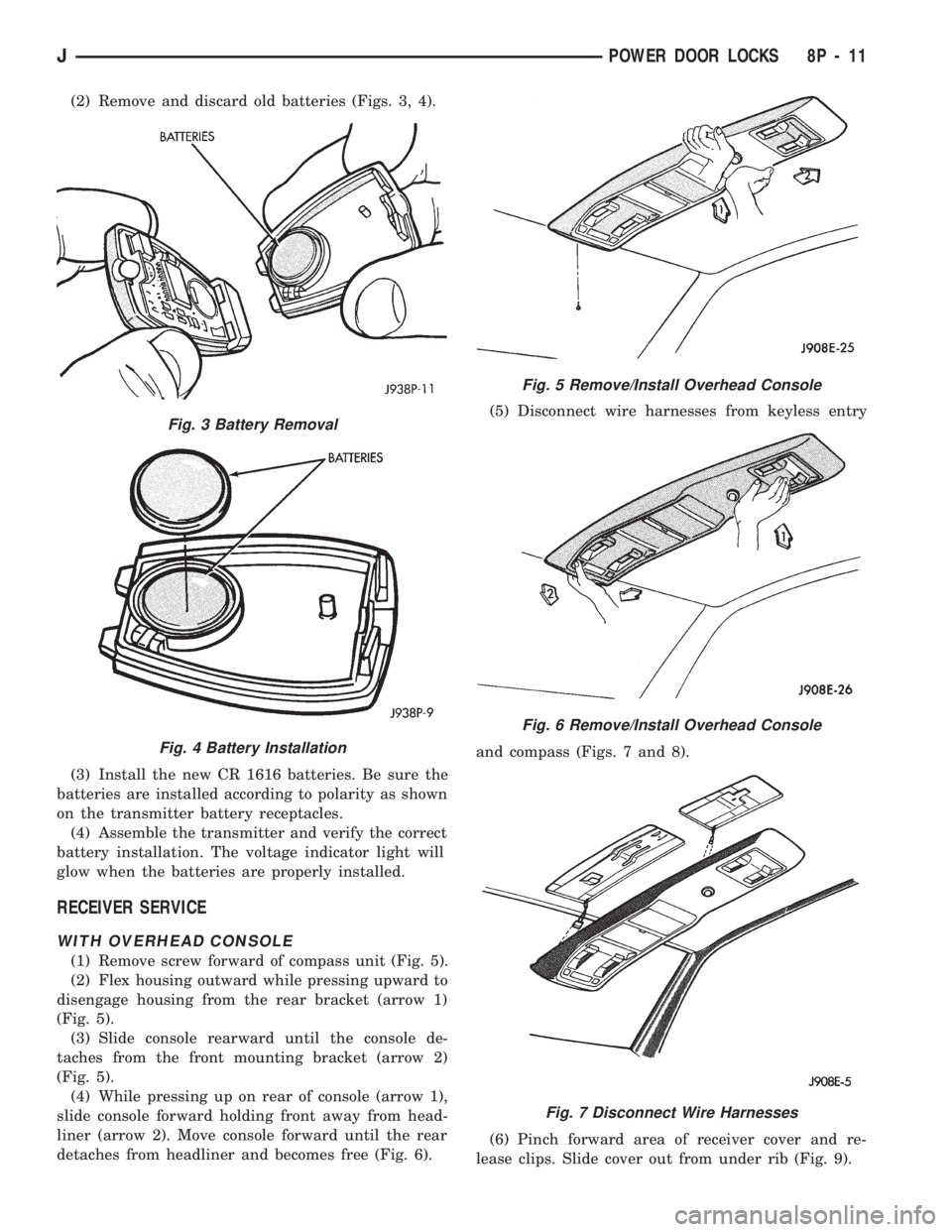
(2) Remove and discard old batteries (Figs. 3, 4).
(3) Install the new CR 1616 batteries. Be sure the
batteries are installed according to polarity as shown
on the transmitter battery receptacles.
(4) Assemble the transmitter and verify the correct
battery installation. The voltage indicator light will
glow when the batteries are properly installed.
RECEIVER SERVICE
WITH OVERHEAD CONSOLE
(1) Remove screw forward of compass unit (Fig. 5).
(2) Flex housing outward while pressing upward to
disengage housing from the rear bracket (arrow 1)
(Fig. 5).
(3) Slide console rearward until the console de-
taches from the front mounting bracket (arrow 2)
(Fig. 5).
(4) While pressing up on rear of console (arrow 1),
slide console forward holding front away from head-
liner (arrow 2). Move console forward until the rear
detaches from headliner and becomes free (Fig. 6).(5) Disconnect wire harnesses from keyless entry
and compass (Figs. 7 and 8).
(6) Pinch forward area of receiver cover and re-
lease clips. Slide cover out from under rib (Fig. 9).
Fig. 3 Battery Removal
Fig. 4 Battery Installation
Fig. 5 Remove/Install Overhead Console
Fig. 6 Remove/Install Overhead Console
Fig. 7 Disconnect Wire Harnesses
JPOWER DOOR LOCKS 8P - 11
Page 494 of 1784

WIRING DIAGRAMS
CONTENTS
page page
FUSE CHARTS AND RELAY BANKS......... 8
GENERAL INFORMATION.................. 1
SPLICE LOCATIONS..................... 53
WIRING AND COMPONENT IDENTIFICATION . 13WIRING DIAGRAMS XJ.................. 149
WIRING DIAGRAMS XJ RHD............. 271
WIRING DIAGRAMS YJ.................. 73
GENERAL INFORMATION
INDEX
page page
Circuit Identification........................ 2
Component Identification.................... 2
Connector and Terminal Assembly Replacement . . 5
Connector Replacement.................... 4
Connectors.............................. 3
Fusible Link Replacement................... 4
Fusible Links............................. 3
Locating A System........................ 2Secondary Ignition Wiring................... 1
Splice Locations.......................... 2
Symbols, Fuses and Abbreviations............ 6
Terminal Replacement...................... 5
Troubleshooting Wiring Problems.............. 3
Wire Code Identification.................... 2
Wiring Diagram Sheets and Indexes........... 1
Wiring Repair............................ 4
The wiring diagrams contain the latest information
at the time of publication.
Throughout this group references may be made to
a particular vehicle by letter or number designation.
A chart showing the breakdown of these designations
is included in the Introduction Section at the front of
this service manual.
SECONDARY IGNITION WIRING
Secondary ignition wiring is shown in Figures 1
and 2. For additional information on ignition systems
or distributor operation refer to Group 8D Ignition
Systems.
WIRING DIAGRAM SHEETS AND INDEXES
The diagrams are organized to show the basic ve-
hicle and all of its options. Add-on or non-factory op-
tions are not covered. The diagram pages are
identified by a sheet number which is located at the
lower right or left hand corner of each sheet.Page
numbers at the top of each page do not apply to
diagram sheets.
Diagram sheets show all information relating to
the system. This includes feeds, grounds, switch in-
ternal circuity, connectors, splices, and pin identifica-
tion for controllers and modules. All components,switches, and relays are shown in the at rest position
with the key removed from the ignition and the doors
closed.
In certain instances a wire may be referenced to
another sheet. When this happens, the wire will be
identified as to where it is going.
The index used for the diagrams is located at the
beginning of the section. The main system and all re-
lated components are covered.
Fig. 1 Secondary Ignition Wiring 2.5L
JWIRING DIAGRAMS 8W - 1
Page 842 of 1784
ENGINES
CONTENTS
page page
2.5L ENGINE SERVICE PROCEDURES....... 9
4.0L ENGINE SERVICE PROCEDURES...... 50ENGINE DIAGNOSIS...................... 5
STANDARD SERVICE PROCEDURES......... 1
STANDARD SERVICE PROCEDURES
INDEX
page page
Engine Performance....................... 2
Form-In-Place Gaskets..................... 1
Honing Cylinder Bores..................... 2
Hydrostatic Lock.......................... 4Measuring with Plastigage................... 3
Repair Damaged or Worn Threads............ 4
Service Engine Assembly (Short Block)......... 4
FORM-IN-PLACE GASKETS
There are several places where form-in-place gas-
kets are used on the engine.DO NOT use form-in-
place gasket material unless specified.Care must
be taken when applying form-in-place gaskets. Bead
size, continuity and location are of great importance.
Too thin a bead can result in leakage while too much
can result in spill-over. A continuous bead of the
proper width is essential to obtain a leak-free joint.
Two types of form-in-place gasket materials are
used in the engine area (Mopar Silicone Rubber Ad-
hesive Sealant and Mopar Gasket Maker). Each have
different properties and cannot be used interchange-
ably.
MOPAR SILICONE RUBBER ADHESIVE
SEALANT
Mopar Silicone Rubber Adhesive Sealant, normally
black in color, is available in 3 ounce tubes. Moisture
in the air causes the sealant material to cure. This
material is normally used on flexible metal flanges.
It has a shelf life of a year and will not properly cure
if over aged. Always inspect the package for the ex-
piration date before use.
MOPAR GASKET MAKER
Mopar Gasket Maker, normally red in color, is
available in 6 cc tubes. This anaerobic type gasket
material cures in the absence of air when squeezed
between smooth machined metallic surfaces. It will
not cure if left in the uncovered tube. DO NOT use
on flexible metal flanges.
SURFACE PREPARATION
Parts assembled with form-in-place gaskets may be
disassembled without unusual effort. In some in-
stances, it may be necessary to lightly tap the part
with a mallet or other suitable tool to break the seal
between the mating surfaces. A flat gasket scraper
may also be lightly tapped into the joint but care
must be taken not to damage the mating surfaces.
Scrape or wire brush all gasket surfaces to remove
all loose material. Inspect stamped parts to ensure
gasket rails are flat. Flatten rails with a hammer on
a flat plate, if required. Gasket surfaces must be free
of oil and dirt. Make sure the old gasket material is
removed from blind attaching holes.
GASKET APPLICATION
Assembling parts using a form-in-place gasket re-
quires care.
Mopar Silicone Rubber Adhesive Sealant should be
applied in a continuous bead approximately 3 mm
(0.12 inch) in diameter. All mounting holes must be
circled. For corner sealing,a3or6mm(1/8 or 1/4
inch) drop is placed in the center of the gasket con-
tact area. Uncured sealant may be removed with a
shop towel. Components should be torqued in place
while the sealant is still wet to the touch (within 10
minutes). The use of a locating dowel is recom-
mended during assembly to prevent smearing the
material off location.
Mopar Gasket Maker should be applied sparingly
to one gasket surface. The sealant diameter should
be 1.00 mm (0.04 inch) or less. Be certain the mate-
rial surrounds each mounting hole. Excess material
JENGINES 9 - 1
Page 843 of 1784

can easily be wiped off. Components should be
torqued in place within 15 minutes. The use of a lo-
cating dowel is recommended during assembly to pre-
vent smearing the material off location.
ENGINE PERFORMANCE
To provide best vehicle performance and lowest ve-
hicle emissions, it is most important that the tune-up
be done accurately. Use the specifications listed on
the Vehicle Emission Control Information label
found on the engine compartment hood.
(1) Test battery specific gravity. Add water, if nec-
essary. Clean and tighten battery connections.
(2) Test cranking amperage draw (refer to Group
8B, Battery/Starter Service for the proper proce-
dures).
(3) Tighten the intake manifold bolts (refer to
Group 11, Exhaust System and Intake Manifold for
the proper specifications).
(4) Perform cylinder compression test:
(a) Check engine oil level and add oil, if neces-
sary.
(b) Drive the vehicle until engine reaches normal
operating temperature.
(c) Select a route free from traffic and other
forms of congestion, observe all traffic laws and
briskly accelerate through the gears several times.
The higher engine speed may help clean out valve
seat deposits which can prevent accurate compres-
sion readings.
CAUTION: DO NOT overspeed the engine.
(d) Remove all spark plugs from engine. As
spark plugs are being removed, check electrodes for
abnormal firing indicators - fouled, hot, oily, etc.
Record cylinder number of spark plug for future
reference.
(e) Disconnect coil wire from distributor and se-
cure to good ground to prevent a spark from start-
ing a fire.
(f) Be sure throttle blades are fully open during
the compression check.
(g) Insert compression gage adaptor into the
No.1 spark plug hole. Crank engine until maxi-
mum pressure is reached on gauge. Record this
pressure as No.1 cylinder pressure.
(h) Repeat Step 4g for all remaining cylinders.
(i) Compression should not be less than 689 kPa
(100 psi) and not vary more than 172 kPa (25 psi)
from cylinder to cylinder.
(j) If cylinder(s) have abnormally low compres-
sion pressures, repeat steps 4a through 4h.
(k) If the same cylinder(s) repeat an abnormally
low reading, it could indicate the existence of a
problem in the cylinder.
The recommended compression pressures are
to be used only as a guide to diagnosing engineproblems. An engine should NOT be disassem-
bled to determine the cause of low compression
unless some malfunction is present.
(5) Clean or replace spark plugs as necessary. Ad-
just gap (refer to Group 8D, Ignition System for gap
adjustment and torque).
(6) Test resistance of spark plug cables (refer to
Group 8D, Ignition System).
(7) Inspect the primary wire. Test coil output volt-
age, primary and secondary resistance. Replace parts
as necessary (refer to Group 8D, Ignition System and
make necessary adjustment).
(8) Set ignition timing to specifications (refer to
Specification Label on engine compartment hood).
(9) Perform a combustion analysis.
(10) Test fuel pump for pressure and vacuum (refer
to Group 14, Fuel System for the proper specifica-
tions).
(11) Inspect air filter element (refer to Group 0,
Lubrication and Maintenance for the proper proce-
dure).
(12) Inspect crankcase ventilation system (refer to
Group 0, Lubrication and Maintenance for the proper
procedure).
(13) For emission controls refer to Group 25, Emis-
sion Controls System for service procedures.
(14) Inspect and adjust accessory belt drives (refer
to Group 7, Cooling System for the proper adjust-
ments).
(15) Road test vehicle as a final test.
HONING CYLINDER BORES
Before honing, stuff plenty of clean shop towels un-
der the bores and over the crankshaft to keep abra-
sive materials from entering the crankshaft area.
(1) Used carefully, the Cylinder Bore Sizing Hone
C-823 equipped with 220 grit stones, is the best tool
for this job. In addition to deglazing, it will reduce
taper and out-of-round as well as removing light
scuffing, scoring or scratches. Usually a few strokes
will clean up a bore and maintain the required lim-
its.
CAUTION: DO NOT use rigid type hones to remove
cylinder wall glaze.
(2) Deglazing of the cylinder walls may be done if
the cylinder bore is straight and round. Use a cylin-
der surfacing hone, Honing Tool C-3501, equipped
with 280 grit stones (C-3501-3810). 20-60 strokes, de-
pending on the bore condition, will be sufficient to
provide a satisfactory surface. Using honing oil
C-3501-3880 or a light honing oil available from ma-
jor oil distributors.
CAUTION: DO NOT use engine or transmission oil,
mineral spirits or kerosene.
9 - 2 ENGINESJ
Page 845 of 1784

CONNECTING ROD BEARING CLEARANCE
Engine connecting rod bearing clearances can be
determined by use of Plastigage, or equivalent. The
following is the recommended procedures for the use
of Plastigage:
(1) Remove oil film from surface to be checked.
Plastigage is soluble in oil.
(2) Place a piece of Plastigage across the entire
width of the bearing cap shell (Fig. 2). Position the
Plastigage approximately 6.35 mm (1/4 inch) off cen-
ter and away from the oil holes. In addition, suspect
areas can be checked by placing the Plastigage in the
suspect area.
(3) The crankshaft must be turned until the con-
necting rod to be checked starts moving toward the
top of the engine. Only then should the rod cap with
Plastigage in place be assembled. Tighten the rod
cap nut to 45 Nzm (33 ft. lbs.) torque.DO NOT ro-
tate the crankshaft or the Plastigage may be
smeared, giving inaccurate results.
(4) Remove the bearing cap and compare the width
of the flattened Plastigage with the scale provided on
the package (Fig. 3). Plastigage generally comes in 2
scales (one scale is in inches and the other is a met-
ric scale). Locate the band closest to the same width.
This band shows the amount of clearance. Differ-
ences in readings between the ends indicate the
amount of taper present. Record all readings taken
(refer to Engine Specifications).
(5) Plastigage is available in a variety of clearance
ranges. The 0.025-0.076 mm (0.001-0.003 inch) range
is usually the most appropriate for checking engine
bearing clearances.
REPAIR DAMAGED OR WORN THREADS
Damaged or worn threads can be repaired. Essen-
tially, this repair consists of:
²Drilling out worn or damaged threads.
²Tapping the hole with a special Heli-Coil Tap, or
equivalent.
²Installing an insert into the tapped hole.
This brings the hole back to its original thread size.
CAUTION: Be sure that the tapped holes maintain
the original center line.Heli-Coil tools and inserts are readily available
from automotive parts jobbers.
SERVICE ENGINE ASSEMBLY (SHORT BLOCK)
A service replacement engine assembly (short
block) may be installed whenever the original cylin-
der block is defective or damaged beyond repair. It
consists of the cylinder block, crankshaft, piston and
rod assemblies. If needed, the camshaft must be pro-
cured separately and installed before the engine is
installed in the vehicle.
A short block is identified with the letter ``S'' stamped
on the same machined surface where the build date
code is stamped for complete engine assemblies.
Installation includes the transfer of components
from the defective or damaged original engine. Fol-
low the appropriate procedures for cleaning, inspec-
tion and torque tightening.
HYDROSTATIC LOCK
When an engine is suspected of hydrostatic lock
(regardless of what caused the problem), follow the
steps below.
(1) Perform the Fuel Pressure Release Procedure
(refer to Group 14, Fuel System).
(2) Disconnect the negative cable from the battery.
(3) Inspect air cleaner, induction system and in-
take manifold to ensure system is dry and clear of
foreign material.
(4) Place a shop towel around the spark plugs to
catch any fluid that may possibly be under pressure in
the cylinder head. Remove the plugs from the engine.
CAUTION: DO NOT use the starter motor to rotate
the crankshaft. Severe damage could occur.
(5) With all spark plugs removed, rotate the crank-
shaft using a breaker bar and socket.
(6) Identify the fluid in the cylinders (i.e. coolant,
fuel, oil, etc.).
(7) Make sure all fluid has been removed from the
cylinders.
(8) Repair engine or components as necessary to
prevent this problem from occurring again.
(9) Squirt engine oil into the cylinders to lubricate
the walls. This will prevent damage on restart.
(10) Install new spark plugs. Tighten the spark
plugs to 37 Nzm (27 ft. lbs.) torque.
(11) Drain engine oil. Remove and discard the oil
filter.
(12) Install the drain plug. Tighten the plug to 34
Nzm (25 ft. lbs.) torque.
(13) Install a new oil filter.
(14) Fill engine crankcase with the specified
amount and grade of oil (refer to Group 0, Lubrica-
tion and Maintenance).
(15) Connect the negative cable to the battery.
(16) Start the engine and check for any leaks.
Fig. 3 Clearance Measurement
9 - 4 ENGINESJ
Page 846 of 1784
ENGINE DIAGNOSIS
Engine diagnosis is helpful in determining the
causes of malfunctions not detected and remedied by
routine tune-ups.
These malfunctions may be classified as either per-
formance (e.g., engine idles rough and stalls) or me-
chanical (e.g., a strange noise).
Refer to the Service DiagnosisÐPerformance chart
and the Service DiagnosisÐMechanical chart for pos-
sible causes and corrections of malfunctions. Refer to
Group 14, Fuel System for the fuel system diagnosis.
Additional tests and diagnostic procedures may be
necessary for specific engine malfunctions that can
not be isolated with the Service Diagnosis charts. In-
formation concerning additional tests and diagnosis
is provided within the following diagnosis:
²Cylinder Compression Pressure Test.
²Cylinder Combustion Pressure Leakage Test.
²Engine Cylinder Head Gasket Failure Diagnosis.
²Intake Manifold Leakage Diagnosis.
INTAKE MANIFOLD LEAKAGE DIAGNOSIS
An intake manifold air leak is characterized by
lower than normal manifold vacuum. Also, one or
more cylinders may not be functioning.
WARNING: USE EXTREME CAUTION WHEN THE
ENGINE IS OPERATING. DO NOT STAND IN A DI-
RECT LINE WITH THE FAN. DO NOT PUT YOUR
HANDS NEAR THE PULLEYS, BELTS OR THE FAN.
DO NOT WEAR LOOSE CLOTHING.
METHOD 1
(1) Start the engine.
(2) Open the acetylene valve of an oxyacetylene
torch. DO NOT ignite.
(3) Pass the torch tip over the exposed gasket area
(EDGE) between the manifold and the engine cylin-
der head.
(4) If the engine speed increases, the manifold has
an air leak.
METHOD 2
(1) Start the engine.
(2) Apply engine oil to the exposed gasket area
(EDGE) between the manifold and the engine cylin-
der head.
(3) If oil is forced into the manifold and if smoke is
visible from the exhaust tailpipe, the manifold has
an air leak.
CYLINDER COMPRESSION PRESSURE TEST
The results of a cylinder compression pressure test
can be utilized to diagnose several engine malfunc-
tions.
Ensure the battery is completely charged and the
engine starter motor is in good operating condition.Otherwise the indicated compression pressures may
not be valid for diagnosis purposes.
(1) Clean the spark plug recesses with compressed
air.
(2) Remove the spark plugs.
(3) Secure the throttle in the wide-open position.
(4) Disconnect the ignition coil.
(5) Insert a compression pressure gauge and rotate
the engine with the engine starter motor for three
revolutions.
(6) Record the compression pressure on the 3rd
revolution. Continue the test for the remaining cyl-
inders.
Refer to Engine Specifications for the correct en-
gine compression pressures.
ENGINE CYLINDER HEAD GASKET FAILURE
DIAGNOSIS
A leaking engine cylinder head gasket usually re-
sults in loss of power, loss of coolant and engine mis-
firing.
An engine cylinder head gasket leak can be located
between adjacent cylinders or between a cylinder and
the adjacent water jacket.
²An engine cylinder head gasket leaking between
adjacent cylinders is indicated by a loss of power
and/or engine misfire.
²An engine cylinder head gasket leaking between a
cylinder and an adjacent water jacket is indicated by
coolant foaming or overheating and loss of coolant.
CYLINDER-TO-CYLINDER LEAKAGE TEST
To determine if an engine cylinder head gasket is
leaking between adjacent cylinders; follow the proce-
dures outlined in Cylinder Compression Pressure
Test. An engine cylinder head gasket leaking be-
tween adjacent cylinders will result in approximately
a 50-70% reduction in compression pressure.
CYLINDER-TO-WATER JACKET LEAKAGE
TEST
WARNING: USE EXTREME CAUTION WHEN THE
ENGINE IS OPERATING. DO NOT STAND IN A DI-
RECT LINE WITH THE FAN. DO NOT PUT YOUR
HANDS NEAR THE PULLEYS, BELTS OR THE FAN.
DO NOT WEAR LOOSE CLOTHING.
Remove the radiator cap.
Start the engine and allow it to warm up until the
engine thermostat opens.
If a large combustion/compression pressure leak ex-
ists, bubbles will be visible in the coolant.
If bubbles are not visible, install a radiator pres-
sure tester and pressurize the coolant system.
JENGINES 9 - 5