1994 JEEP CHEROKEE service
[x] Cancel search: servicePage 341 of 1784

INSTALLATION
(1) Install MAP sensor to dash panel and secure
with mounting nuts.
(2) Install the MAP sensor vacuum supply hose.
(3) Connect the MAP sensor electrical connector.
OXYGEN (O2S) SENSOR
For diagnostics and removal/installation proce-
dures, refer to Group 14, Fuel Systems, in this man-
ual.
POWERTRAIN CONTROL MODULE (PCM)
The PCM was formerly referred to as the SBEC or
engine controller.
XJ MODELS
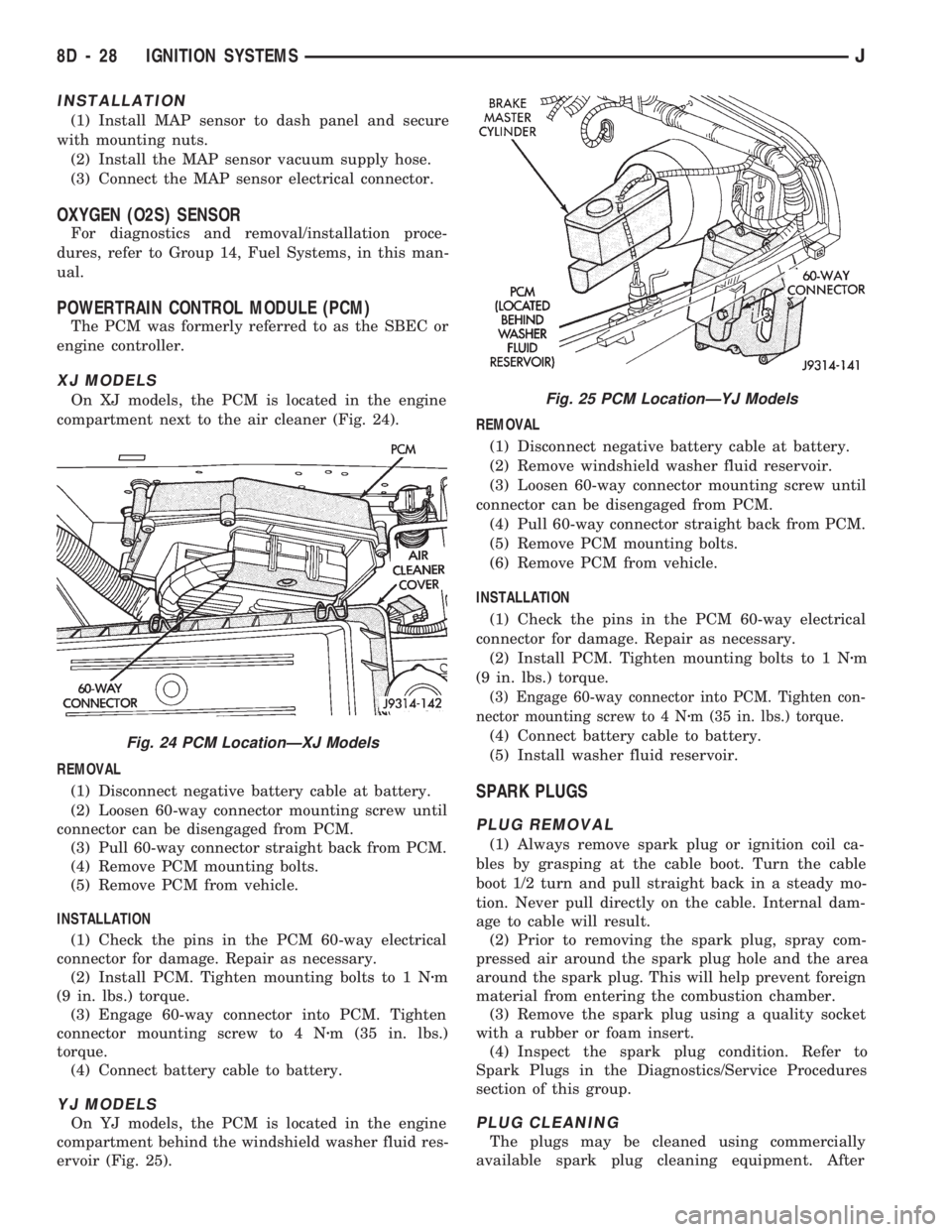
On XJ models, the PCM is located in the engine
compartment next to the air cleaner (Fig. 24).
REMOVAL
(1) Disconnect negative battery cable at battery.
(2) Loosen 60-way connector mounting screw until
connector can be disengaged from PCM.
(3) Pull 60-way connector straight back from PCM.
(4) Remove PCM mounting bolts.
(5) Remove PCM from vehicle.
INSTALLATION
(1) Check the pins in the PCM 60-way electrical
connector for damage. Repair as necessary.
(2) Install PCM. Tighten mounting bolts to 1 Nzm
(9 in. lbs.) torque.
(3) Engage 60-way connector into PCM. Tighten
connector mounting screw to 4 Nzm (35 in. lbs.)
torque.
(4) Connect battery cable to battery.
YJ MODELS
On YJ models, the PCM is located in the engine
compartment behind the windshield washer fluid res-
ervoir (Fig. 25).REMOVAL
(1) Disconnect negative battery cable at battery.
(2) Remove windshield washer fluid reservoir.
(3) Loosen 60-way connector mounting screw until
connector can be disengaged from PCM.
(4) Pull 60-way connector straight back from PCM.
(5) Remove PCM mounting bolts.
(6) Remove PCM from vehicle.
INSTALLATION
(1) Check the pins in the PCM 60-way electrical
connector for damage. Repair as necessary.
(2) Install PCM. Tighten mounting bolts to 1 Nzm
(9 in. lbs.) torque.
(3) Engage 60-way connector into PCM. Tighten con-
nector mounting screw to 4 Nzm (35 in. lbs.) torque.
(4) Connect battery cable to battery.
(5) Install washer fluid reservoir.
SPARK PLUGS
PLUG REMOVAL
(1) Always remove spark plug or ignition coil ca-
bles by grasping at the cable boot. Turn the cable
boot 1/2 turn and pull straight back in a steady mo-
tion. Never pull directly on the cable. Internal dam-
age to cable will result.
(2) Prior to removing the spark plug, spray com-
pressed air around the spark plug hole and the area
around the spark plug. This will help prevent foreign
material from entering the combustion chamber.
(3) Remove the spark plug using a quality socket
with a rubber or foam insert.
(4) Inspect the spark plug condition. Refer to
Spark Plugs in the Diagnostics/Service Procedures
section of this group.
PLUG CLEANING
The plugs may be cleaned using commercially
available spark plug cleaning equipment. After
Fig. 24 PCM LocationÐXJ Models
Fig. 25 PCM LocationÐYJ Models
8D - 28 IGNITION SYSTEMSJ
Page 348 of 1784

INSTRUMENT PANEL AND GAUGES
GROUP INDEX
page page
INSTRUMENT PANEL AND GAUGESÐXJ..... 1INSTRUMENT PANEL AND GAUGESÐYJ.... 14
INSTRUMENT PANEL AND GAUGESÐXJE
CONTENTS
page page
INSTRUMENT CLUSTER DIAGNOSIS........ 3
INSTRUMENT CLUSTER GENERAL INFORMATION.. 1
INSTRUMENT CLUSTER SERVICE PROCEDURES... 5
SPECIFICATIONS....................... 13
INSTRUMENT CLUSTER GENERAL INFORMATION
INDEX
page page
4WD Indicator Lamp........................ 2
Anti-Lock Brake Indicator Lamp............... 2
Brake Indicator Lamp....................... 2
Coolant Temperature Gauge................. 1
Coolant Temperature Indicator Lamp........... 1
Fuel Gauge.............................. 2
Low Fuel Warning Lamp..................... 2Malfunction Indicator Lamp (Check Engine)...... 2
Oil Pressure Gauge....................... 1
Oil Pressure Indicator Lamp.................. 1
Speedometer/Odometer System.............. 2
Tachometer.............................. 2
Upshift Indicator Lamp...................... 2
Voltmeter............................... 1
With the ignition switch in the ON or START posi-
tion, voltage supplied to the instrument cluster is lim-
ited by fuse #17. The voltage is supplied to all the
gauges and indicator lamps through the instrument
cluster printed circuit.
With the ignition switch in the OFF position, volt-
age is not supplied to the instrument cluster and the
gauges do not indicate any vehicle condition.
VOLTMETER
The voltmeter measures battery or generator out-
put voltage, whichever is greater.
OIL PRESSURE GAUGE
The oil pressure gauge pointer position is controlled
by a magnetic field created by electrical current flow
through the coils within the gauge. A change in current
flow will change the magnetic field which changes the
pointer position. The oil pressure sender is a variable
resistor that changes electrical resistance with a change
in oil pressure (values shown in Specifications chart).
OIL PRESSURE INDICATOR LAMP
Voltage is supplied to one side of the indicator bulb
and the oil pressure switch is connected to the other
side. When oil pressure is too low the switch closes
providing a path to ground, and the indicator bulb
lights.
COOLANT TEMPERATURE GAUGE
The coolant temperature gauge pointer position is
controlled by a magnetic field created by electrical
current flow through the coils within the gauge. A
change in current flow will change the magnetic field
which changes the pointer position. The coolant tem-
perature sensor is a thermistor that changes electri-
cal resistance with a change in coolant temperature
(values shown in Specifications chart).
COOLANT TEMPERATURE INDICATOR LAMP
Voltage is supplied to one side of the indicator bulb
and the coolant temperature switch is connected to the
JINSTRUMENT PANEL AND GAUGES 8E - 1
Page 349 of 1784

other side. When coolant temperature is too high the
switch closes providing a path to ground, and the indi-
cator bulb lights.
TACHOMETER
The tachometer displays the engine speed (RPM).
With the engine running, the tachometer receives an
engine speed signal from the Powertrain Control
Module pin 43 (values shown in Specifications chart).
SPEEDOMETER/ODOMETER SYSTEM
The speedometer/odometer system consists of an elec-
tric speedometer and pushbutton reset odometer
mounted in the cluster. The system also includes the
wire harness from the cluster to the vehicle speed sen-
sor at the transmission, and the adapter and pinion in
the transmission. A signal is sent from a transmission
mounted vehicle speed sensor to the speedometer/odom-
eter circuitry through the wiring harness. Refer to
Group 21 - Transmission for selecting the proper pinion,
and selecting and indexing the proper adapter.
FUEL GAUGE
The fuel gauge pointer position is controlled by a
magnetic field created by electrical current flow through
the coils within the gauge. A change in current flow will
change the magnetic field which changes the pointer po-
sition. The fuel level sender is a variable resistor that
changes electrical resistance with a change of the level
of fuel in the tank (values shown in Specifications
chart).
LOW FUEL WARNING LAMP
The low fuel warning lamp will light when the fuel
level falls below approximately 4 gallons. A low fuel
warning module controls when the lamp will light.
When the module senses 66.5 ohms or less from the
fuel level sender for 10 continuous seconds, the lamp
will light. The lamp will remain on until the module
senses 63.5 ohms or more from the fuel level sender
for 20 continuous seconds.
UPSHIFT INDICATOR LAMP
Vehicles equipped with manual transmissions have an
optional upshift indicator lamp. The lamp is controlled
by the Powertrain Control Module. The lamp lights to
indicate when the driver should shift to the next high-
est gear for best fuel economy. The Powertrain Control
Module will turn the lamp off after 3 to 5 seconds if the
upshift is not performed. The lamp will remain off until
the vehicle stops accelerating and is brought back to the
range of lamp operation or shifted into another gear.
The indicator lamp is normally illuminated when
the ignition switch is turned ON and is turned off
when the engine is started. The lamp will be lighted
during engine operation according to engine speed
and load.
BRAKE INDICATOR LAMP
The brake indicator lamp warns the driver that the
parking brake is applied or that hydraulic pressure in
the split brake system is unequal.
Voltage is supplied through the brake indicator
bulb to 3 switches. A path to ground for the current
is available if:
²The brake warning switch is closed (with unequal
brake system hydraulic pressures), or
²
The ignition switch is in the START position (to test
the bulb), or
²The park brake switch is closed (with the parking
brake applied).
ANTI-LOCK BRAKE SYSTEM (ABS) INDICATOR
LAMP
The anti-lock brake system (ABS) lamp lights to in-
dicate a system self-check is in process at vehicle
start-up. If light remains on after start-up or comes
on and stays on while driving, it may indicate that
the ABS system has detected a malfunction or has
become inoperative.
4WD INDICATOR LAMP
COMMAND-TRAC 4WD
The PART TIME lamp lights when the vehicle is en-
gaged in four-wheel drive mode. Voltage is supplied to
one side of the indicator bulb. A switch in the transfer
case area is connected to the other side of the indicator
bulb. When the switch is closed, a path to ground is pro-
vided and the indicator bulb lights.
SELECT-TRAC 4WD
The four-wheel drive icon or FULL TIME lamp
lights when the vehicle is engaged in full time four-
wheel drive mode. The PART TIME lamp lights when
the vehicle is in part time four-wheel drive mode.
Voltage is supplied to one side of the indicators.
Switches in the transfer case area are connected to
the other side of the indicator bulbs. When a switch
is closed, a path to ground is provided and the indi-
cator bulb lights.
MALFUNCTION INDICATOR LAMP (CHECK ENGINE)
The Malfunction Indicator Lamp (Check Engine)
lights each time the ignition switch is turned ON and
stays on for 3 seconds as a bulb test.
If the PCM receives an incorrect signal or no signal
from certain sensors or emission related systems the
lamp is turned on (pin 32 of PCM). This is a warning
that the PCM has recorded a system or sensor mal-
function. In some cases when a diagnostic trouble
code is declared the PCM will go into a limp-in mode
in an attempt to keep the system operating. It sig-
nals an immediate need for service.
The lamp also can be used to display diagnostic
trouble codes (DTC). Cycle the ignition switch ON,
OFF, ON, OFF, ON within 5 seconds. This will allow
any trouble codes stored in the PCM memory to be
displayed in a series of flashes representing digits.
8E - 2 XJ INSTRUMENT PANEL AND GAUGESJ
Page 352 of 1784

INSTRUMENT CLUSTER SERVICE PROCEDURES
INDEX
page page
Gauge ReplacementÐInstrument Cluster Removed.. 5
Gear Selector Indicator ReplacementÐInstrument
Cluster Removed........................ 6
Instrument Cluster Replacement.............. 5
Instrument Panel Replacement (Fig. 9)......... 8
Printed Circuit ReplacementÐInstrumentCluster Removed........................ 6
Speedometer ReplacementÐInstrument
Cluster Removed........................ 5
Tachometer ReplacementÐInstrument
Cluster Removed........................ 5
INSTRUMENT CLUSTER REPLACEMENT
(1) Disconnect negative cable from battery.
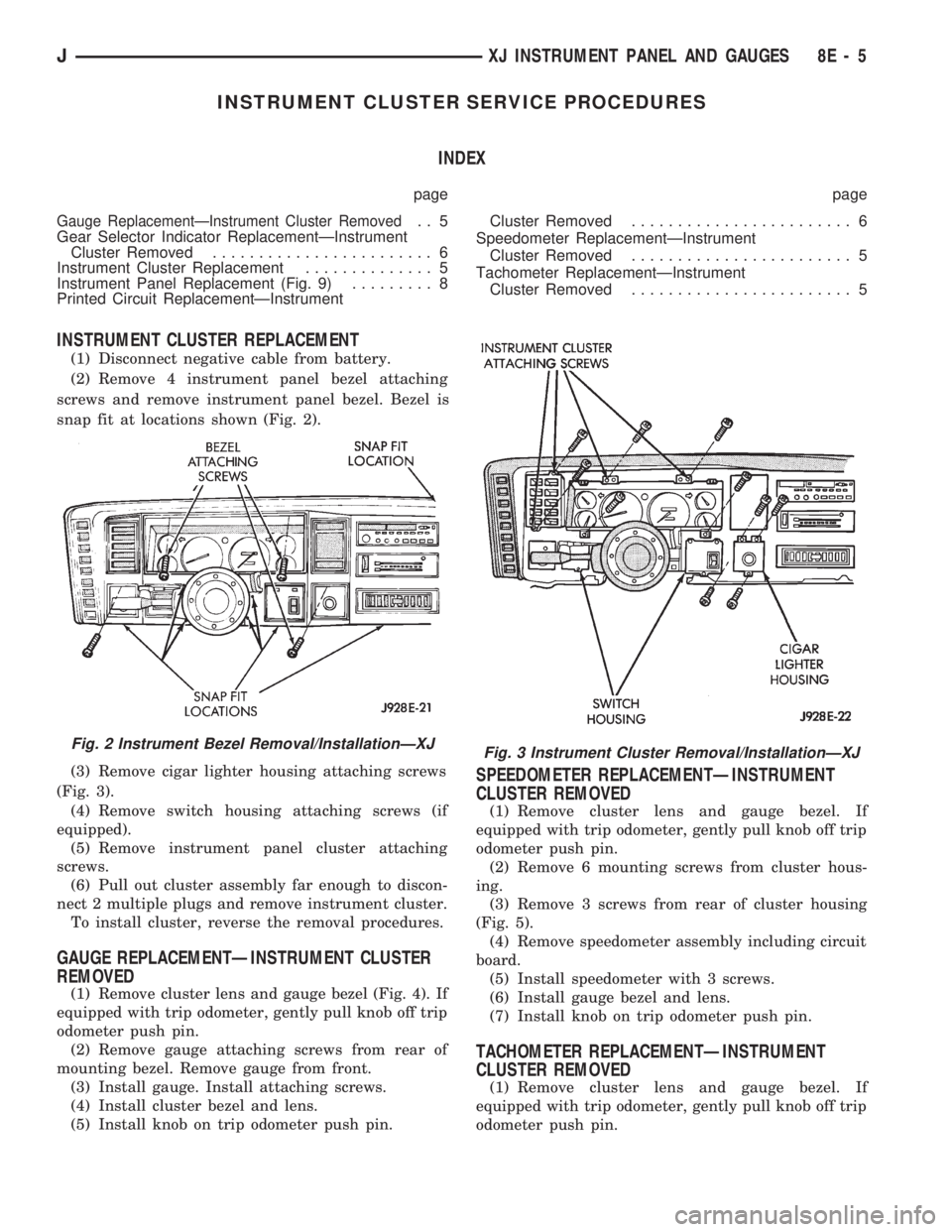
(2) Remove 4 instrument panel bezel attaching
screws and remove instrument panel bezel. Bezel is
snap fit at locations shown (Fig. 2).
(3) Remove cigar lighter housing attaching screws
(Fig. 3).
(4) Remove switch housing attaching screws (if
equipped).
(5) Remove instrument panel cluster attaching
screws.
(6) Pull out cluster assembly far enough to discon-
nect 2 multiple plugs and remove instrument cluster.
To install cluster, reverse the removal procedures.
GAUGE REPLACEMENTÐINSTRUMENT CLUSTER
REMOVED
(1) Remove cluster lens and gauge bezel (Fig. 4). If
equipped with trip odometer, gently pull knob off trip
odometer push pin.
(2) Remove gauge attaching screws from rear of
mounting bezel. Remove gauge from front.
(3) Install gauge. Install attaching screws.
(4) Install cluster bezel and lens.
(5) Install knob on trip odometer push pin.
SPEEDOMETER REPLACEMENTÐINSTRUMENT
CLUSTER REMOVED
(1) Remove cluster lens and gauge bezel. If
equipped with trip odometer, gently pull knob off trip
odometer push pin.
(2) Remove 6 mounting screws from cluster hous-
ing.
(3) Remove 3 screws from rear of cluster housing
(Fig. 5).
(4) Remove speedometer assembly including circuit
board.
(5) Install speedometer with 3 screws.
(6) Install gauge bezel and lens.
(7) Install knob on trip odometer push pin.
TACHOMETER REPLACEMENTÐINSTRUMENT
CLUSTER REMOVED
(1) Remove cluster lens and gauge bezel. If
equipped with trip odometer, gently pull knob off trip
odometer push pin.
Fig. 2 Instrument Bezel Removal/InstallationÐXJFig. 3 Instrument Cluster Removal/InstallationÐXJ
JXJ INSTRUMENT PANEL AND GAUGES 8E - 5
Page 361 of 1784

INSTRUMENT PANEL AND GAUGESÐYJE
CONTENTS
page page
GAUGE PACKAGE DIAGNOSIS............ 22
GAUGE PACKAGE GENERAL INFORMATION . 22
GAUGE PACKAGE SERVICE PROCEDURES . . 24
INSTRUMENT CLUSTER DIAGNOSIS....... 14INSTRUMENT CLUSTER GENERAL INFORMATION.14
INSTRUMENT CLUSTER SERVICE PROCEDURES.. 17
SPECIFICATIONS....................... 27
INSTRUMENT CLUSTER GENERAL INFORMATION
SPEEDOMETER/ODOMETER SYSTEM
The speedometer/odometer system consists of an
electric speedometer and pushbutton reset odometer
mounted in the cluster. The system also includes the
wire harness from the cluster to the vehicle speed
sensor at the transmission, and the adapter and pin-
ion in the transmission. A signal is sent from a
transmission mounted vehicle speed sensor to the
speedometer/odometer circuitry through the wiring
harness. Refer to Group 21 - Transmission for select-
ing the proper pinion, and selecting and indexing the
proper adapter.
TACHOMETER
The tachometer displays the engine speed (RPM).
With the engine running, the tachometer receives anengine speed signal from the Powertrain Control
Module pin 43 (values shown in Specifications chart).
INDICATOR LAMPS
The Brake, Upshift (2.5L with 5 speed transmis-
sion except California), and Malfunction Indicator
(Check Engine) lamps are located in the indicator
lamp panel above the steering column. The lamps
share a common battery feed connection through the
ignition switch and fuse #9.
The turn signals, high beam indicator, seat belt re-
minder, hazard lamp, master lighting and illumina-
tion bulbs are supplied battery voltage through
various switches and share a common ground.
INSTRUMENT CLUSTER DIAGNOSIS
INDEX
page page
Brake Indicator Lamp...................... 16
DiagnosingÐAll Lamps Out................. 16
Instrument Panel Illumination Lamps.......... 16
Malfunction Indicator Lamp (Check Engine)..... 16Seat Belt Reminder Lamp................... 16
Speedometer............................ 14
Tachometer............................. 14
Upshift Indicator Lamp..................... 16
SPEEDOMETER
(1) Raise vehicle.
(2) Disconnect the vehicle speed sensor connector.
(3) Connect a voltmeter between the black wire
pin of the connector and ground.
(4) Turn the ignition switch to the ON position.
(5) Check for approximately 5 volts. If OK, per-
form vehicle speed sensor test. Refer to the appropri-
ate Powertrain Diagnostic Procedures manual. If not
OK, continue with step 6.
(6) Turn ignition switch to OFF position.(7) Check continuity between vehicle speed sensor
connector and terminal 13 of instrument cluster con-
nector. If OK, replace speedometer. If not OK, repair
open circuit.
TACHOMETER
(1) Tachometer input is from the Powertrain Con-
trol Module (PCM) pin 43. Use the DRB scan tool to
perform actuator test. If OK, continue with step 2. If
not, replace PCM.
(2) Check for continuity between cluster connector
pin 12 and PCM pin 43. If OK, replace tachometer. If
not, repair open circuit.
8E - 14 YJ INSTRUMENT PANEL AND GAUGESJ
Page 363 of 1784

DIAGNOSINGÐALL LAMPS OUT
(1) Inspect fuse #9. Replace as required.
(2) Measure voltage at instrument cluster connec-
tor terminal 20. Meter should read zero ohms. If not,
repair open to ground.
UPSHIFT INDICATOR LAMP
Vehicles equipped with manual transmissions have
an optional upshift indicator lamp. The lamp is con-
trolled by the PCM. The lamp lights to indicate when
the driver should shift to the next highest gear for best
fuel economy. The PCM will turn the lamp off after 3 to
5 seconds if the upshift is not performed. The lamp will
remain off until the vehicle stops accelerating and is
brought back to the range of lamp operation or shifted
into another gear.
The indicator lamp is normally illuminated when
the ignition switch is turned ON and it is turned off
when the engine is started. The lamp will be lighted
during engine operation according to engine speed
and load.
(1) Turn ignition switch to ON.
(2) Ground pin 2 of cluster connector. Lamp should
light. If not, replace bulb. If OK, continue with step 3.
(3) Turn ignition switch to OFF. Check for conti-
nuity between cluster connector pin 2 and pin 54 of
the PCM. If not, repair open. If OK, refer to DRB
scan tool actuator test of upshift indicator.
BRAKE INDICATOR LAMP
The brake indicator is a dual function lamp. It will in-
dicate an unequal pressure condition in the split brake
hydraulic system and it also will indicate when the park-
ing brake is engaged. Separate switches are used for each
indicator lamp function. A switch mounted on the brake
pedal assembly will close a ground circuit whenever the
parking brakes are applied. A second switch is installed
in the brake hydraulic lines near the master cylinder. If
the switch is balanced by equal pressure on both ends of
the switch valve, the valve remains centered and the
lamp remains off. If the valve is shifted by unequal pres-
sure between the front or rear brake hydraulic systems,
the lamp circuit is connected to ground. To make sure
the brake lamp is functional before the vehicle is driven,
it is illuminated through a ground circuit when the igni-
tion switch is turned to the START position.
(1) Turn ignition switch to ON.
(2) Ground pin 1 of the cluster connector. Lamp
should light. If not, replace bulb. If OK, continue
with step 3.
(3) Turn ignition switch to OFF. Check for continuity to
park brake switch and brake warning switch.
MALFUNCTION INDICATOR LAMP (CHECK ENGINE)
The Malfunction Indicator Lamp (Check Engine) il-
luminates each time the ignition switch is turned
ON and stays on for 3 seconds as a bulb test.If the PCM receives an incorrect signal or no signal
from certain sensors or emission related systems the
lamp is turned on (pin 32 of PCM). This is a warning
that the PCM has recorded a system or sensor mal-
function. In some cases when a diagnostic fault is de-
clared the PCM will go into a limp-in mode in an
attempt to keep the system operating. It signals an
immediate need for service.
The lamp also can be used to display diagnostic
trouble codes (DTC). Cycle the ignition switch ON,
OFF, ON, OFF, ON within 5 seconds. This will allow
any DTC's stored in the PCM memory to be dis-
played in a series of flashes representing digits.
(1) Turn ignition switch to ON.
(2) Ground pin 4 of cluster connector. Lamp should
light. If not, replace bulb. If OK, continue with step 3.
(3) Turn ignition switch to OFF. Check for conti-
nuity between cluster connector pin 4 and PCM cav-
ity 32. If OK, replace PCM. If not, repair open.
SEAT BELT REMINDER LAMP
Apply 12 volts to terminal 16 of cluster connector.
Lamp should light. If not, replace bulb. If OK, check
wiring for an open to buzzer module. Refer to Group
8U - Chime/Buzzer Warning Systems.
INSTRUMENT PANEL ILLUMINATION LAMPS
The instrument panel illumination lamps share
two common connections. There is a splice after fuse
#10 that connects the lamps to battery feed. There is
also a splice that connects all lamps to ground. Be-
cause they share these common connection points in
a parallel circuit, the illumination lamps will all
come on at the same time. It also means one or more
lamps can be out without affecting the operation of
the other lamps.
On the battery side of the circuit, the headlamp
switch illumination rheostat/switch and panel lamps
fuse receive battery feed in series from the park/tail
fuse. In the park lamp position, the headlamp switch
completes the circuit from the park/tail fuse to the il-
lumination rheostat/switch and panel lamps fuse.
The illumination rheostat contains a variable resis-
tor that allows the driver to vary illumination inten-
sity from off to full brightness.
DIAGNOSIS
(1) Turn parking lamps ON.
(2) Check fuse #10. Replace as required.
(3) Measure voltage at battery side of fuse #10
with rheostat turned counterclockwise to clockwise
(LO to HI). Meter should read zero volts to battery
voltage. If not, replace headlamp switch.
(4) Measure resistance at ground side of fuse #10
with parking lamps OFF. Meter should read almost
zero ohms (except bulb filament). If not, repair open
to ground. If zero ohms, 12 volt supply wire from fuse
is shorted to ground, repair short.
8E - 16 YJ INSTRUMENT PANEL AND GAUGESJ
Page 364 of 1784

INSTRUMENT CLUSTER SERVICE PROCEDURES
INDEX
page page
Headlamp Switch/Illumination Rheostat........ 21
Indicator Bezel Replacement................ 17
Instrument Cluster Bulb Replacement......... 19
Instrument Cluster Replacement............. 17Printed Circuit Replacement................ 19
Rear Defogger/Fog Lamp/Rear Wiper Switches . . 21
Speedometer Replacement................. 17
Tachometer Replacement.................. 17
INSTRUMENT CLUSTER REPLACEMENT
(1) Remove 6 shroud screws (Fig. 1).
(2) Slide shroud toward steering wheel.
(3) Remove 3 screws holding right side switch
panel (Fig. 2).
(4) Remove 3 screws holding left side switch bezel.(5) Remove 2 screws holding cluster in place.
(6) Lift up top of cluster. Roll cluster out between
steering column and instrument panel far enough to
reach connector located behind tachometer.
(7) Disconnect cluster connector and remove clus-
ter (Fig. 3).
(8) To install cluster, reverse the removal proce-
dures.
TACHOMETER REPLACEMENT
(1) Disconnect negative cable from battery.
(2) Remove instrumentation shroud (Fig. 1). Refer
to Instrument Cluster Replacement.
(3) Remove cluster as described in Instrument
Cluster replacement.
(4) Remove 3 screws and tachometer lens (Fig. 4).
(5) Gently pry up clip to release lens from bezel
(Fig. 5).
(6) Remove 3 screws from rear of housing (Fig. 6).
Remove tachometer.
(7) Install tachometer with 3 screws.
(8) Snap lens into place.
(9) Install lens with 3 screws.
(10) To install the cluster, reverse the removal pro-
cedures.
SPEEDOMETER REPLACEMENT
(1) Disconnect negative cable from battery.
(2) Remove instrument shroud (Fig. 1). Refer to In-
strument Cluster Replacement.
(3) Remove cluster as described in Instrument
Cluster Replacement.
(4) Remove 3 screws and speedometer lens (Fig. 7).
(5) Gently pry up clip to release lens from bezel
(Fig. 5).
(6) Remove 3 screws from rear of housing (Fig. 8).
Remove speedometer.
(7) Install speedometer with 3 screws.
(8) Snap lens into place.
(9) Install lens with 3 screws.
(10) To install the cluster, reverse the removal pro-
cedures.
INDICATOR BEZEL REPLACEMENT
(1) Disconnect negative cable from battery.
(2) Remove instrumentation shroud (Fig. 1).
(3) Remove 3 screws and tachometer lens (Fig. 4).
Fig. 2 Cluster Removal
Fig. 1 Instrument Shroud Removal/Installation
JYJ INSTRUMENT PANEL AND GAUGES 8E - 17
Page 371 of 1784

GAUGE PACKAGE SERVICE PROCEDURES
PRINTED CIRCUIT REMOVAL
DISASSEMBLY
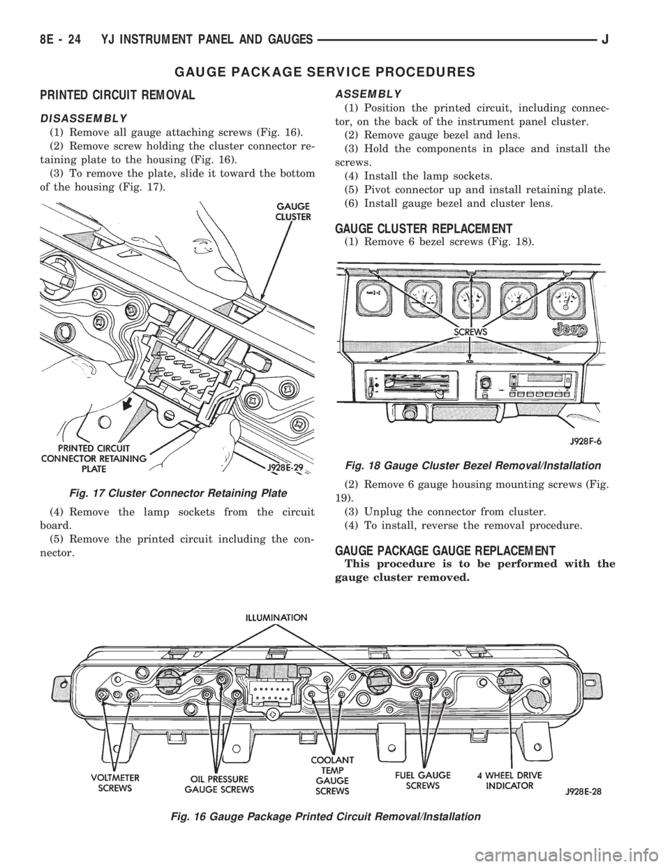
(1) Remove all gauge attaching screws (Fig. 16).
(2) Remove screw holding the cluster connector re-
taining plate to the housing (Fig. 16).
(3) To remove the plate, slide it toward the bottom
of the housing (Fig. 17).
(4) Remove the lamp sockets from the circuit
board.
(5) Remove the printed circuit including the con-
nector.
ASSEMBLY
(1) Position the printed circuit, including connec-
tor, on the back of the instrument panel cluster.
(2) Remove gauge bezel and lens.
(3) Hold the components in place and install the
screws.
(4) Install the lamp sockets.
(5) Pivot connector up and install retaining plate.
(6) Install gauge bezel and cluster lens.
GAUGE CLUSTER REPLACEMENT
(1) Remove 6 bezel screws (Fig. 18).
(2) Remove 6 gauge housing mounting screws (Fig.
19).
(3) Unplug the connector from cluster.
(4) To install, reverse the removal procedure.
GAUGE PACKAGE GAUGE REPLACEMENT
This procedure is to be performed with the
gauge cluster removed.
Fig. 16 Gauge Package Printed Circuit Removal/Installation
Fig. 17 Cluster Connector Retaining Plate
Fig. 18 Gauge Cluster Bezel Removal/Installation
8E - 24 YJ INSTRUMENT PANEL AND GAUGESJ