1994 JEEP CHEROKEE service
[x] Cancel search: servicePage 303 of 1784
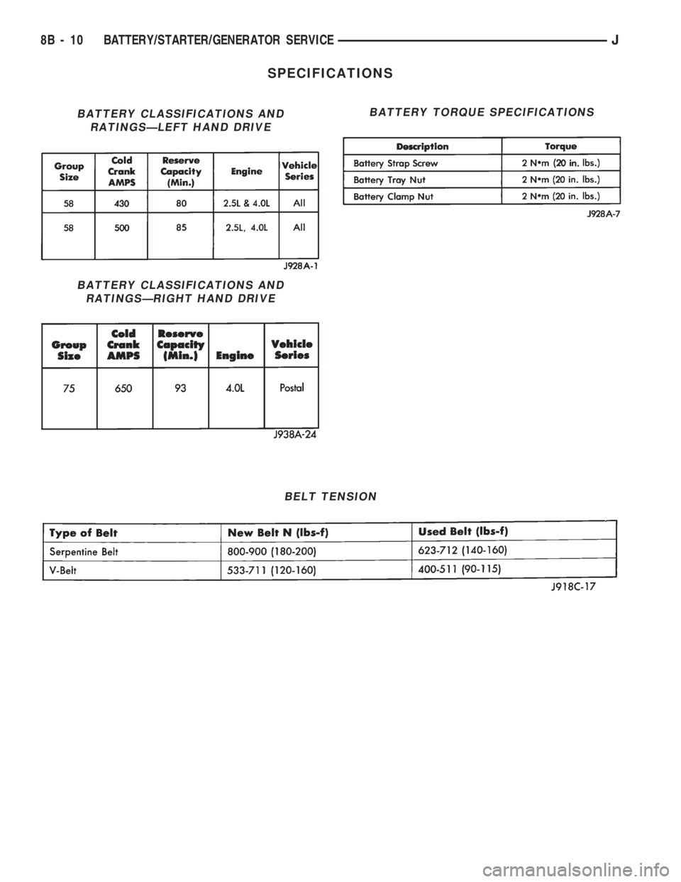
SPECIFICATIONS
BATTERY CLASSIFICATIONS AND
RATINGSÐLEFT HAND DRIVE
BATTERY CLASSIFICATIONS AND
RATINGSÐRIGHT HAND DRIVE
BATTERY TORQUE SPECIFICATIONS
BELT TENSION
8B - 10 BATTERY/STARTER/GENERATOR SERVICEJ
Page 304 of 1784
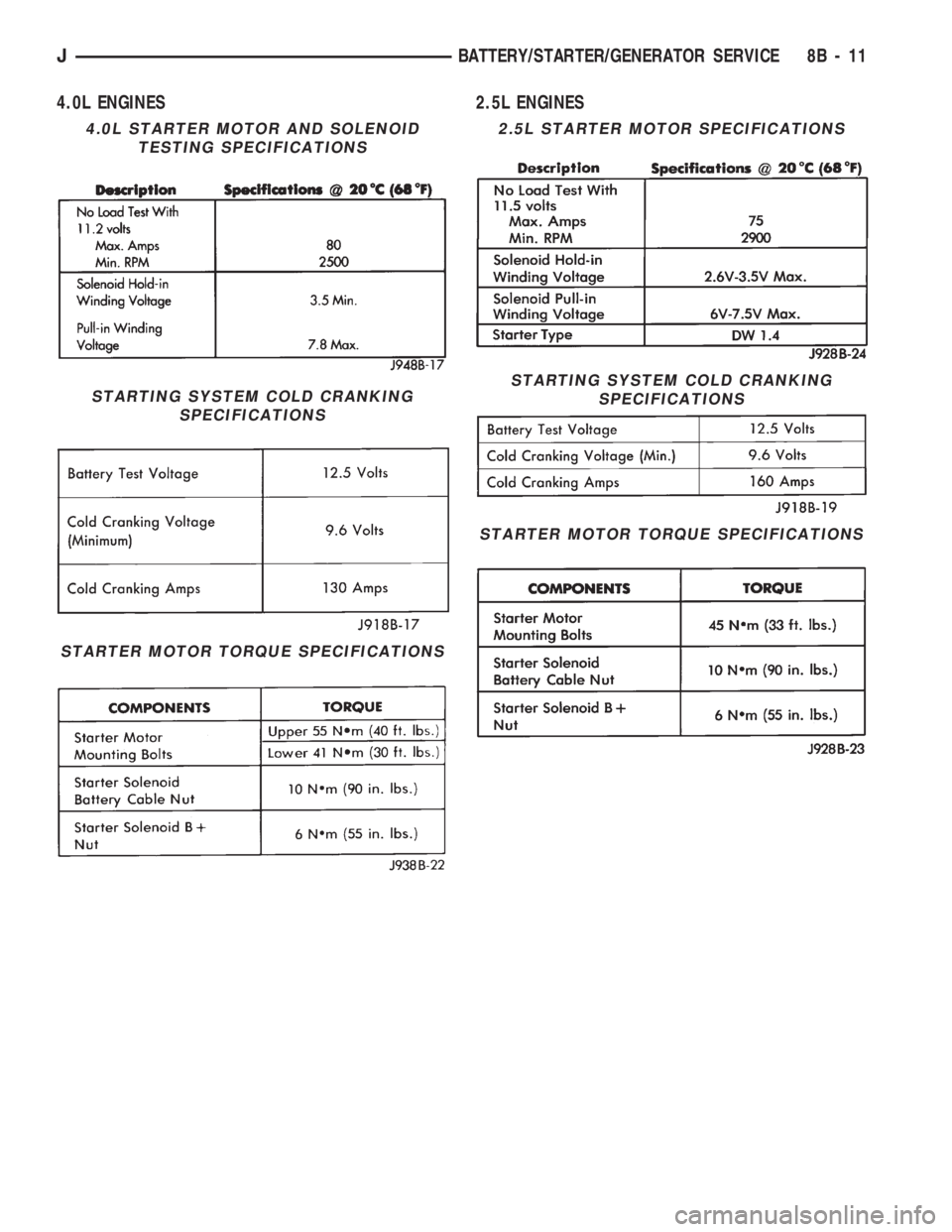
4.0L ENGINES 2.5L ENGINES
4.0L STARTER MOTOR AND SOLENOID
TESTING SPECIFICATIONS
STARTING SYSTEM COLD CRANKING
SPECIFICATIONS
STARTER MOTOR TORQUE SPECIFICATIONS
2.5L STARTER MOTOR SPECIFICATIONS
STARTING SYSTEM COLD CRANKING
SPECIFICATIONS
STARTER MOTOR TORQUE SPECIFICATIONS
JBATTERY/STARTER/GENERATOR SERVICE 8B - 11
Page 305 of 1784
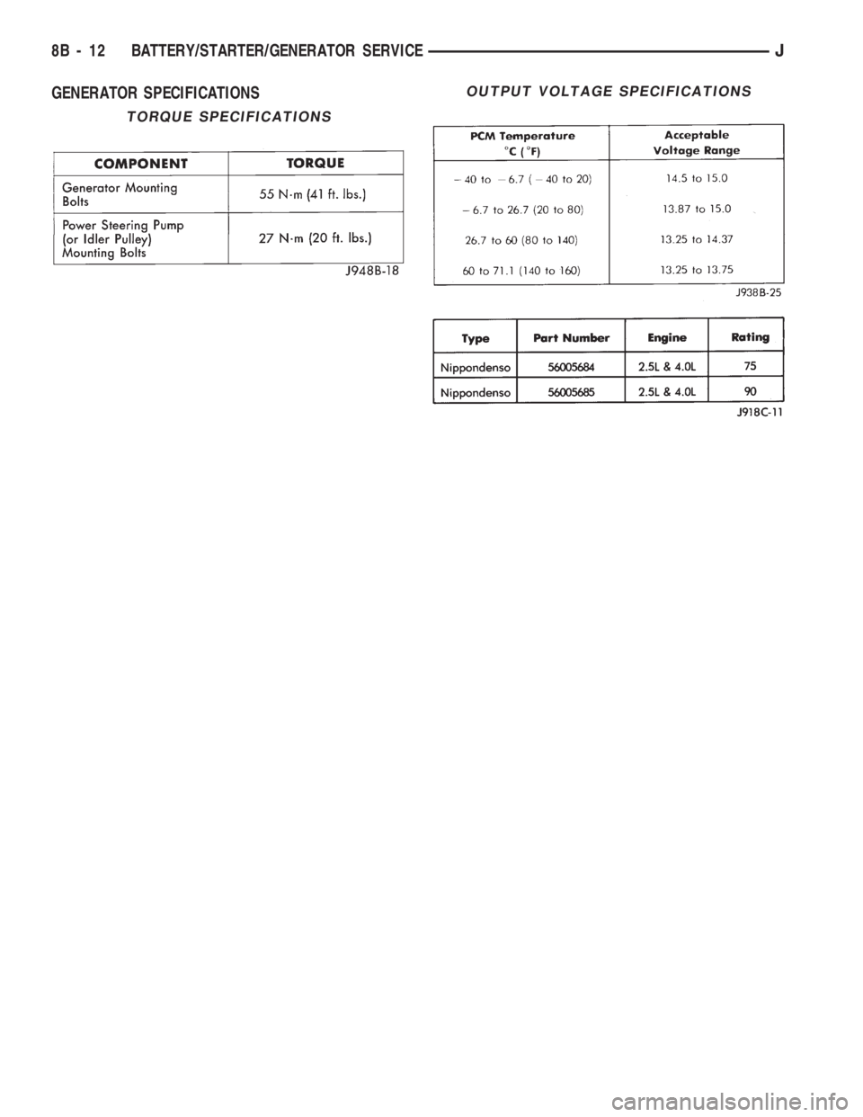
GENERATOR SPECIFICATIONS
TORQUE SPECIFICATIONS
OUTPUT VOLTAGE SPECIFICATIONS
8B - 12 BATTERY/STARTER/GENERATOR SERVICEJ
Page 314 of 1784

IGNITION SYSTEMS
CONTENTS
page page
COMPONENT IDENTIFICATION/SYSTEM
OPERATION.......................... 1
COMPONENT REMOVAL/INSTALLATION..... 20DIAGNOSTICS/SERVICE PROCEDURES....... 8
IGNITION SWITCH...................... 30
SPECIFICATIONS....................... 33
COMPONENT IDENTIFICATION/SYSTEM OPERATION
INDEX
page page
Automatic Shut Down (ASD) Relay............ 1
Camshaft Position Sensor................... 1
Crankshaft Position Sensor.................. 2
Distributors.............................. 3
Engine Coolant Temperature Sensor........... 4
General Information........................ 1Ignition Coil.............................. 4
Intake Manifold Air Temperature Sensor........ 5
Manifold Absolute Pressure (MAP) Sensor...... 5
Powertrain Control Module (PCM)............. 6
Throttle Position Sensor.................... 6
GENERAL INFORMATION
Throughout this group, references are made to par-
ticular vehicle models by alphabetical designation
(XJ or YJ) or by the particular vehicle nameplate. A
chart showing a breakdown of alphabetical designa-
tions is included in the Introduction group at the be-
ginning of this manual.
This section of the group, Component Identifica-
tion/System Operation, will discuss ignition system
operation and will identify ignition system compo-
nents.
For diagnostic procedures and adjustments, refer to
the Diagnostics/Service Procedures section of this
group.
For removal and installation of ignition system
components, refer to the Component Removal/Instal-
lation section of this group.
For other useful information, refer to On-Board Di-
agnostics in the General Diagnosis sections of Group
14, Fuel System in this manual.
For operation of the DRB Scan Tool, refer to the
appropriate Powertrain Diagnostic Procedures ser-
vice manual.
An Ignition specifications section is included at the
end of this group. A general Maintenance Schedule
(mileage intervals) for ignition related items can be
found in Group 0, Lubrication and Maintenance. This
schedule can also be found in the Owners Manual.
IGNITION SYSTEMS
A multi-port, fuel injected engine is used on all
models. The ignition system is controlled by the Pow-
ertrain Control Module (PCM) on all engines. The
PCM was formerly referred to as the SBEC or engine
controller.
The ignition system consists of:
²Spark Plugs
²Ignition Coil
²Secondary Ignition Cables
²Ignition distributor (contains rotor and camshaft
position sensor)
²Powertrain Control Module (PCM)
²Crankshaft Position Sensor
AUTOMATIC SHUT DOWN (ASD) RELAY
The automatic shut down (ASD) relay is located in
the Power Distribution Center (PDC) near the bat-
tery (Fig. 1 or 2). As one of its functions, it will sup-
ply battery voltage to the ignition coil. The ground
circuit for the ASD relay is controlled by the Power-
train Control Module (PCM). The PCM regulates
ASD relay operation by switching the ground circuit
on-and-off.
CAMSHAFT POSITION SENSOR
The camshaft position sensor is located in the igni-
tion distributor (Figs. 3 or 4) on all engines.
The camshaft position sensor contains a hall effect
device called a sync signal generator to generate a
fuel sync signal. This sync signal generator detects a
JIGNITION SYSTEMS 8D - 1
Page 317 of 1784
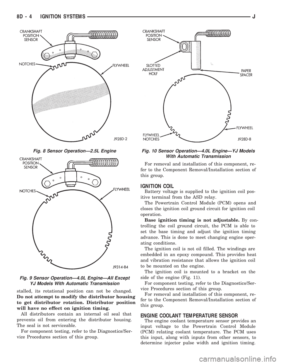
stalled, its rotational position can not be changed.
Do not attempt to modify the distributor housing
to get distributor rotation. Distributor position
will have no effect on ignition timing.
All distributors contain an internal oil seal that
prevents oil from entering the distributor housing.
The seal is not serviceable.
For component testing, refer to the Diagnostics/Ser-
vice Procedures section of this group.For removal and installation of this component, re-
fer to the Component Removal/Installation section of
this group.
IGNITION COIL
Battery voltage is supplied to the ignition coil pos-
itive terminal from the ASD relay.
The Powertrain Control Module (PCM) opens and
closes the ignition coil ground circuit for ignition coil
operation.
Base ignition timing is not adjustable.By con-
trolling the coil ground circuit, the PCM is able to
set the base timing and adjust the ignition timing
advance. This is done to meet changing engine oper-
ating conditions.
The ignition coil is not oil filled. The windings are
embedded in an epoxy compound. This provides heat
and vibration resistance that allows the ignition coil
to be mounted on the engine.
The ignition coil is mounted to a bracket on the
side of the engine (Fig. 11).
For component testing, refer to the Diagnostics/Ser-
vice Procedures section of this group.
For removal and installation of this component, re-
fer to the Component Removal/Installation section of
this group.
ENGINE COOLANT TEMPERATURE SENSOR
The engine coolant temperature sensor provides an
input voltage to the Powertrain Control Module
(PCM) relating coolant temperature. The PCM uses
this input, along with inputs from other sensors, to
determine injector pulse width and ignition timing.
Fig. 8 Sensor OperationÐ2.5L Engine
Fig. 9 Sensor OperationÐ4.0L EngineÐAll Except
YJ Models With Automatic Transmission
Fig. 10 Sensor OperationÐ4.0L EngineÐYJ Models
With Automatic Transmission
8D - 4 IGNITION SYSTEMSJ
Page 319 of 1784
sensor voltage to change. This change results in a
different input voltage to the PCM. The input volt-
age level supplies the PCM with information. This
relates to ambient barometric pressure during engine
start-up (cranking) and to engine load while the en-
gine is running. The PCM uses this input, along with
inputs from other sensors, to adjust air-fuel mixture.
For more information, refer to Group 14, Fuel Sys-
tem.
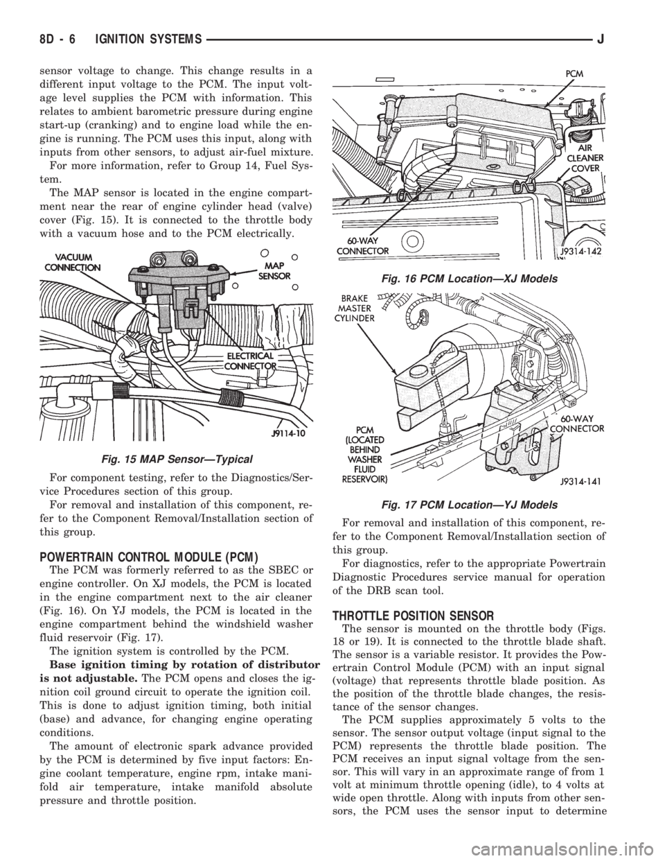
The MAP sensor is located in the engine compart-
ment near the rear of engine cylinder head (valve)
cover (Fig. 15). It is connected to the throttle body
with a vacuum hose and to the PCM electrically.
For component testing, refer to the Diagnostics/Ser-
vice Procedures section of this group.
For removal and installation of this component, re-
fer to the Component Removal/Installation section of
this group.
POWERTRAIN CONTROL MODULE (PCM)
The PCM was formerly referred to as the SBEC or
engine controller. On XJ models, the PCM is located
in the engine compartment next to the air cleaner
(Fig. 16). On YJ models, the PCM is located in the
engine compartment behind the windshield washer
fluid reservoir (Fig. 17).
The ignition system is controlled by the PCM.
Base ignition timing by rotation of distributor
is not adjustable.The PCM opens and closes the ig-
nition coil ground circuit to operate the ignition coil.
This is done to adjust ignition timing, both initial
(base) and advance, for changing engine operating
conditions.
The amount of electronic spark advance provided
by the PCM is determined by five input factors: En-
gine coolant temperature, engine rpm, intake mani-
fold air temperature, intake manifold absolute
pressure and throttle position.For removal and installation of this component, re-
fer to the Component Removal/Installation section of
this group.
For diagnostics, refer to the appropriate Powertrain
Diagnostic Procedures service manual for operation
of the DRB scan tool.
THROTTLE POSITION SENSOR
The sensor is mounted on the throttle body (Figs.
18 or 19). It is connected to the throttle blade shaft.
The sensor is a variable resistor. It provides the Pow-
ertrain Control Module (PCM) with an input signal
(voltage) that represents throttle blade position. As
the position of the throttle blade changes, the resis-
tance of the sensor changes.
The PCM supplies approximately 5 volts to the
sensor. The sensor output voltage (input signal to the
PCM) represents the throttle blade position. The
PCM receives an input signal voltage from the sen-
sor. This will vary in an approximate range of from 1
volt at minimum throttle opening (idle), to 4 volts at
wide open throttle. Along with inputs from other sen-
sors, the PCM uses the sensor input to determine
Fig. 15 MAP SensorÐTypical
Fig. 16 PCM LocationÐXJ Models
Fig. 17 PCM LocationÐYJ Models
8D - 6 IGNITION SYSTEMSJ
Page 321 of 1784

DIAGNOSTICS/SERVICE PROCEDURES
INDEX
page page
Automatic Shut Down (ASD) Relay............ 8
Camshaft Position Sensor Test............... 8
Crankshaft Position Sensor Test.............. 9
Distributor Cap........................... 9
Distributor Rotor......................... 10
DRB Scan Tool.......................... 10
Engine Coolant Temperature Sensor Test...... 12
General Information........................ 8
Ignition Coil............................. 11
Ignition Secondary Circuit Diagnosis.......... 12Ignition Timing........................... 14
Intake Manifold Air Temperature Sensor Test . . . 14
Manifold Absolute Pressure (MAP) Sensor Test . 14
On-Board Diagnostics (OBD)................ 19
Oxygen Sensor Tests..................... 19
Powertrain Control Module (PCM)............ 15
Spark Plug Secondary Cables............... 17
Spark Plugs............................ 16
Throttle Position Sensor Test............... 18
GENERAL INFORMATION
This section of the group, Diagnostics/Service Pro-
cedures, will discuss basic ignition system diagnos-
tics and service adjustments.
For system operation and component identification,
refer to the Component Identification/System Opera-
tion section of this group.
For removal or installation of ignition system com-
ponents, refer to the Component Removal/Installa-
tion section of this group.
For other useful information, refer to On-Board Di-
agnostics in the General Diagnosis sections of Group
14, Fuel System in this manual.
For operation of the DRB Scan Tool, refer to the
appropriate Powertrain Diagnostic Procedures ser-
vice manual.
AUTOMATIC SHUT DOWN (ASD) RELAY
Refer to RelaysÐOperation/Testing in the Group
14, Fuel System section of this service manual.
CAMSHAFT POSITION SENSOR TEST
The camshaft position sensor is located in the dis-
tributor on all engines.
To perform a complete test of this sensor and its
circuitry, refer to the DRB scan tool. Also refer to the
appropriate Powertrain Diagnostics Procedures man-
ual. To test the sensor only, refer to the following:
2.5L OR 4.0L ENGINE
For this test, an analog voltmeter is needed.Do
not remove the distributor connector from the dis-
tributor. Using small paper clips, insert them into
the backside of the distributor wire harness connec-
tor to make contact with the terminals. Be sure that
the connector is not damaged when inserting the pa-
per clips. Attach voltmeter leads to these paper clips.
(1) Connect the positive (+) voltmeter lead into
the sensor output wire. This is at done the distribu-
tor wire harness connector. For wire identification,
refer to Group 8W, Wiring Diagrams.(2) Connect the negative (-) voltmeter lead into the
ground wire. For wire identification, refer to Group
8W, Wiring Diagrams.
(3) Set the voltmeter to the 15 Volt DC scale.
(4) Remove distributor cap. Rotate (crank) engine
with starter until pulse ring (Fig. 1) enters the mag-
netic pickup on camshaft position sensor. Distributor
rotor should be pointed in 9 o'clock position. The
movable pulse ring should now be within the sensor
pickup.
(5) Turn ignition key to ON position. Voltmeter
should read approximately 5.0 volts.
(6) If voltage is not present, check the voltmeter
leads for a good connection.
(7) If voltage is still not present, check for voltage
at the supply wire. For wire identification, refer to
Group 8W, Wiring Diagrams.
Fig. 1 Pulse Ring/Rotor PositionÐTypical
8D - 8 IGNITION SYSTEMSJ
Page 323 of 1784
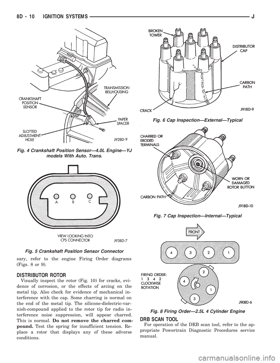
sary, refer to the engine Firing Order diagrams
(Figs. 8 or 9).
DISTRIBUTOR ROTOR
Visually inspect the rotor (Fig. 10) for cracks, evi-
dence of corrosion, or the effects of arcing on the
metal tip. Also check for evidence of mechanical in-
terference with the cap. Some charring is normal on
the end of the metal tip. The silicone-dielectric-var-
nish-compound applied to the rotor tip for radio in-
terference noise suppression, will appear charred.
This is normal.Do not remove the charred com-
pound.Test the spring for insufficient tension. Re-
place a rotor that displays any of these adverse
conditions.
DRB SCAN TOOL
For operation of the DRB scan tool, refer to the ap-
propriate Powertrain Diagnostic Procedures service
manual.
Fig. 4 Crankshaft Position SensorÐ4.0L EngineÐYJ
models With Auto. Trans.
Fig. 5 Crankshaft Position Sensor Connector
Fig. 6 Cap InspectionÐExternalÐTypical
Fig. 7 Cap InspectionÐInternalÐTypical
Fig. 8 Firing OrderÐ2.5L 4 Cylinder Engine
8D - 10 IGNITION SYSTEMSJ