1994 JEEP CHEROKEE tow
[x] Cancel search: towPage 1540 of 1784
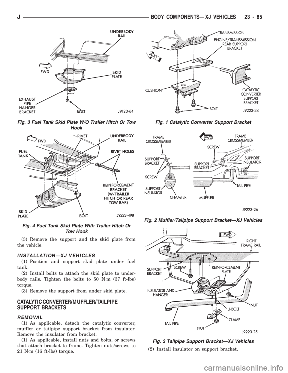
(3) Remove the support and the skid plate from
the vehicle.
INSTALLATIONÐXJ VEHICLES
(1) Position and support skid plate under fuel
tank.
(2) Install bolts to attach the skid plate to under-
body rails. Tighten the bolts to 50 Nzm (37 ft-lbs)
torque.
(3) Remove the support from under skid plate.
CATALYTIC CONVERTER/MUFFLER/TAILPIPE
SUPPORT BRACKETS
REMOVAL
(1) As applicable, detach the catalytic converter,
muffler or tailpipe support bracket from insulator.
Remove the insulator from bracket.
(1) As applicable, install nuts and bolts, or screws
that attach bracket to frame. Tighten nuts/screws to
21 Nzm (16 ft-lbs) torque.(2) Install insulator on support bracket.
Fig. 1 Catalytic Converter Support Bracket
Fig. 2 Muffler/Tailpipe Support BracketÐXJ Vehicles
Fig. 3 Tailpipe Support BracketÐXJ Vehicles
Fig. 3 Fuel Tank Skid Plate W/O Trailer Hitch Or Tow
Hook
Fig. 4 Fuel Tank Skid Plate With Trailer Hitch Or
Tow Hook
JBODY COMPONENTSÐXJ VEHICLES 23 - 85
Page 1542 of 1784
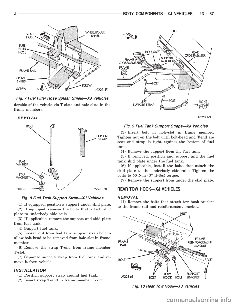
derside of the vehicle via T-slots and hole-slots in the
frame members.
REMOVAL
(1) If equipped, position a support under skid plate.
(2) If equipped, remove the bolts that attach skid
plate to underbody side rails.
(3) If applicable, remove the support and skid plate
from fuel tank.
(4) Support fuel tank.
(5) Loosen nut from fuel tank support strap bolt to
allow bolt head to be removed from hole-slot in frame
member.
(6) Remove the strap T-end from frame member
T-slot.
(7) Separate support strap from fuel tank and re-
move it from vehicle.
INSTALLATION
(1) Position support strap around fuel tank.
(2) Insert strap T-end in frame member T-slot.(3) Insert bolt in hole-slot in frame member.
Tighten nut on the bolt until bolt-head and T-end are
seat and strap is tight against the bottom of fuel
tank.
(4) Remove the support from the fuel tank.
(5) If removed, position and support and the fuel
tank skid plate under the fuel tank.
(6) If applicable, install the bolts that attach the
skid plate to the underbody side rails. Tighten the
bolts to 50 Nzm (37 ft-lbs) torque.
(7) Remove the support from under the skid plate.
REAR TOW HOOKÐXJ VEHICLES
REMOVAL
(1) Remove the bolts that attach tow hook bracket
to the frame rail and reinforcement bracket.
Fig. 7 Fuel Filler Hose Splash ShieldÐXJ Vehicles
Fig. 8 Fuel Tank Support StrapÐXJ Vehicles
Fig. 9 Fuel Tank Support StrapsÐXJ Vehicles
Fig. 10 Rear Tow HookÐXJ Vehicles
JBODY COMPONENTSÐXJ VEHICLES 23 - 87
Page 1543 of 1784
The reinforcement bracket is held on the
frame rail with two blind rivets.
(2) Remove the bracket and tow hook from frame
rail.
INSTALLATION
(1) Position bracket and tow hook on the frame
rail.
(2) Install bolts that attach tow hook bracket to
frame rail and reinforcement bracket. Tighten bolts
to 75 Nzm (55 ft-lbs) torque.
TRAILER HITCHES
CLASS III HITCHÐXJ VEHICLES
A class III weight-distributing/equalizer type hitch
can be used to tow a trailer:
²having a maximum gross weight of 5,000 lbs/2250
kg, and
²having a maximum tongue weight of 750 lbs/332
kg).
The following vehicle basic equipment is required
for class III trailer towing:
²P205/75R15 or larger tires;
²full size spare tire;
²trailer sway control;
²trailer tow wire harness and connector;
²heavy duty turn signal flasher element;
²heavy duty axle (with synthetic lubricant);²heavy duty cooling system;
²heavy duty generator/battery;
²auxiliary automatic transmission fluid cooler; and
²I-6, 4.0L engine.
Wide-angle type door mirrors are recommended but
not required.
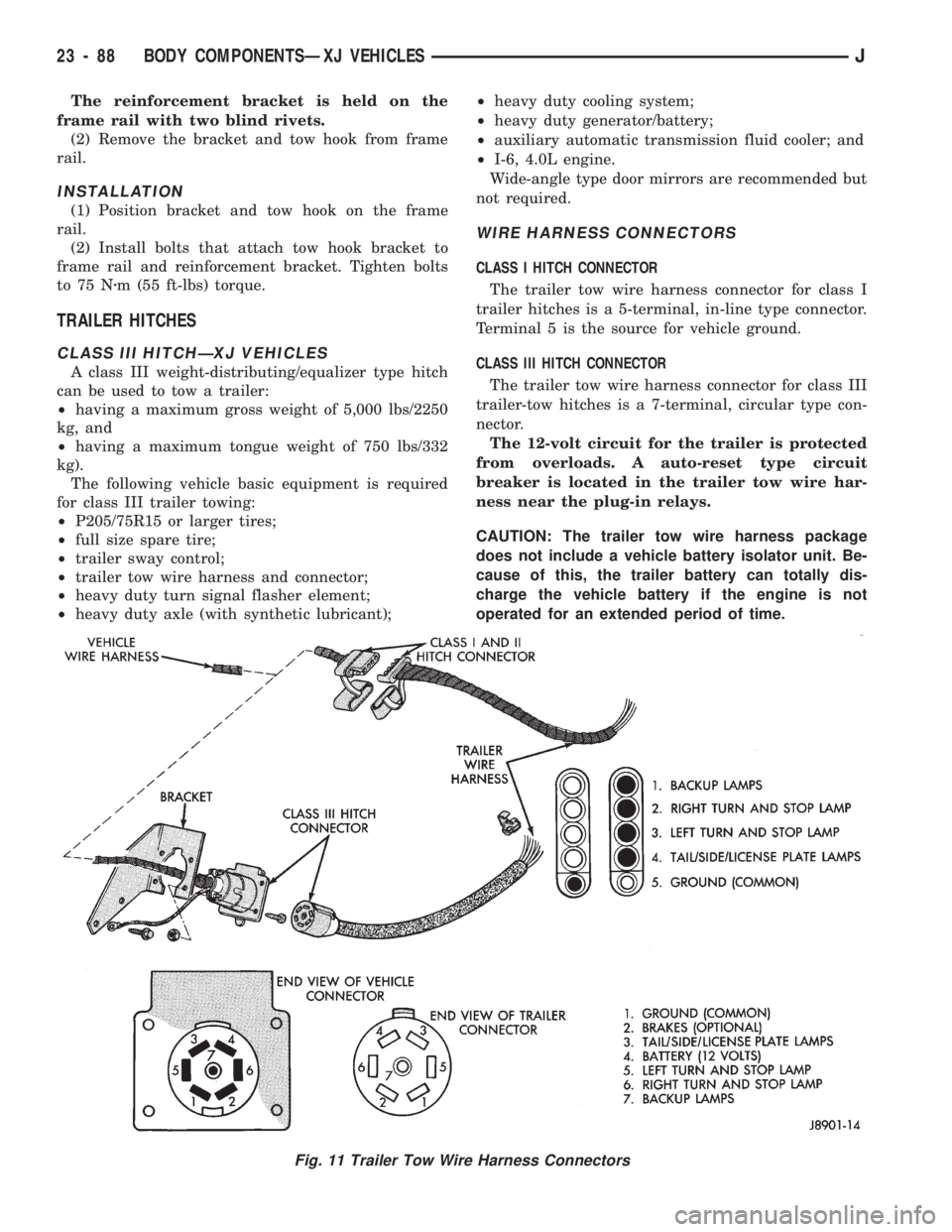
WIRE HARNESS CONNECTORS
CLASS I HITCH CONNECTOR
The trailer tow wire harness connector for class I
trailer hitches is a 5-terminal, in-line type connector.
Terminal 5 is the source for vehicle ground.
CLASS III HITCH CONNECTOR
The trailer tow wire harness connector for class III
trailer-tow hitches is a 7-terminal, circular type con-
nector.
The 12-volt circuit for the trailer is protected
from overloads. A auto-reset type circuit
breaker is located in the trailer tow wire har-
ness near the plug-in relays.
CAUTION: The trailer tow wire harness package
does not include a vehicle battery isolator unit. Be-
cause of this, the trailer battery can totally dis-
charge the vehicle battery if the engine is not
operated for an extended period of time.
Fig. 11 Trailer Tow Wire Harness Connectors
23 - 88 BODY COMPONENTSÐXJ VEHICLESJ
Page 1544 of 1784
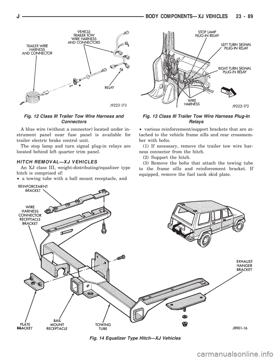
A blue wire (without a connector) located under in-
strument panel near fuse panel is available for
trailer electric brake control unit.
The stop lamp and turn signal plug-in relays are
located behind left quarter trim panel.
HITCH REMOVALÐXJ VEHICLES
An XJ class III, weight-distributing/equalizer type
hitch is comprised of:
²a towing tube with a ball mount receptacle, and²various reinforcement/support brackets that are at-
tached to the vehicle frame sills and rear crossmem-
ber with bolts.
(1) If necessary, remove the trailer tow wire har-
ness connector from the hitch.
(2) Support the hitch.
(3) Remove the bolts that attach the towing tube
to the frame sills and reinforcement bracket. If
equipped, remove the fuel tank skid plate.
Fig. 14 Equalizer Type HitchÐXJ Vehicles
Fig. 12 Class III Trailer Tow Wire Harness and
ConnectorsFig. 13 Class III Trailer Tow Wire Harness Plug-In
Relays
JBODY COMPONENTSÐXJ VEHICLES 23 - 89
Page 1545 of 1784
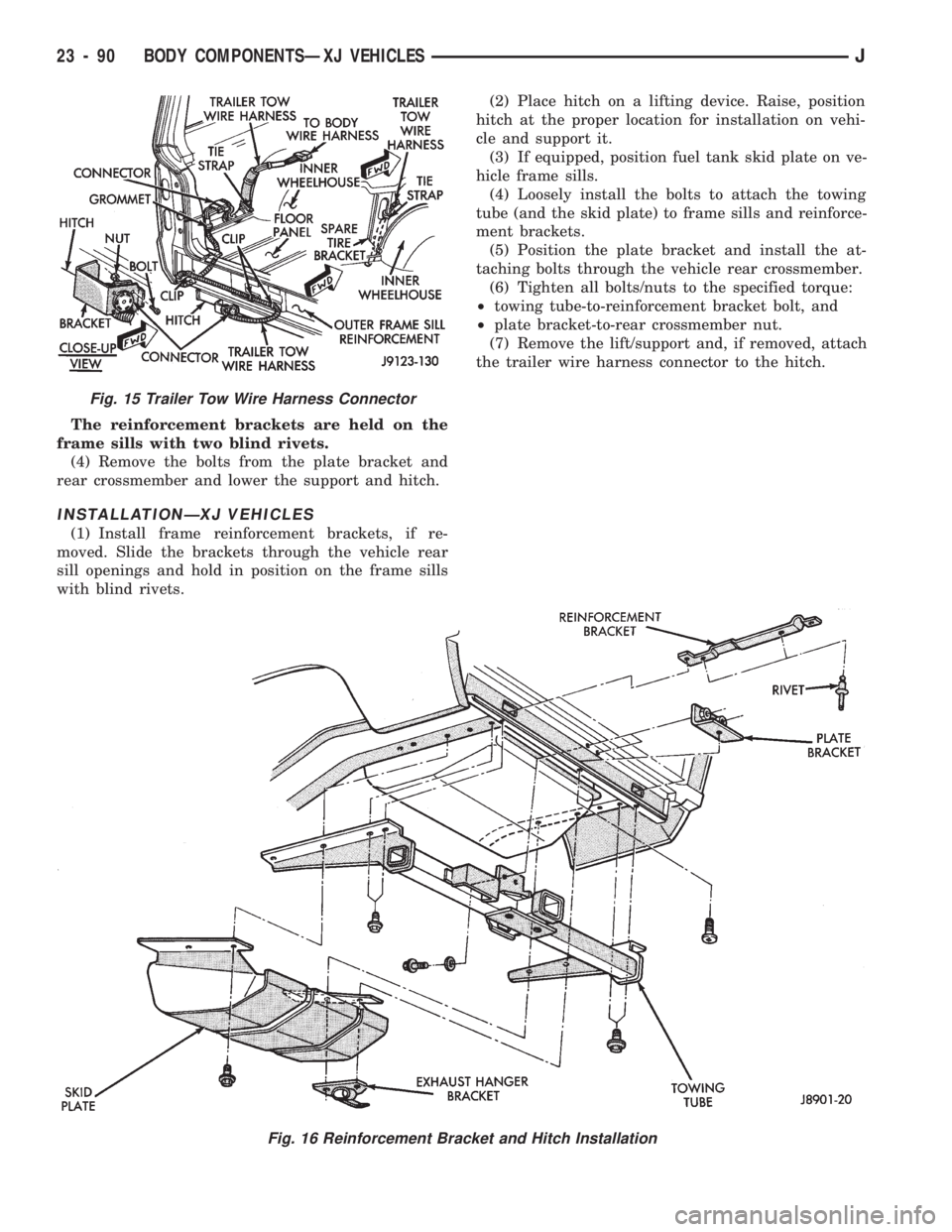
The reinforcement brackets are held on the
frame sills with two blind rivets.
(4) Remove the bolts from the plate bracket and
rear crossmember and lower the support and hitch.
INSTALLATIONÐXJ VEHICLES
(1) Install frame reinforcement brackets, if re-
moved. Slide the brackets through the vehicle rear
sill openings and hold in position on the frame sills
with blind rivets.(2) Place hitch on a lifting device. Raise, position
hitch at the proper location for installation on vehi-
cle and support it.
(3) If equipped, position fuel tank skid plate on ve-
hicle frame sills.
(4) Loosely install the bolts to attach the towing
tube (and the skid plate) to frame sills and reinforce-
ment brackets.
(5) Position the plate bracket and install the at-
taching bolts through the vehicle rear crossmember.
(6) Tighten all bolts/nuts to the specified torque:
²towing tube-to-reinforcement bracket bolt, and
²plate bracket-to-rear crossmember nut.
(7) Remove the lift/support and, if removed, attach
the trailer wire harness connector to the hitch.
Fig. 15 Trailer Tow Wire Harness Connector
Fig. 16 Reinforcement Bracket and Hitch Installation
23 - 90 BODY COMPONENTSÐXJ VEHICLESJ
Page 1609 of 1784
The following equipment and material are neces-
sary for body stripe/decal removal and installation:
²a commercial tape stripe/decal removal solution;
²a commercial adhesive removal solution;
²liquid dish detergent (for the wetting solution);
²a mixture of wetting solution;
²a commercial wax and silicone removal solution;
²isopropyl (rubbing) alcohol;
²a small squeegee (plastic or hard rubber);
²a water bucket and sponge;
²clean wiping rags or paper towels;
²a heat gun (or infra-red heat bulb);
²a wax pencil;
²a sharp knife, single edge razor blade or X-acto
knife;
²a pair of scissors; and
²a needle or pin.
A wetting solution assures a better bond between
the painted surface of the body and the tape stripe/
decal. Prepare a supply of wetting solution by mixing
two or three teaspoons of dish detergent with 1 gal-
lon of water.Do not use soap.
Too much detergent will reduce the effective-
ness of the mixture.
REMOVAL
The key to successful tape stripe/decal re-
moval is to apply heat to area and slowly peel
stripe/decal from panel.
(1) Clean the repaired surface, adjacent panels and
door openings as necessary.
(2) Start at one end of the tape stripe/decal and
apply heat with a heat gun. Slowly peel the stripe/
decal from the panel by pulling it back.Do not pull
the tape stripe/decal outward from the panel.
WARNING: USE THE TAPE STRIPE/DECAL RE-
MOVAL SOLUTION IN A WELL-VENTILATED AREA
ONLY.
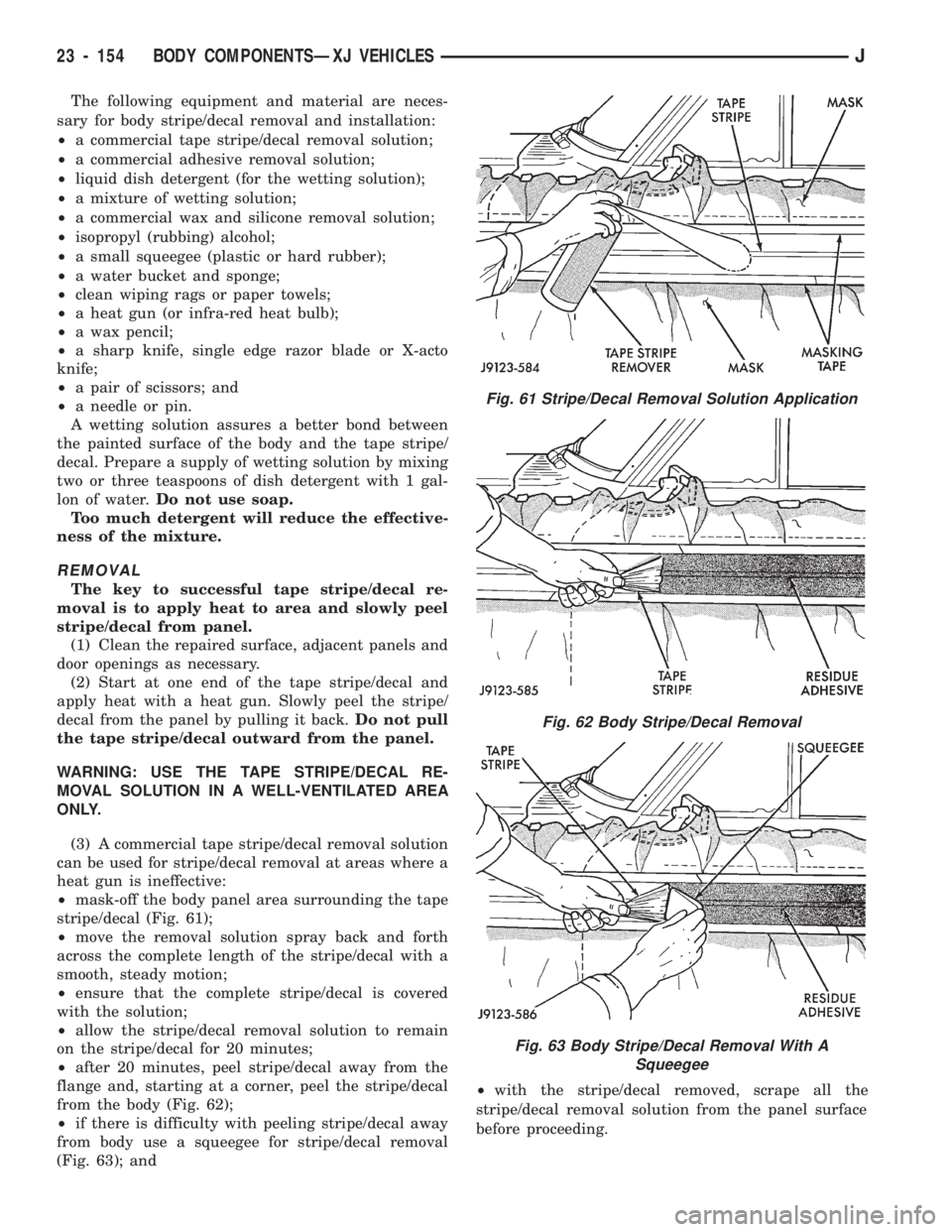
(3) A commercial tape stripe/decal removal solution
can be used for stripe/decal removal at areas where a
heat gun is ineffective:
²mask-off the body panel area surrounding the tape
stripe/decal (Fig. 61);
²move the removal solution spray back and forth
across the complete length of the stripe/decal with a
smooth, steady motion;
²ensure that the complete stripe/decal is covered
with the solution;
²allow the stripe/decal removal solution to remain
on the stripe/decal for 20 minutes;
²after 20 minutes, peel stripe/decal away from the
flange and, starting at a corner, peel the stripe/decal
from the body (Fig. 62);
²if there is difficulty with peeling stripe/decal away
from body use a squeegee for stripe/decal removal
(Fig. 63); and²with the stripe/decal removed, scrape all the
stripe/decal removal solution from the panel surface
before proceeding.
Fig. 61 Stripe/Decal Removal Solution Application
Fig. 62 Body Stripe/Decal Removal
Fig. 63 Body Stripe/Decal Removal With A
Squeegee
23 - 154 BODY COMPONENTSÐXJ VEHICLESJ
Page 1625 of 1784
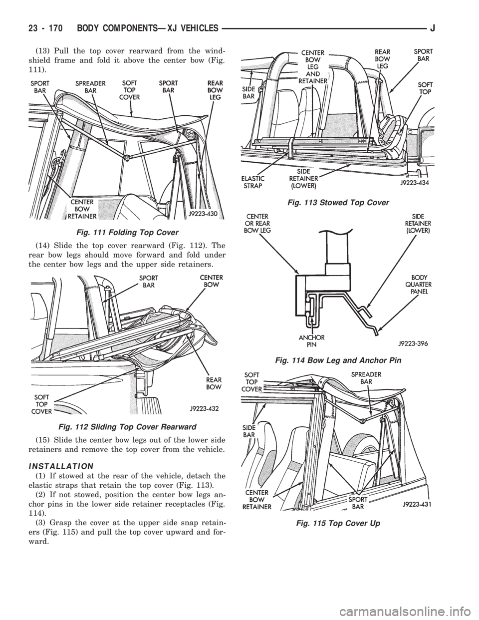
(13) Pull the top cover rearward from the wind-
shield frame and fold it above the center bow (Fig.
111).
(14) Slide the top cover rearward (Fig. 112). The
rear bow legs should move forward and fold under
the center bow legs and the upper side retainers.
(15) Slide the center bow legs out of the lower side
retainers and remove the top cover from the vehicle.
INSTALLATION
(1) If stowed at the rear of the vehicle, detach the
elastic straps that retain the top cover (Fig. 113).
(2) If not stowed, position the center bow legs an-
chor pins in the lower side retainer receptacles (Fig.
114).
(3) Grasp the cover at the upper side snap retain-
ers (Fig. 115) and pull the top cover upward and for-
ward.
Fig. 111 Folding Top Cover
Fig. 112 Sliding Top Cover Rearward
Fig. 113 Stowed Top Cover
Fig. 114 Bow Leg and Anchor Pin
Fig. 115 Top Cover Up
23 - 170 BODY COMPONENTSÐXJ VEHICLESJ
Page 1626 of 1784
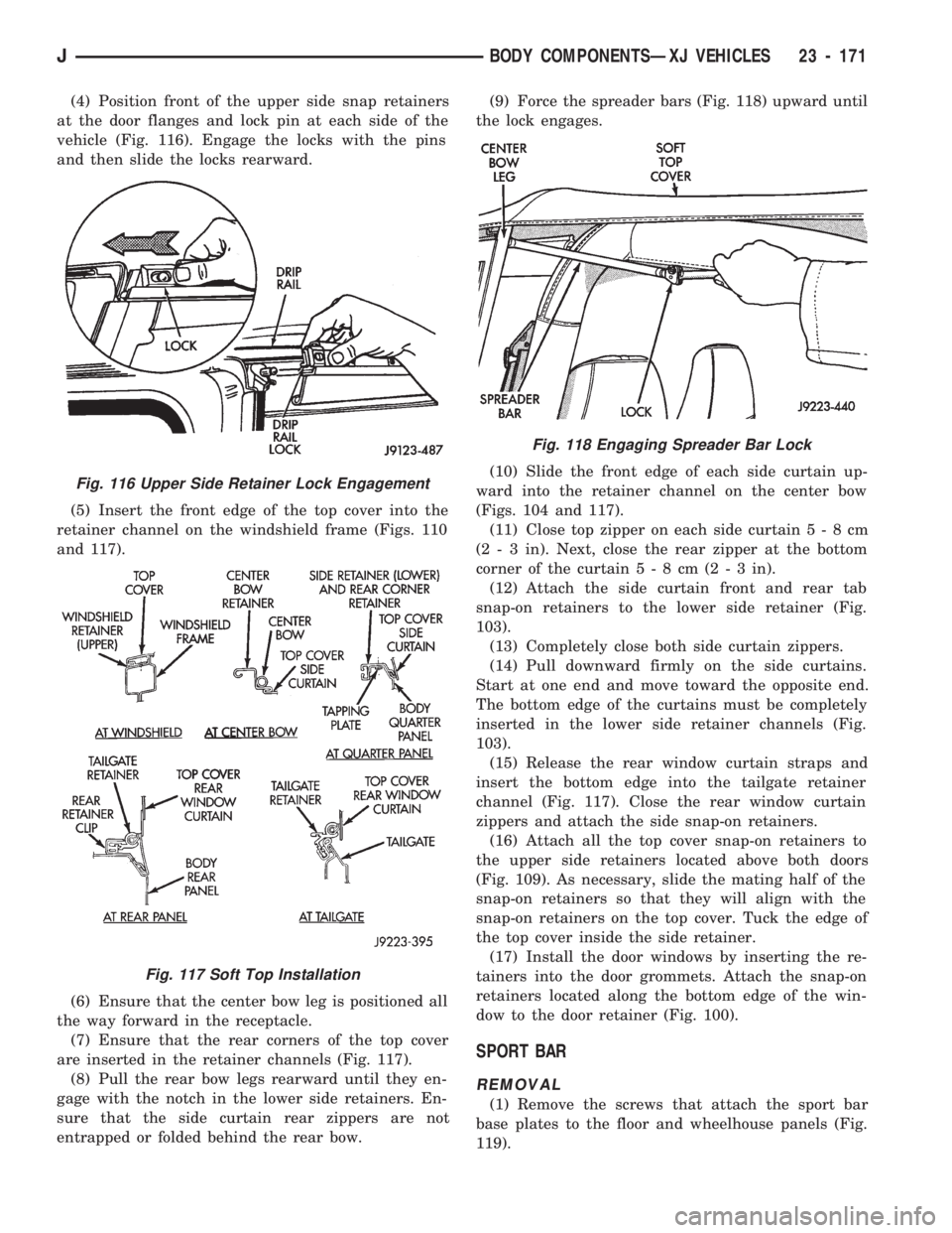
(4) Position front of the upper side snap retainers
at the door flanges and lock pin at each side of the
vehicle (Fig. 116). Engage the locks with the pins
and then slide the locks rearward.
(5) Insert the front edge of the top cover into the
retainer channel on the windshield frame (Figs. 110
and 117).
(6) Ensure that the center bow leg is positioned all
the way forward in the receptacle.
(7) Ensure that the rear corners of the top cover
are inserted in the retainer channels (Fig. 117).
(8) Pull the rear bow legs rearward until they en-
gage with the notch in the lower side retainers. En-
sure that the side curtain rear zippers are not
entrapped or folded behind the rear bow.(9) Force the spreader bars (Fig. 118) upward until
the lock engages.
(10) Slide the front edge of each side curtain up-
ward into the retainer channel on the center bow
(Figs. 104 and 117).
(11) Close top zipper on each side curtain5-8cm
(2 - 3 in). Next, close the rear zipper at the bottom
corner of the curtain5-8cm(2-3in).
(12) Attach the side curtain front and rear tab
snap-on retainers to the lower side retainer (Fig.
103).
(13) Completely close both side curtain zippers.
(14) Pull downward firmly on the side curtains.
Start at one end and move toward the opposite end.
The bottom edge of the curtains must be completely
inserted in the lower side retainer channels (Fig.
103).
(15) Release the rear window curtain straps and
insert the bottom edge into the tailgate retainer
channel (Fig. 117). Close the rear window curtain
zippers and attach the side snap-on retainers.
(16) Attach all the top cover snap-on retainers to
the upper side retainers located above both doors
(Fig. 109). As necessary, slide the mating half of the
snap-on retainers so that they will align with the
snap-on retainers on the top cover. Tuck the edge of
the top cover inside the side retainer.
(17) Install the door windows by inserting the re-
tainers into the door grommets. Attach the snap-on
retainers located along the bottom edge of the win-
dow to the door retainer (Fig. 100).
SPORT BAR
REMOVAL
(1) Remove the screws that attach the sport bar
base plates to the floor and wheelhouse panels (Fig.
119).
Fig. 116 Upper Side Retainer Lock Engagement
Fig. 117 Soft Top Installation
Fig. 118 Engaging Spreader Bar Lock
JBODY COMPONENTSÐXJ VEHICLES 23 - 171