1994 JEEP CHEROKEE tow
[x] Cancel search: towPage 1146 of 1784
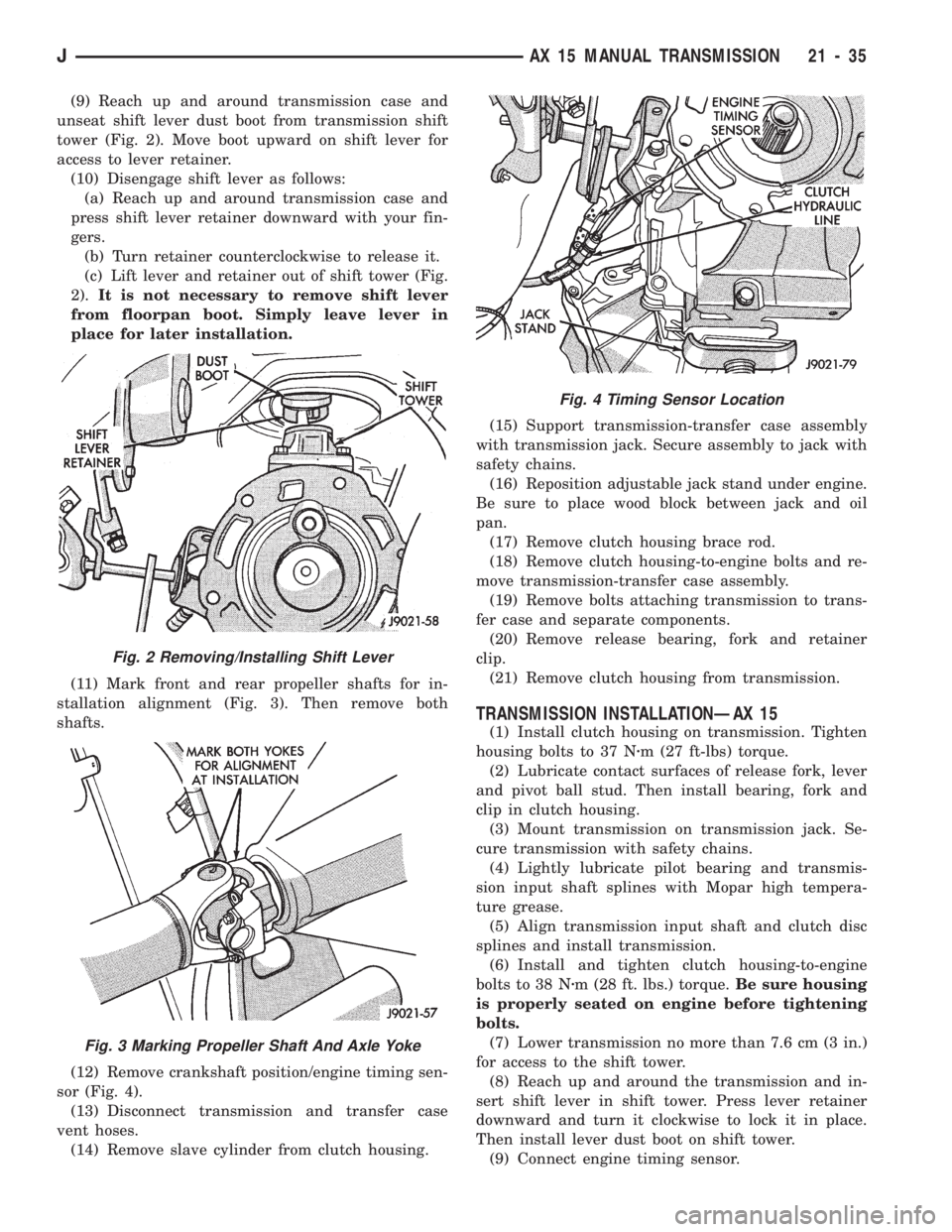
(9) Reach up and around transmission case and
unseat shift lever dust boot from transmission shift
tower (Fig. 2). Move boot upward on shift lever for
access to lever retainer.
(10) Disengage shift lever as follows:
(a) Reach up and around transmission case and
press shift lever retainer downward with your fin-
gers.
(b) Turn retainer counterclockwise to release it.
(c) Lift lever and retainer out of shift tower (Fig.
2).It is not necessary to remove shift lever
from floorpan boot. Simply leave lever in
place for later installation.
(11) Mark front and rear propeller shafts for in-
stallation alignment (Fig. 3). Then remove both
shafts.
(12) Remove crankshaft position/engine timing sen-
sor (Fig. 4).
(13) Disconnect transmission and transfer case
vent hoses.
(14) Remove slave cylinder from clutch housing.(15) Support transmission-transfer case assembly
with transmission jack. Secure assembly to jack with
safety chains.
(16) Reposition adjustable jack stand under engine.
Be sure to place wood block between jack and oil
pan.
(17) Remove clutch housing brace rod.
(18) Remove clutch housing-to-engine bolts and re-
move transmission-transfer case assembly.
(19) Remove bolts attaching transmission to trans-
fer case and separate components.
(20) Remove release bearing, fork and retainer
clip.
(21) Remove clutch housing from transmission.
TRANSMISSION INSTALLATIONÐAX 15
(1) Install clutch housing on transmission. Tighten
housing bolts to 37 Nzm (27 ft-lbs) torque.
(2) Lubricate contact surfaces of release fork, lever
and pivot ball stud. Then install bearing, fork and
clip in clutch housing.
(3) Mount transmission on transmission jack. Se-
cure transmission with safety chains.
(4) Lightly lubricate pilot bearing and transmis-
sion input shaft splines with Mopar high tempera-
ture grease.
(5) Align transmission input shaft and clutch disc
splines and install transmission.
(6) Install and tighten clutch housing-to-engine
bolts to 38 Nzm (28 ft. lbs.) torque.Be sure housing
is properly seated on engine before tightening
bolts.
(7) Lower transmission no more than 7.6 cm (3 in.)
for access to the shift tower.
(8) Reach up and around the transmission and in-
sert shift lever in shift tower. Press lever retainer
downward and turn it clockwise to lock it in place.
Then install lever dust boot on shift tower.
(9) Connect engine timing sensor.
Fig. 2 Removing/Installing Shift Lever
Fig. 3 Marking Propeller Shaft And Axle Yoke
Fig. 4 Timing Sensor Location
JAX 15 MANUAL TRANSMISSION 21 - 35
Page 1147 of 1784
(10) Remove jack from under transmission and
mount transfer case on jack.
(11) Align transfer case and transmission shafts
and install transfer case. Tighten transfer case-to-
transmission nuts/bolts to 35 Nzm (26 ft. lbs.) torque.
(12) Move jack stand from under engine and repo-
sition it under transmission. Then remove transmis-
sion jack.
(13) Connect transfer case vacuum hoses and link-
age. Check and adjust linkage if necessary.
(14) Connect transmission and transfer case vent
hoses and backup light switch wires.
(15) Install clutch sleeve cylinder.
(16) Connect vehicle speed sensor and wires.
(17) On XJ, install rear crossmember and attach
cushion and bracket. Tighten crossmember-to-frame
bolts to 41 Nzm (30 ft. lbs.) torque. Tighten transmis-
sion-to-rear cushion and bracket bolts/nuts to 45 Nzm
(33 ft. lbs.) torque.
(18) On YJ, install rear cushion and bracket and
skid plate. Tighten attaching bolts/nuts to indicated
torque (Fig. 1).
(19) Align and install front/rear propeller shafts.
Tighten shaft U-joint clamp bolts to 19 Nzm (170 in.
lbs.) torque.
(20) On XJ, install skid plate if removed. Tighten
bolts to 42 Nzm (31 ft. lbs.) torque. Tighten stud nuts
to 17 Nzm (150 in. lbs.) torque.
(21) Top off transmission and transfer lubricant
levels.
(22) Remove supports and lower vehicle.
TRANSMISSION DISASSEMBLY AND OVERHAUL
ADAPTER/EXTENSION HOUSING REMOVAL
(1) Remove release bearing, fork, retainer clip and
clutch housing from transmission. Also remove shift
lever if not previously removed.
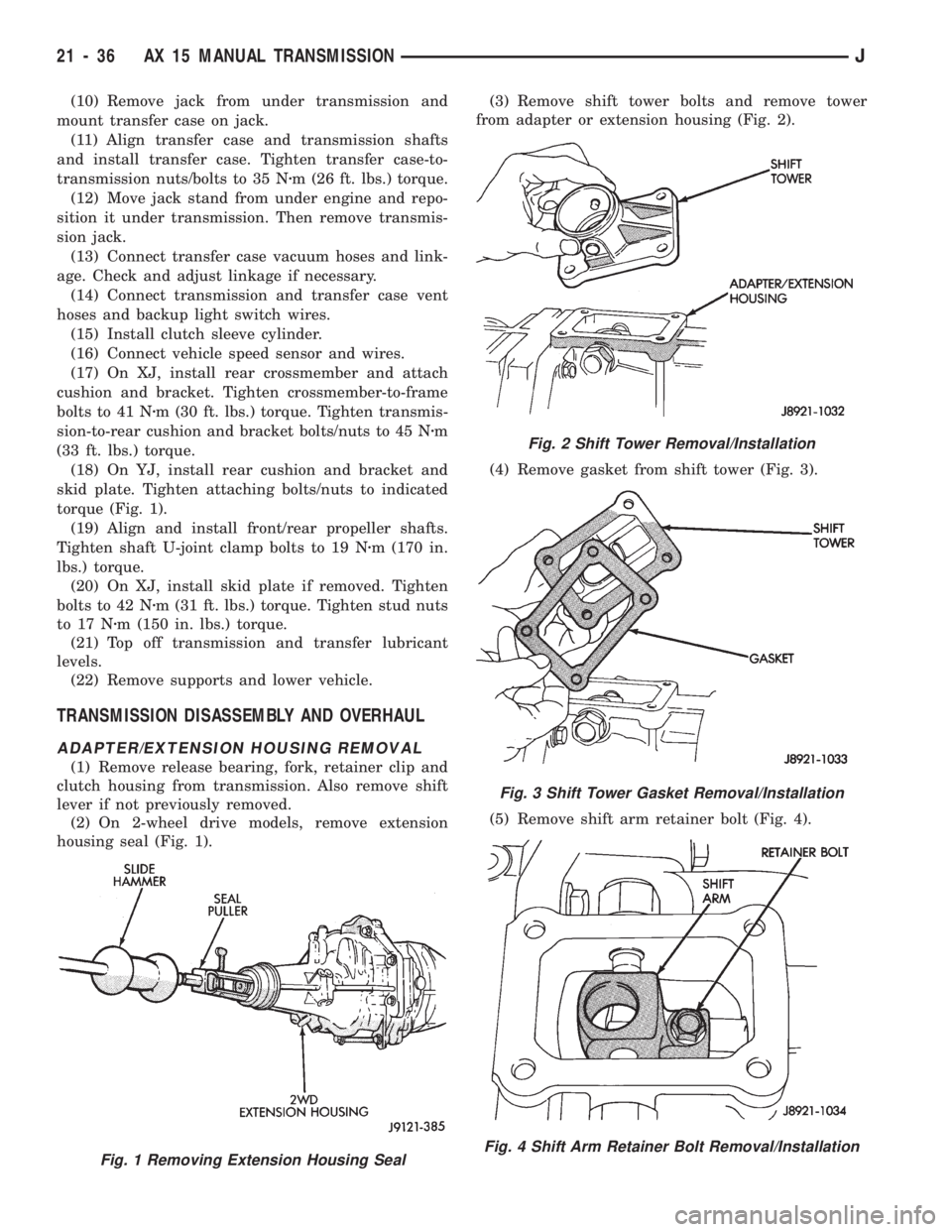
(2) On 2-wheel drive models, remove extension
housing seal (Fig. 1).(3) Remove shift tower bolts and remove tower
from adapter or extension housing (Fig. 2).
(4) Remove gasket from shift tower (Fig. 3).
(5) Remove shift arm retainer bolt (Fig. 4).
Fig. 1 Removing Extension Housing Seal
Fig. 2 Shift Tower Removal/Installation
Fig. 3 Shift Tower Gasket Removal/Installation
Fig. 4 Shift Arm Retainer Bolt Removal/Installation
21 - 36 AX 15 MANUAL TRANSMISSIONJ
Page 1161 of 1784
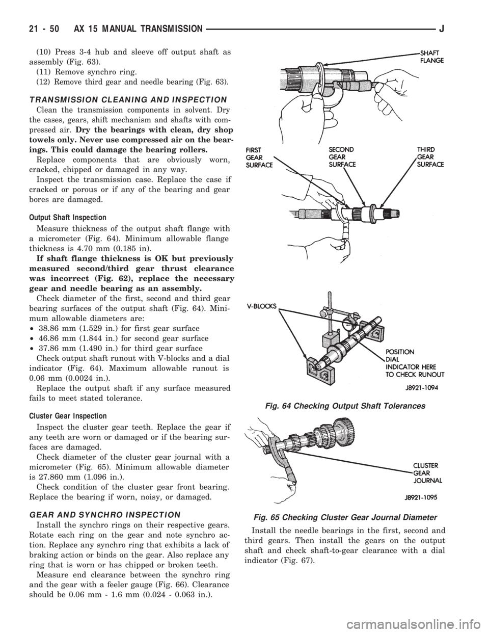
(10) Press 3-4 hub and sleeve off output shaft as
assembly (Fig. 63).
(11) Remove synchro ring.
(12) Remove third gear and needle bearing (Fig. 63).
TRANSMISSION CLEANING AND INSPECTION
Clean the transmission components in solvent. Dry
the cases, gears, shift mechanism and shafts with com-
pressed air.Dry the bearings with clean, dry shop
towels only. Never use compressed air on the bear-
ings. This could damage the bearing rollers.
Replace components that are obviously worn,
cracked, chipped or damaged in any way.
Inspect the transmission case. Replace the case if
cracked or porous or if any of the bearing and gear
bores are damaged.
Output Shaft Inspection
Measure thickness of the output shaft flange with
a micrometer (Fig. 64). Minimum allowable flange
thickness is 4.70 mm (0.185 in).
If shaft flange thickness is OK but previously
measured second/third gear thrust clearance
was incorrect (Fig. 62), replace the necessary
gear and needle bearing as an assembly.
Check diameter of the first, second and third gear
bearing surfaces of the output shaft (Fig. 64). Mini-
mum allowable diameters are:
²38.86 mm (1.529 in.) for first gear surface
²46.86 mm (1.844 in.) for second gear surface
²37.86 mm (1.490 in.) for third gear surface
Check output shaft runout with V-blocks and a dial
indicator (Fig. 64). Maximum allowable runout is
0.06 mm (0.0024 in.).
Replace the output shaft if any surface measured
fails to meet stated tolerance.
Cluster Gear Inspection
Inspect the cluster gear teeth. Replace the gear if
any teeth are worn or damaged or if the bearing sur-
faces are damaged.
Check diameter of the cluster gear journal with a
micrometer (Fig. 65). Minimum allowable diameter
is 27.860 mm (1.096 in.).
Check condition of the cluster gear front bearing.
Replace the bearing if worn, noisy, or damaged.
GEAR AND SYNCHRO INSPECTION
Install the synchro rings on their respective gears.
Rotate each ring on the gear and note synchro ac-
tion. Replace any synchro ring that exhibits a lack of
braking action or binds on the gear. Also replace any
ring that is worn or has chipped or broken teeth.
Measure end clearance between the synchro ring
and the gear with a feeler gauge (Fig. 66). Clearance
should be 0.06 mm - 1.6 mm (0.024 - 0.063 in.).Install the needle bearings in the first, second and
third gears. Then install the gears on the output
shaft and check shaft-to-gear clearance with a dial
indicator (Fig. 67).
Fig. 64 Checking Output Shaft Tolerances
Fig. 65 Checking Cluster Gear Journal Diameter
21 - 50 AX 15 MANUAL TRANSMISSIONJ
Page 1176 of 1784
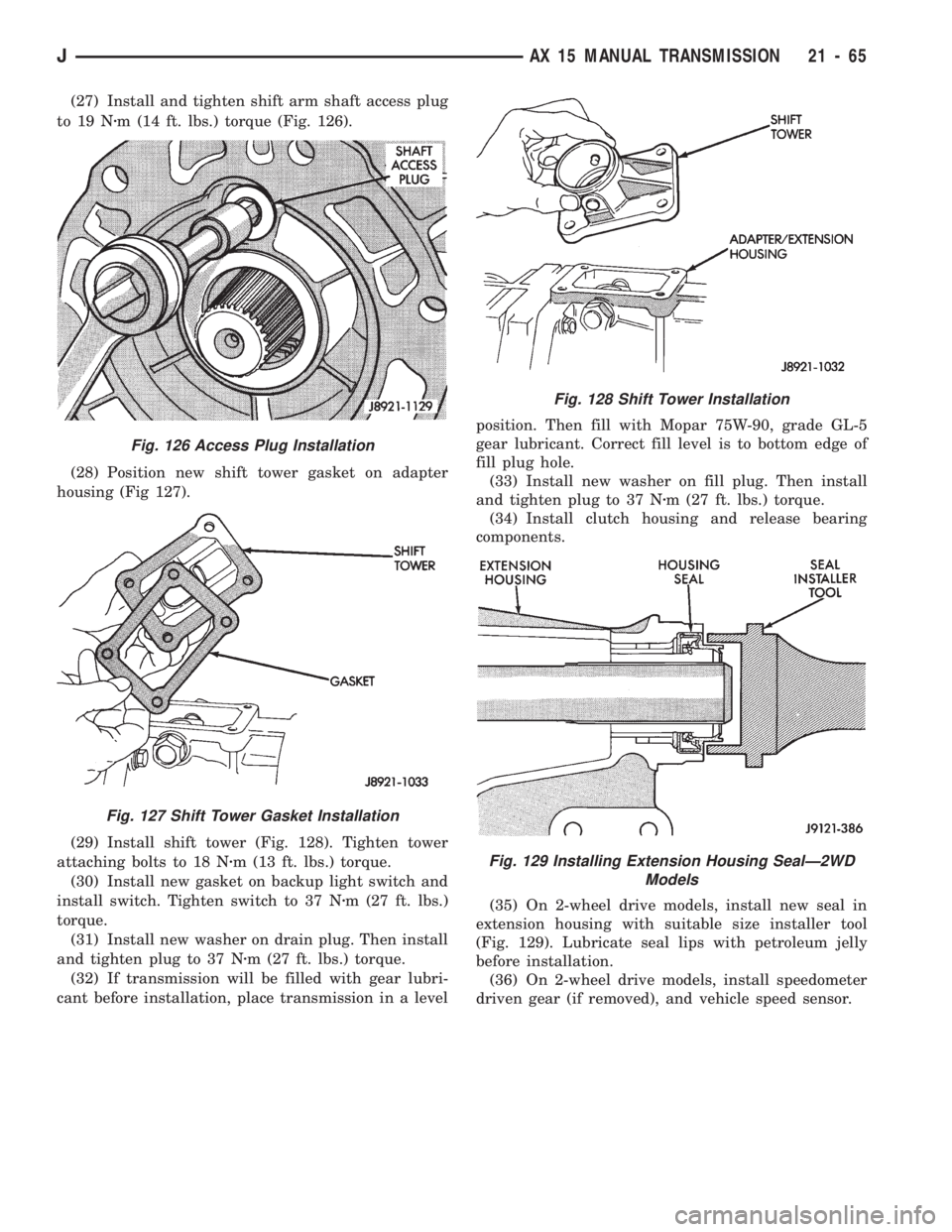
(27) Install and tighten shift arm shaft access plug
to 19 Nzm (14 ft. lbs.) torque (Fig. 126).
(28) Position new shift tower gasket on adapter
housing (Fig 127).
(29) Install shift tower (Fig. 128). Tighten tower
attaching bolts to 18 Nzm (13 ft. lbs.) torque.
(30) Install new gasket on backup light switch and
install switch. Tighten switch to 37 Nzm (27 ft. lbs.)
torque.
(31) Install new washer on drain plug. Then install
and tighten plug to 37 Nzm (27 ft. lbs.) torque.
(32) If transmission will be filled with gear lubri-
cant before installation, place transmission in a levelposition. Then fill with Mopar 75W-90, grade GL-5
gear lubricant. Correct fill level is to bottom edge of
fill plug hole.
(33) Install new washer on fill plug. Then install
and tighten plug to 37 Nzm (27 ft. lbs.) torque.
(34) Install clutch housing and release bearing
components.
(35) On 2-wheel drive models, install new seal in
extension housing with suitable size installer tool
(Fig. 129). Lubricate seal lips with petroleum jelly
before installation.
(36) On 2-wheel drive models, install speedometer
driven gear (if removed), and vehicle speed sensor.
Fig. 126 Access Plug Installation
Fig. 127 Shift Tower Gasket Installation
Fig. 128 Shift Tower Installation
Fig. 129 Installing Extension Housing SealÐ2WD
Models
JAX 15 MANUAL TRANSMISSION 21 - 65
Page 1213 of 1784
GOVERNOR DISASSEMBLY
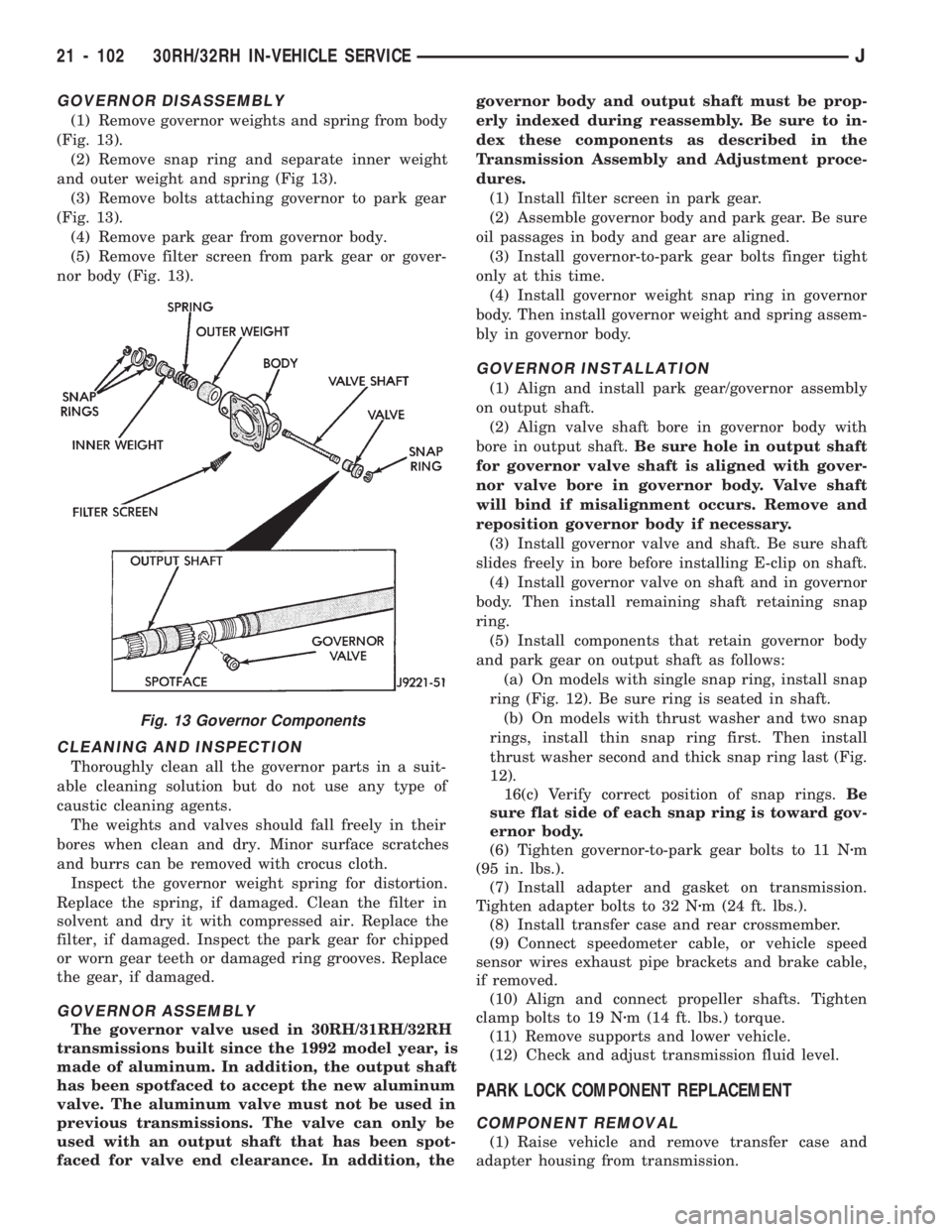
(1) Remove governor weights and spring from body
(Fig. 13).
(2) Remove snap ring and separate inner weight
and outer weight and spring (Fig 13).
(3) Remove bolts attaching governor to park gear
(Fig. 13).
(4) Remove park gear from governor body.
(5) Remove filter screen from park gear or gover-
nor body (Fig. 13).
CLEANING AND INSPECTION
Thoroughly clean all the governor parts in a suit-
able cleaning solution but do not use any type of
caustic cleaning agents.
The weights and valves should fall freely in their
bores when clean and dry. Minor surface scratches
and burrs can be removed with crocus cloth.
Inspect the governor weight spring for distortion.
Replace the spring, if damaged. Clean the filter in
solvent and dry it with compressed air. Replace the
filter, if damaged. Inspect the park gear for chipped
or worn gear teeth or damaged ring grooves. Replace
the gear, if damaged.
GOVERNOR ASSEMBLY
The governor valve used in 30RH/31RH/32RH
transmissions built since the 1992 model year, is
made of aluminum. In addition, the output shaft
has been spotfaced to accept the new aluminum
valve. The aluminum valve must not be used in
previous transmissions. The valve can only be
used with an output shaft that has been spot-
faced for valve end clearance. In addition, thegovernor body and output shaft must be prop-
erly indexed during reassembly. Be sure to in-
dex these components as described in the
Transmission Assembly and Adjustment proce-
dures.
(1) Install filter screen in park gear.
(2) Assemble governor body and park gear. Be sure
oil passages in body and gear are aligned.
(3) Install governor-to-park gear bolts finger tight
only at this time.
(4) Install governor weight snap ring in governor
body. Then install governor weight and spring assem-
bly in governor body.
GOVERNOR INSTALLATION
(1) Align and install park gear/governor assembly
on output shaft.
(2) Align valve shaft bore in governor body with
bore in output shaft.Be sure hole in output shaft
for governor valve shaft is aligned with gover-
nor valve bore in governor body. Valve shaft
will bind if misalignment occurs. Remove and
reposition governor body if necessary.
(3) Install governor valve and shaft. Be sure shaft
slides freely in bore before installing E-clip on shaft.
(4) Install governor valve on shaft and in governor
body. Then install remaining shaft retaining snap
ring.
(5) Install components that retain governor body
and park gear on output shaft as follows:
(a) On models with single snap ring, install snap
ring (Fig. 12). Be sure ring is seated in shaft.
(b) On models with thrust washer and two snap
rings, install thin snap ring first. Then install
thrust washer second and thick snap ring last (Fig.
12).
16(c) Verify correct position of snap rings.Be
sure flat side of each snap ring is toward gov-
ernor body.
(6) Tighten governor-to-park gear bolts to 11 Nzm
(95 in. lbs.).
(7) Install adapter and gasket on transmission.
Tighten adapter bolts to 32 Nzm (24 ft. lbs.).
(8) Install transfer case and rear crossmember.
(9) Connect speedometer cable, or vehicle speed
sensor wires exhaust pipe brackets and brake cable,
if removed.
(10) Align and connect propeller shafts. Tighten
clamp bolts to 19 Nzm (14 ft. lbs.) torque.
(11) Remove supports and lower vehicle.
(12) Check and adjust transmission fluid level.
PARK LOCK COMPONENT REPLACEMENT
COMPONENT REMOVAL
(1) Raise vehicle and remove transfer case and
adapter housing from transmission.
Fig. 13 Governor Components
21 - 102 30RH/32RH IN-VEHICLE SERVICEJ
Page 1221 of 1784
(1) Lubricate converter drive hub and pump seal
with Mopar ATF Plus, or Dexron II transmission
fluid. Then install converter. Turn converter back
and forth to align drive slots in converter hub with
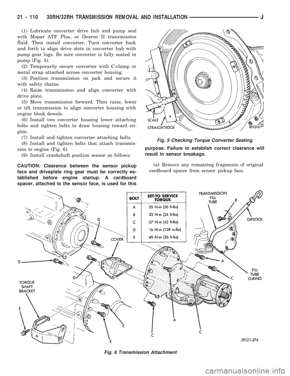
pump gear lugs. Be sure converter is fully seated in
pump (Fig. 5).
(2) Temporarily secure converter with C-clamp or
metal strap attached across converter housing.
(3) Position transmission on jack and secure it
with safety chains.
(4) Raise transmission and align converter with
drive plate.
(5) Move transmission forward. Then raise, lower
or tilt transmission to align converter housing with
engine block dowels.
(6) Install two converter housing lower attaching
bolts and tighten bolts to draw housing toward en-
gine.
(7) Install and tighten converter attaching bolts.
(8) Install and tighten bolts that attach transmis-
sion to engine (Fig. 6).
(9) Install crankshaft position sensor as follows:
CAUTION: Clearance between the sensor pickup
face and driveplate ring gear must be correctly es-
tablished before engine startup. A cardboard
spacer, attached to the sensor face, is used for thispurpose. Failure to establish correct clearance will
result in sensor breakage.
(a) Remove any remaining fragments of original
cardboard spacer from sensor pickup face.
Fig. 5 Checking Torque Converter Seating
Fig. 6 Transmission Attachment
21 - 110 30RH/32RH TRANSMISSION REMOVAL AND INSTALLATIONJ
Page 1229 of 1784
OVERHAUL SERVICE INFORMATION
Inspect the transmission bushings during overhaul.
Bushing condition is important as severely worn, or
scored bushings contribute to low pressures, clutch
slip and accelerated wear of other components.How-
ever, do not replace bushings as a matter of
course. Replace bushings only when they are
actually worn, or scored.
Use recommended tools to replace bushings. The
tools are sized and designed to remove, install and
seat bushings correctly. The bushing replacement
tools are included in Bushing Tool Set C-3887-B. The
tool set is manufactured by Miller Tool Co. and is
available through the dealer tool program.
Pre-sized service bushings are available for replace-
ment purposes. Only the sun gear bushings are not
serviced. Low cost of the sun gear assembly makes it
easier to simply replace the gear and bushings as an
assembly.
Heli-Coil inserts are recommended for repairing
damaged, stripped or worn threads in aluminum
parts. These inserts are available from most automo-
tive jobbers. Stainless steel inserts are preferred.
The use of crocus cloth is permissible where neces-
sary. When used on valves, use care to avoid round-
ing off sharp edges. Sharp edges are vital as they
prevent foreign matter from getting between the
valve and valve bore.
Do not reuse oil seals, gaskets, seal rings, or O-
rings during overhaul. Replace these parts as a mat-
ter of course. Also do not reuse snap rings or E-clips
that are bent or distorted. Replace these parts as
well.
Lubricate transmission parts with Mopar ATF
Plus, Type 7176 transmission fluid during overhaul
and assembly.Use petroleum jelly to hold parts like thrust wash-
ers in place during assembly. Use Ru-Glyde, Door
Eze, or similar products to lubricate piston seals and
O-rings to ease installation. Petroleum jelly can also
be used to prelubricate parts during reassembly if de-
sired.
TRANSMISSION CASE CLEANING AND
INSPECTION
Clean the case in a solvent tank. Flush the case
bores and fluid passages thoroughly with solvent.
Dry the case and all fluid passages with compressed
air. Be sure all solvent is removed from the case and
that all fluid passages are clear.
Do not use shop towels or rags to dry the case
(or any other transmission component) unless
they are made from lint-free materials. Lint will
readily adhere to case surfaces and transmission
components and will circulate throughout the
transmission after assembly. A sufficient quan-
tity of lint can block fluid passages and interfere
with valve body operation.
Inspect the case for cracks, porous spots, worn
bores, or damaged threads. Damaged threads can be
repaired with Helicoil thread inserts. However, the
case will have to be replaced if it exhibits any type of
damage or wear.
Lubricate the front band adjusting screw threads
with petroleum jelly and thread the screw part-way
into the case. Be sure the screw turns freely.
Remount the case in a repair stand after cleaning
and inspection.
OVERRUNNING CLUTCHÐLOW-REVERSE
DRUMÐREAR SUPPORT OVERHAUL
DISASSEMBLING OVERRUNNING CLUTCH/
LOW-REVERSE DRUM
If the clutch assembly came out with the low-re-
verse drum, thread two clutch cam bolts into the
cam. Then lift the cam out of the drum with the bolts
(Fig. 30). Rotate the cam back and forth to ease re-
moval if necessary. Remove the clutch roller and
spring assembly from the race afterward.
CLEANING AND INSPECTION
Clean the overrunning clutch assembly, clutch
cam, low-reverse drum and rear support in solvent.
Dry them with compressed air after cleaning.
Inspect condition of each clutch part after cleaning.
Replace the overrunning clutch roller and spring as-
sembly if any rollers or springs are worn or dam-
aged, or if the roller cage is distorted, or damaged.
Replace the cam if worn, cracked or damaged.
Replace the low-reverse drum if the clutch race,
roller surface or inside diameter is scored, worn or
damaged.Do not remove the clutch race from the
Fig. 29 Compressing Rear Servo Spring
21 - 118 30RH/32RH TRANSMISSION OVERHAULJ
Page 1237 of 1784
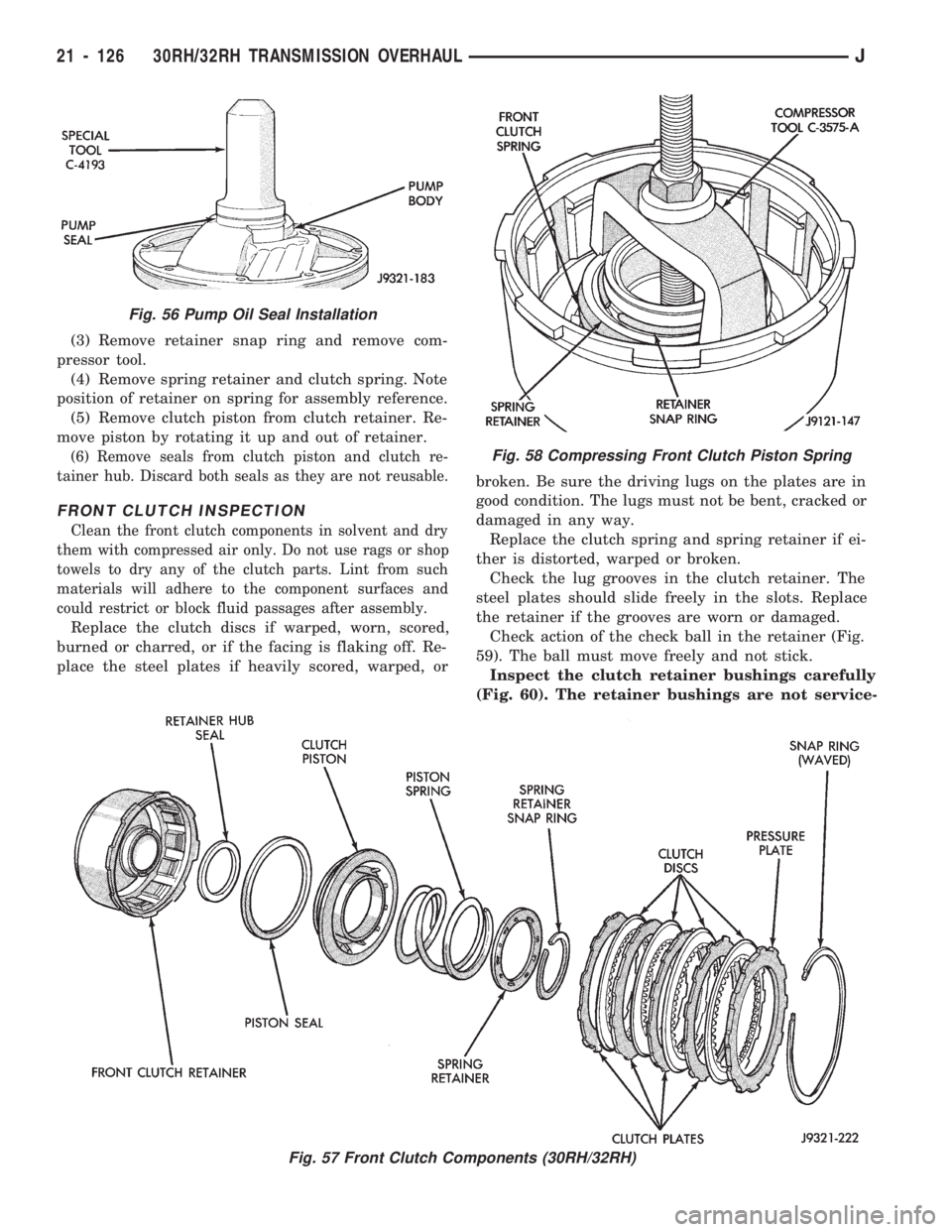
(3) Remove retainer snap ring and remove com-
pressor tool.
(4) Remove spring retainer and clutch spring. Note
position of retainer on spring for assembly reference.
(5) Remove clutch piston from clutch retainer. Re-
move piston by rotating it up and out of retainer.
(6) Remove seals from clutch piston and clutch re-
tainer hub. Discard both seals as they are not reusable.
FRONT CLUTCH INSPECTION
Clean the front clutch components in solvent and dry
them with compressed air only. Do not use rags or shop
towels to dry any of the clutch parts. Lint from such
materials will adhere to the component surfaces and
could restrict or block fluid passages after assembly.
Replace the clutch discs if warped, worn, scored,
burned or charred, or if the facing is flaking off. Re-
place the steel plates if heavily scored, warped, orbroken. Be sure the driving lugs on the plates are in
good condition. The lugs must not be bent, cracked or
damaged in any way.
Replace the clutch spring and spring retainer if ei-
ther is distorted, warped or broken.
Check the lug grooves in the clutch retainer. The
steel plates should slide freely in the slots. Replace
the retainer if the grooves are worn or damaged.
Check action of the check ball in the retainer (Fig.
59). The ball must move freely and not stick.
Inspect the clutch retainer bushings carefully
(Fig. 60). The retainer bushings are not service-
Fig. 56 Pump Oil Seal Installation
Fig. 57 Front Clutch Components (30RH/32RH)
Fig. 58 Compressing Front Clutch Piston Spring
21 - 126 30RH/32RH TRANSMISSION OVERHAULJ