Page 1315 of 1784
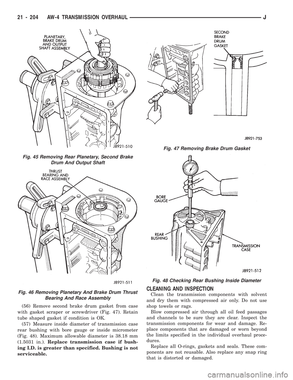
(56) Remove second brake drum gasket from case
with gasket scraper or screwdriver (Fig. 47). Retain
tube shaped gasket if condition is OK.
(57) Measure inside diameter of transmission case
rear bushing with bore gauge or inside micrometer
(Fig. 48). Maximum allowable diameter is 38.18 mm
(1.5031 in.).Replace transmission case if bush-
ing I.D. is greater than specified. Bushing is not
serviceable.
CLEANING AND INSPECTION
Clean the transmission components with solvent
and dry them with compressed air only. Do not use
shop towels or rags.
Blow compressed air through all oil feed passages
and channels to be sure they are clear. Inspect the
transmission components for wear and damage. Re-
place components that are damaged or worn beyond
the limits specified in the individual overhaul proce-
dures.
Replace all O-rings, gaskets and seals. These com-
ponents are not reusable. Also replace any snap ring
that is distorted or damaged.
Fig. 45 Removing Rear Planetary, Second Brake
Drum And Output Shaft
Fig. 46 Removing Planetary And Brake Drum Thrust
Bearing And Race Assembly
Fig. 47 Removing Brake Drum Gasket
Fig. 48 Checking Rear Bushing Inside Diameter
21 - 204 AW-4 TRANSMISSION OVERHAULJ
Page 1337 of 1784
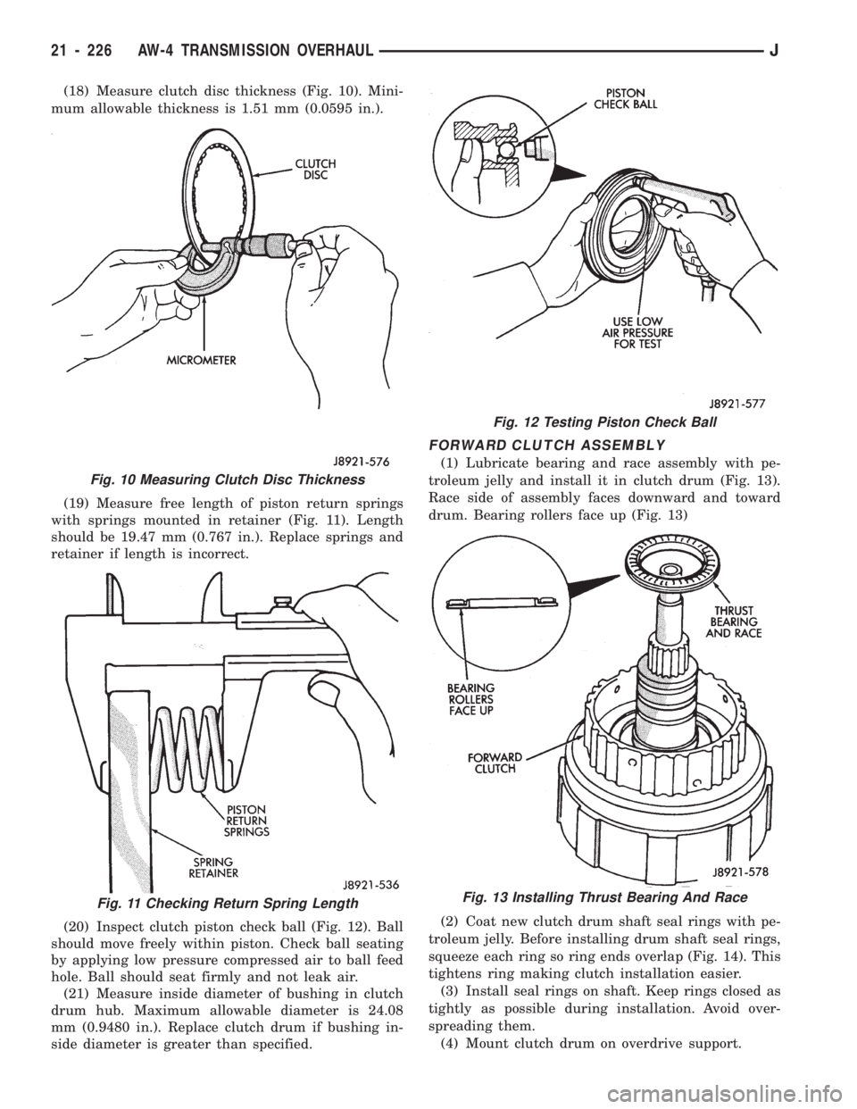
(18) Measure clutch disc thickness (Fig. 10). Mini-
mum allowable thickness is 1.51 mm (0.0595 in.).
(19) Measure free length of piston return springs
with springs mounted in retainer (Fig. 11). Length
should be 19.47 mm (0.767 in.). Replace springs and
retainer if length is incorrect.
(20) Inspect clutch piston check ball (Fig. 12). Ball
should move freely within piston. Check ball seating
by applying low pressure compressed air to ball feed
hole. Ball should seat firmly and not leak air.
(21) Measure inside diameter of bushing in clutch
drum hub. Maximum allowable diameter is 24.08
mm (0.9480 in.). Replace clutch drum if bushing in-
side diameter is greater than specified.
FORWARD CLUTCH ASSEMBLY
(1) Lubricate bearing and race assembly with pe-
troleum jelly and install it in clutch drum (Fig. 13).
Race side of assembly faces downward and toward
drum. Bearing rollers face up (Fig. 13)
(2) Coat new clutch drum shaft seal rings with pe-
troleum jelly. Before installing drum shaft seal rings,
squeeze each ring so ring ends overlap (Fig. 14). This
tightens ring making clutch installation easier.
(3) Install seal rings on shaft. Keep rings closed as
tightly as possible during installation. Avoid over-
spreading them.
(4) Mount clutch drum on overdrive support.
Fig. 10 Measuring Clutch Disc Thickness
Fig. 11 Checking Return Spring Length
Fig. 12 Testing Piston Check Ball
Fig. 13 Installing Thrust Bearing And Race
21 - 226 AW-4 TRANSMISSION OVERHAULJ
Page 1355 of 1784
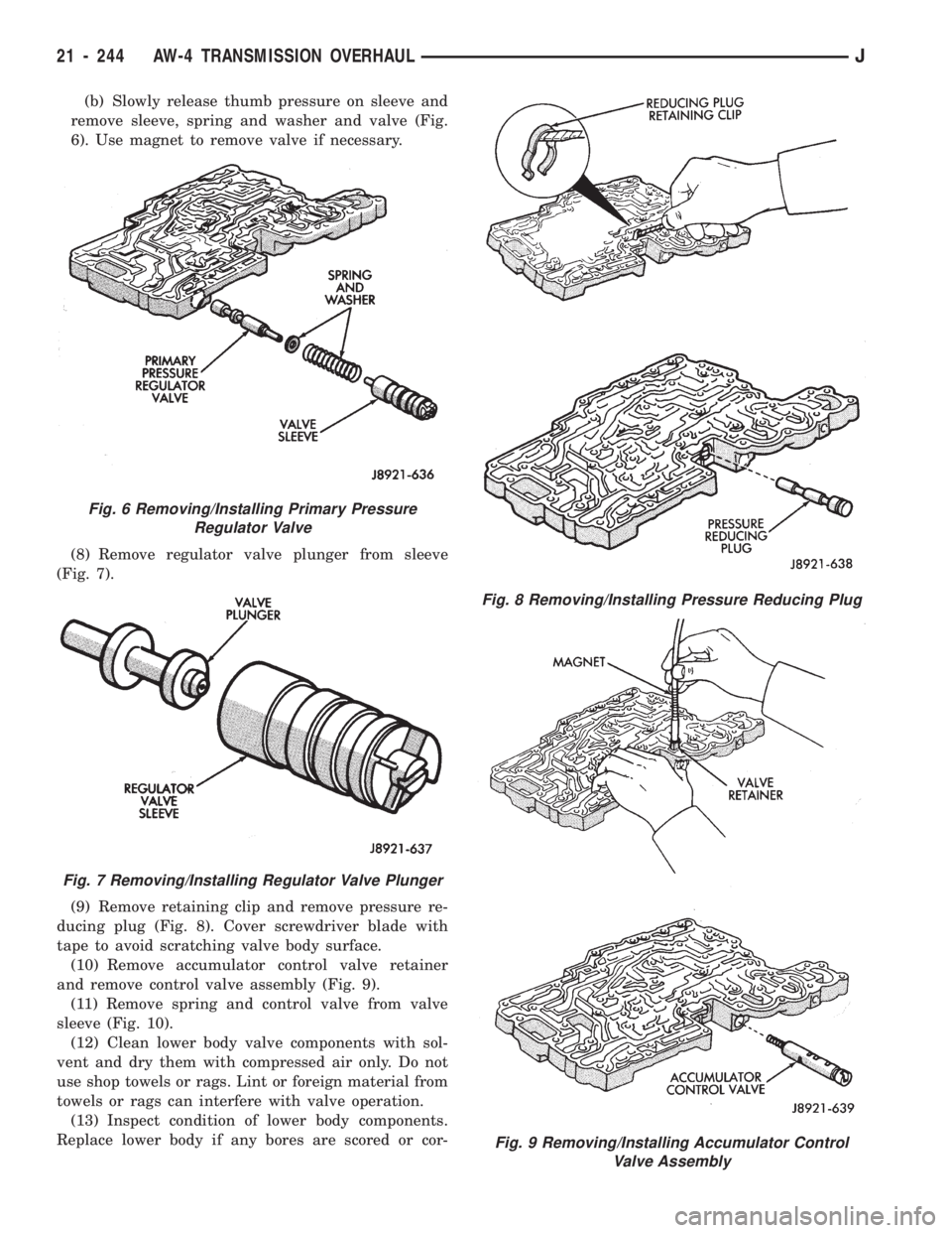
(b) Slowly release thumb pressure on sleeve and
remove sleeve, spring and washer and valve (Fig.
6). Use magnet to remove valve if necessary.
(8) Remove regulator valve plunger from sleeve
(Fig. 7).
(9) Remove retaining clip and remove pressure re-
ducing plug (Fig. 8). Cover screwdriver blade with
tape to avoid scratching valve body surface.
(10) Remove accumulator control valve retainer
and remove control valve assembly (Fig. 9).
(11) Remove spring and control valve from valve
sleeve (Fig. 10).
(12) Clean lower body valve components with sol-
vent and dry them with compressed air only. Do not
use shop towels or rags. Lint or foreign material from
towels or rags can interfere with valve operation.
(13) Inspect condition of lower body components.
Replace lower body if any bores are scored or cor-
Fig. 9 Removing/Installing Accumulator Control
Valve Assembly
Fig. 6 Removing/Installing Primary Pressure
Regulator Valve
Fig. 7 Removing/Installing Regulator Valve Plunger
Fig. 8 Removing/Installing Pressure Reducing Plug
21 - 244 AW-4 TRANSMISSION OVERHAULJ
Page 1358 of 1784
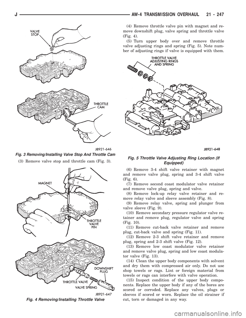
(3) Remove valve stop and throttle cam (Fig. 3).(4) Remove throttle valve pin with magnet and re-
move downshift plug, valve spring and throttle valve
(Fig. 4).
(5) Turn upper body over and remove throttle
valve adjusting rings and spring (Fig. 5). Note num-
ber of adjusting rings if valve is equipped with them.
(6) Remove 3-4 shift valve retainer with magnet
and remove valve plug, spring and 3-4 shift valve
(Fig. 6).
(7) Remove second coast modulator valve retainer
and remove valve plug, spring and valve.
(8) Remove lock-up relay valve retainer and re-
move relay valve and sleeve assembly (Fig. 8).
(9) Remove relay valve, spring and plunger from
valve sleeve (Fig. 9).
(10) Remove secondary pressure regulator valve re-
tainer and remove plug, regulator valve and spring
(Fig. 10).
(11) Remove cut-back valve retainer and remove
plug, cut-back valve and spring (Fig. 11).
(12) Remove 2-3 shift valve retainer and remove
plug, spring and 2-3 shift valve (Fig. 12).
(13) Remove low coast modulator valve retainer
and remove valve plug, spring and low coast modula-
tor valve (Fig. 13).
(14) Clean the upper body components with solvent
and dry them with compressed air only. Do not use
shop towels or rags. Lint or foreign material from
towels or rags can interfere with valve operation.
(15) Inspect condition of the upper body compo-
nents. Replace the upper body if any of the bores are
scored or corroded. Replace any valves, plugs or
sleeves if scored or worn. Replace the oil strainer if
cut, torn or damaged in any way.
Fig. 3 Removing/Installing Valve Stop And Throttle Cam
Fig. 4 Removing/Installing Throttle Valve
Fig. 5 Throttle Valve Adjusting Ring Location (If
Equipped)
JAW-4 TRANSMISSION OVERHAUL 21 - 247
Page 1367 of 1784
(4) Install rear planetary gear, second brake drum
and output shaft as outlined in following steps:
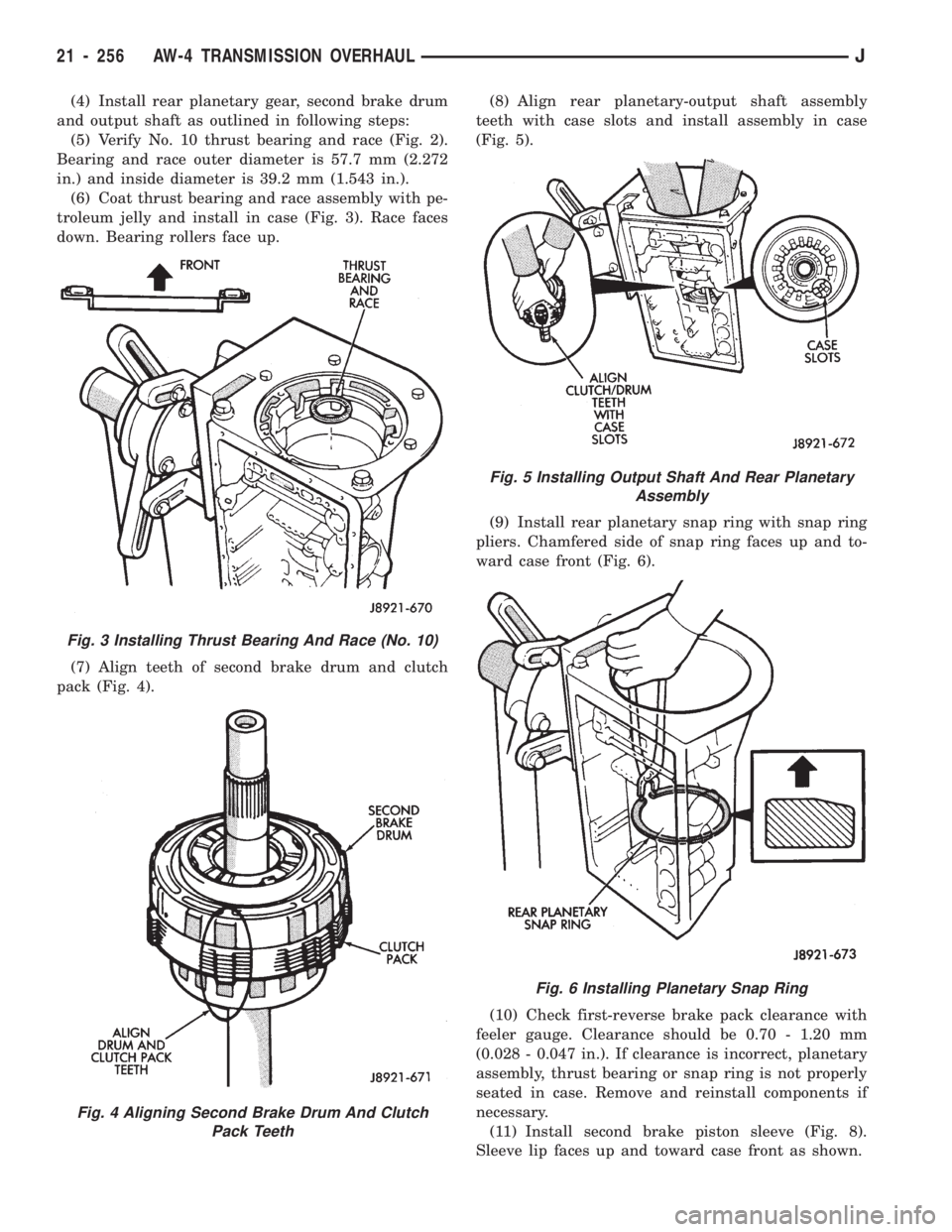
(5) Verify No. 10 thrust bearing and race (Fig. 2).
Bearing and race outer diameter is 57.7 mm (2.272
in.) and inside diameter is 39.2 mm (1.543 in.).
(6) Coat thrust bearing and race assembly with pe-
troleum jelly and install in case (Fig. 3). Race faces
down. Bearing rollers face up.
(7) Align teeth of second brake drum and clutch
pack (Fig. 4).(8) Align rear planetary-output shaft assembly
teeth with case slots and install assembly in case
(Fig. 5).
(9) Install rear planetary snap ring with snap ring
pliers. Chamfered side of snap ring faces up and to-
ward case front (Fig. 6).
(10) Check first-reverse brake pack clearance with
feeler gauge. Clearance should be 0.70 - 1.20 mm
(0.028 - 0.047 in.). If clearance is incorrect, planetary
assembly, thrust bearing or snap ring is not properly
seated in case. Remove and reinstall components if
necessary.
(11) Install second brake piston sleeve (Fig. 8).
Sleeve lip faces up and toward case front as shown.
Fig. 3 Installing Thrust Bearing And Race (No. 10)
Fig. 4 Aligning Second Brake Drum And Clutch
Pack Teeth
Fig. 5 Installing Output Shaft And Rear Planetary
Assembly
Fig. 6 Installing Planetary Snap Ring
21 - 256 AW-4 TRANSMISSION OVERHAULJ
Page 1369 of 1784
(17) Install No. 1 one-way clutch (Fig. 14). Short
flanged side of clutch faces up and toward case front.
(18) Install second brake pack (Fig. 15). Install
disc then plate. Continue installation sequence until
correct number of discs-plates are installed. Use five
discs and five plates.
(19) Install second brake pack retainer with
rounded edge of retainer facing disc.
(20) Install second brake pack snap ring.
(21) Check brake pack clearance with feeler gauge
(Fig. 16). Clearance should be 0.062 - 1.98 mm (0.024
- 0.078 in.). If brake pack clearance is not correct,
brake pack components are not seated. Reassemble
brake pack if necessary.
Fig. 14 Installing No. 1 One-Way Clutch
Fig. 12 Installing Park Rod Bracket
Fig. 13 Checking Park Pawl Engagement
Fig. 15 Installing Second Brake Pack
Fig. 16 Checking Second Brake Pack Clearance
21 - 258 AW-4 TRANSMISSION OVERHAULJ
Page 1370 of 1784
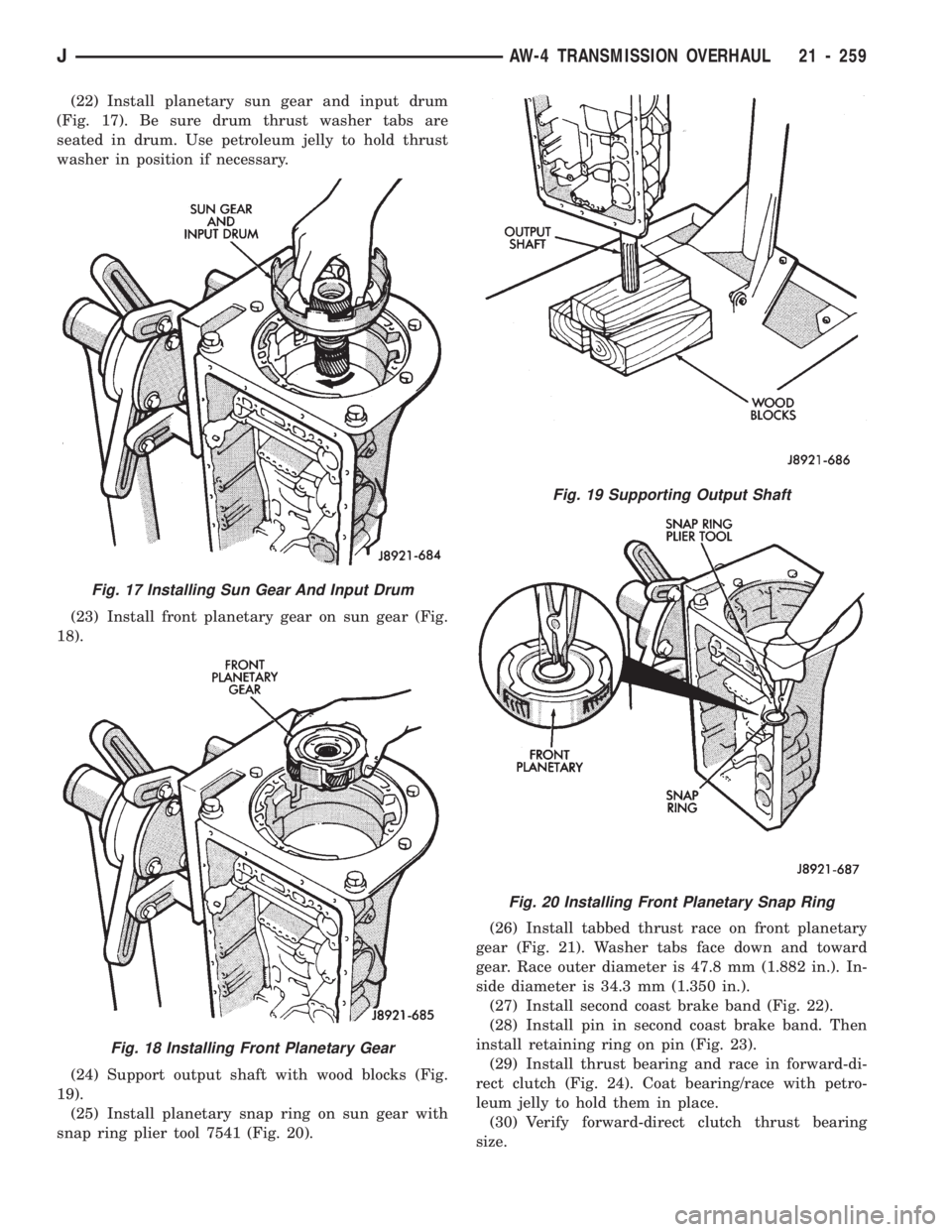
(22) Install planetary sun gear and input drum
(Fig. 17). Be sure drum thrust washer tabs are
seated in drum. Use petroleum jelly to hold thrust
washer in position if necessary.
(23) Install front planetary gear on sun gear (Fig.
18).
(24) Support output shaft with wood blocks (Fig.
19).
(25) Install planetary snap ring on sun gear with
snap ring plier tool 7541 (Fig. 20).(26) Install tabbed thrust race on front planetary
gear (Fig. 21). Washer tabs face down and toward
gear. Race outer diameter is 47.8 mm (1.882 in.). In-
side diameter is 34.3 mm (1.350 in.).
(27) Install second coast brake band (Fig. 22).
(28) Install pin in second coast brake band. Then
install retaining ring on pin (Fig. 23).
(29) Install thrust bearing and race in forward-di-
rect clutch (Fig. 24). Coat bearing/race with petro-
leum jelly to hold them in place.
(30) Verify forward-direct clutch thrust bearing
size.
Fig. 17 Installing Sun Gear And Input Drum
Fig. 18 Installing Front Planetary Gear
Fig. 19 Supporting Output Shaft
Fig. 20 Installing Front Planetary Snap Ring
JAW-4 TRANSMISSION OVERHAUL 21 - 259
Page 1373 of 1784
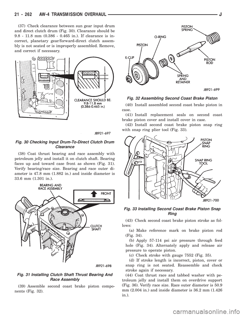
(37) Check clearance between sun gear input drum
and direct clutch drum (Fig. 30). Clearance should be
9.8 - 11.8 mm (0.386 - 0.465 in.). If clearance is in-
correct, planetary gear/forward-direct clutch assem-
bly is not seated or is improperly assembled. Remove,
and correct if necessary.
(38) Coat thrust bearing and race assembly with
petroleum jelly and install it on clutch shaft. Bearing
faces up and toward case front as shown (Fig. 31).
Verify bearing/race size. Bearing and race outer di-
ameter is 47.8 mm (1.882 in.) and inside diameter is
33.6 mm (1.301 in.).
(39) Assemble second coast brake piston compo-
nents (Fig. 32).(40) Install assembled second coast brake piston in
case.
(41) Install replacement seals on second coast
brake piston cover and install cover in case.
(42) Install second coast brake piston snap ring
with snap ring plier tool (Fig. 33).
(43) Check second coast brake piston stroke as fol-
lows:
(a) Make reference mark on brake piston rod
(Fig. 34).
(b) Apply 57-114 psi air pressure through feed
hole (Fig. 34). Alternately apply and release air
pressure to operate piston.
(c) Check stroke with gauge 7552 (Fig. 35).
(d) If stroke length is incorrect, piston, cover or
snap ring is not seated. Reassemble and check
stroke again if necessary.
(44) Coat thrust race and tabbed washer with pe-
troleum jelly and install them on overdrive support
(Fig. 36). Verify race size. Race outer diameter is 50.9
mm (2.004 in.) and inside diameter is 36.2 mm (1.426
in.).
Fig. 30 Checking Input Drum-To-Direct Clutch Drum
Clearance
Fig. 31 Installing Clutch Shaft Thrust Bearing And
Race Assembly
Fig. 32 Assembling Second Coast Brake Piston
Fig. 33 Installing Second Coast Brake Piston Snap
Ring
21 - 262 AW-4 TRANSMISSION OVERHAULJ