1994 JEEP CHEROKEE tow
[x] Cancel search: towPage 1103 of 1784
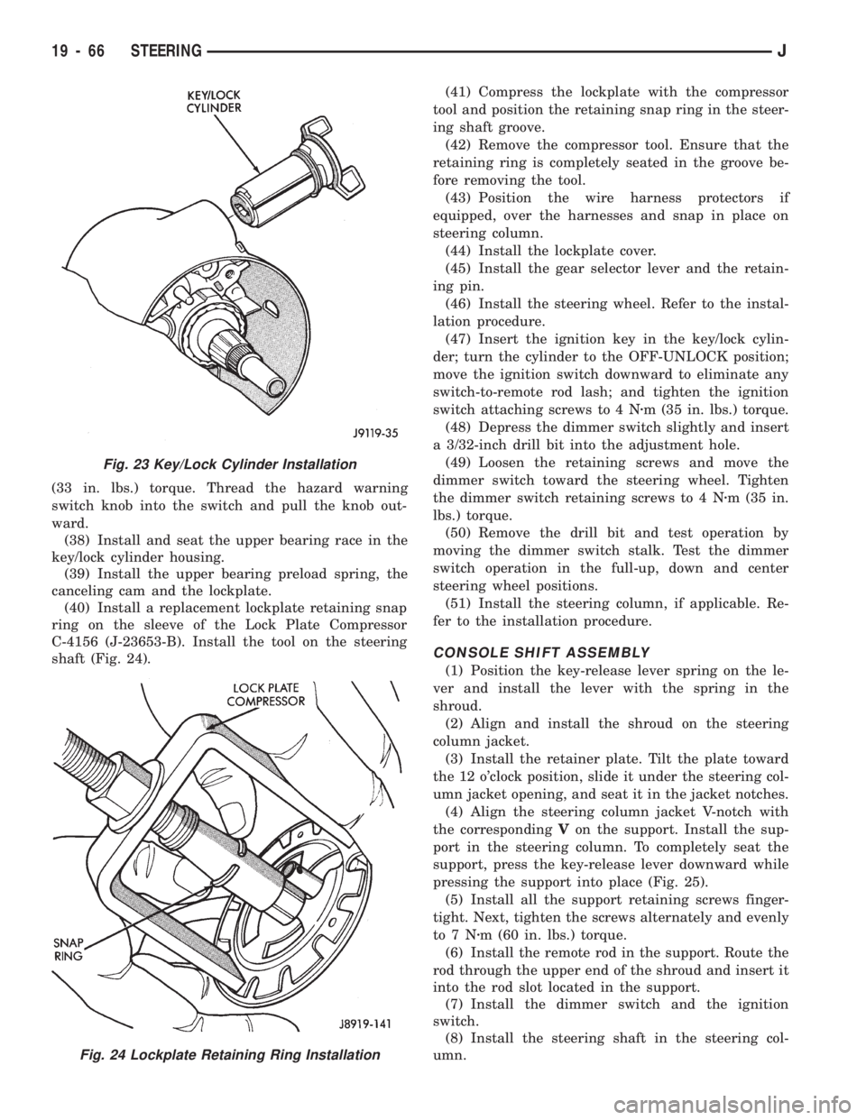
(33 in. lbs.) torque. Thread the hazard warning
switch knob into the switch and pull the knob out-
ward.
(38) Install and seat the upper bearing race in the
key/lock cylinder housing.
(39) Install the upper bearing preload spring, the
canceling cam and the lockplate.
(40) Install a replacement lockplate retaining snap
ring on the sleeve of the Lock Plate Compressor
C-4156 (J-23653-B). Install the tool on the steering
shaft (Fig. 24).(41) Compress the lockplate with the compressor
tool and position the retaining snap ring in the steer-
ing shaft groove.
(42) Remove the compressor tool. Ensure that the
retaining ring is completely seated in the groove be-
fore removing the tool.
(43) Position the wire harness protectors if
equipped, over the harnesses and snap in place on
steering column.
(44) Install the lockplate cover.
(45) Install the gear selector lever and the retain-
ing pin.
(46) Install the steering wheel. Refer to the instal-
lation procedure.
(47) Insert the ignition key in the key/lock cylin-
der; turn the cylinder to the OFF-UNLOCK position;
move the ignition switch downward to eliminate any
switch-to-remote rod lash; and tighten the ignition
switch attaching screws to 4 Nzm (35 in. lbs.) torque.
(48) Depress the dimmer switch slightly and insert
a 3/32-inch drill bit into the adjustment hole.
(49) Loosen the retaining screws and move the
dimmer switch toward the steering wheel. Tighten
the dimmer switch retaining screws to 4 Nzm (35 in.
lbs.) torque.
(50) Remove the drill bit and test operation by
moving the dimmer switch stalk. Test the dimmer
switch operation in the full-up, down and center
steering wheel positions.
(51) Install the steering column, if applicable. Re-
fer to the installation procedure.
CONSOLE SHIFT ASSEMBLY
(1) Position the key-release lever spring on the le-
ver and install the lever with the spring in the
shroud.
(2) Align and install the shroud on the steering
column jacket.
(3) Install the retainer plate. Tilt the plate toward
the 12 o'clock position, slide it under the steering col-
umn jacket opening, and seat it in the jacket notches.
(4) Align the steering column jacket V-notch with
the correspondingVon the support. Install the sup-
port in the steering column. To completely seat the
support, press the key-release lever downward while
pressing the support into place (Fig. 25).
(5) Install all the support retaining screws finger-
tight. Next, tighten the screws alternately and evenly
to7Nzm (60 in. lbs.) torque.
(6) Install the remote rod in the support. Route the
rod through the upper end of the shroud and insert it
into the rod slot located in the support.
(7) Install the dimmer switch and the ignition
switch.
(8) Install the steering shaft in the steering col-
umn.
Fig. 23 Key/Lock Cylinder Installation
Fig. 24 Lockplate Retaining Ring Installation
19 - 66 STEERINGJ
Page 1105 of 1784
(25) Install the windshield wiper wire harness and
switch. Route the wire harness down through steer-
ing column jacket.
(26) If equipped, install the cruise control wire har-
ness. Install the turn signal stalk by pushing it
straight into the column.
(27) Insert the hazard warning knob in the hazard
warning switch and press it inward. Align and install
the turn signal switch retaining screws. Ensure that
the turn signal switch is properly seated before tight-
ening the screws. Tighten the screws to 4 Nzm (33 in.
lbs.) torque. Thread the hazard warning switch knob
into the switch and pull the knob outward.
(28) Install and seat the upper bearing race in the
key/lock cylinder housing.
(29) Install the upper bearing preload spring, the
canceling cam and the lockplate.
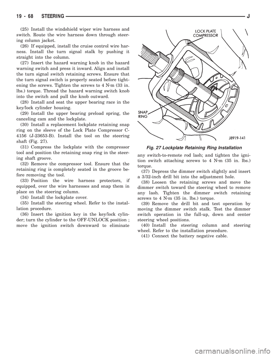
(30) Install a replacement lockplate retaining snap
ring on the sleeve of the Lock Plate Compressor C-
4156 (J-23653-B). Install the tool on the steering
shaft (Fig. 27).
(31) Compress the lockplate with the compressor
tool and position the retaining snap ring in the steer-
ing shaft groove.
(32) Remove the compressor tool. Ensure that the
retaining ring is completely seated in the groove be-
fore removing the tool.
(33) Position the wire harness protectors, if
equipped, over the wire harnesses and snap them in
place on the steering column.
(34) Install the lockplate cover.
(35) Install the steering wheel. Refer to the instal-
lation procedure.
(36) Insert the ignition key in the key/lock cylin-
der; turn the cylinder to the OFF-UNLOCK position ;
move the ignition switch downward to eliminateany switch-to-remote rod lash; and tighten the igni-
tion switch attaching screws to 4 Nzm (35 in. lbs.)
torque.
(37) Depress the dimmer switch slightly and insert
a 3/32-inch drill bit into the adjustment hole.
(38) Loosen the retaining screws and move the
dimmer switch toward the steering wheel to remove
any lash. Tighten the dimmer switch retaining
screws to 4 Nzm (35 in. lbs.) torque.
(39) Remove the drill bit and test operation by
moving the dimmer switch stalk. Test the dimmer
switch operation in the full-up, down and center
steering wheel positions.
(40) Install the steering column and steering
wheel. Refer to the installation procedure.
(41) Connect the battery negative cable.
Fig. 27 Lockplate Retaining Ring Installation
19 - 68 STEERINGJ
Page 1112 of 1784
TRANSMISSION AND TRANSFER CASE
CONTENTS
page page
30RH/32RH AUTOMATIC TRANSMISSION . . . 66
AW-4 AUTOMATIC TRANSMISSION........ 156AX 15 MANUAL TRANSMISSION.......... 32
AX 4/5 MANUAL TRANSMISSION........... 1
AX 4/5 MANUAL TRANSMISSION
INDEX
page page
Cleaning and Inspection................... 13
Gear Ratios............................. 2
General Information........................ 1
Recommended Lubricant.................... 2
Service Diagnosis......................... 2
Shift Pattern............................. 2Transmission Assembly and Adjustment....... 15
Transmission Disassembly and Overhaul........ 5
Transmission Identification................... 1
Transmission Installation.................... 4
Transmission Removal..................... 3
GENERAL INFORMATION
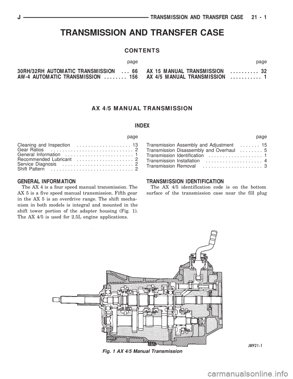
The AX 4 is a four speed manual transmission. The
AX 5 is a five speed manual transmission. Fifth gear
in the AX 5 is an overdrive range. The shift mecha-
nism in both models is integral and mounted in the
shift tower portion of the adapter housing (Fig. 1).
The AX 4/5 is used for 2.5L engine applications.
TRANSMISSION IDENTIFICATION
The AX 4/5 identification code is on the bottom
surface of the transmission case near the fill plug
Fig. 1 AX 4/5 Manual Transmission
JTRANSMISSION AND TRANSFER CASE 21 - 1
Page 1115 of 1784
(6) Remove slave cylinder from clutch housing.
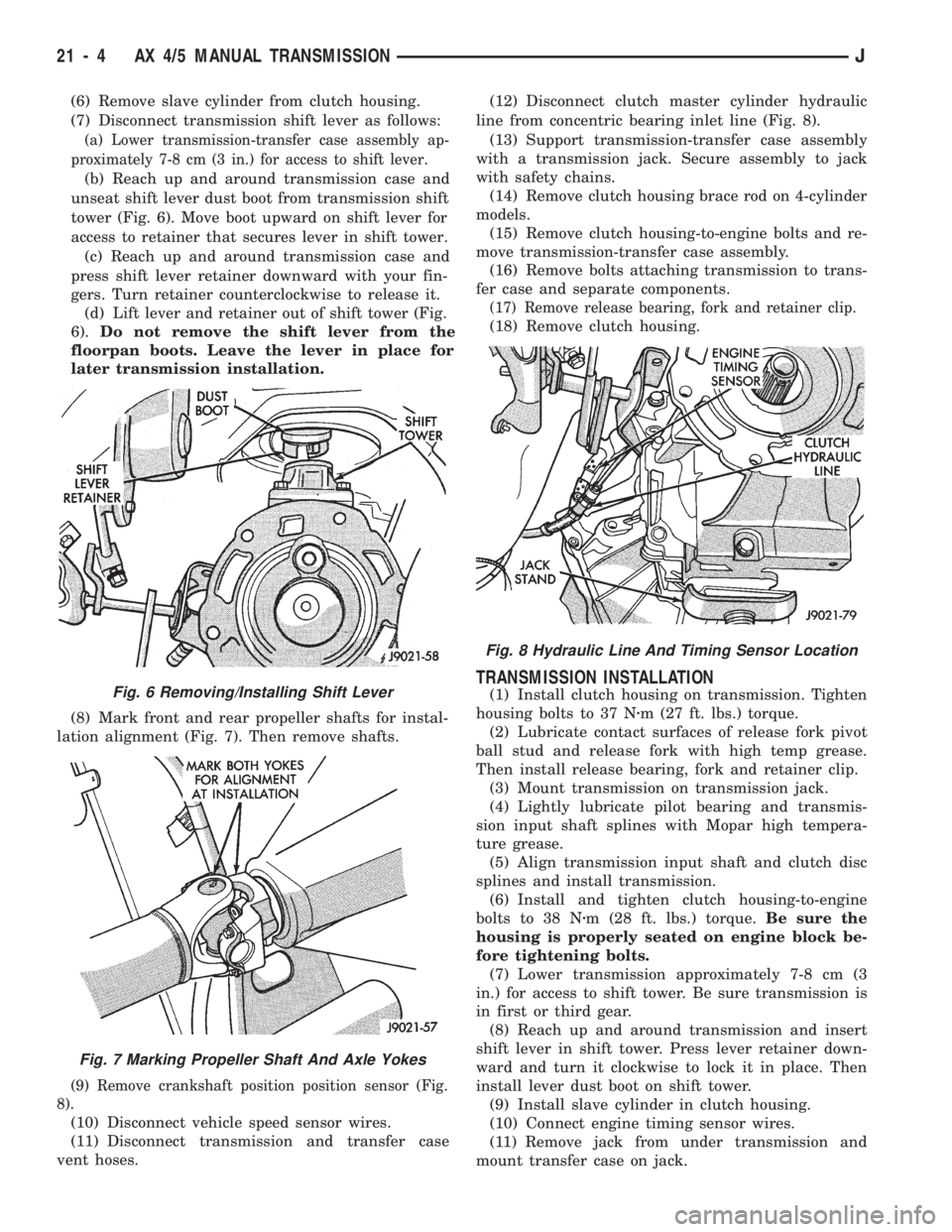
(7) Disconnect transmission shift lever as follows:
(a) Lower transmission-transfer case assembly ap-
proximately 7-8 cm (3 in.) for access to shift lever.
(b) Reach up and around transmission case and
unseat shift lever dust boot from transmission shift
tower (Fig. 6). Move boot upward on shift lever for
access to retainer that secures lever in shift tower.
(c) Reach up and around transmission case and
press shift lever retainer downward with your fin-
gers. Turn retainer counterclockwise to release it.
(d) Lift lever and retainer out of shift tower (Fig.
6).Do not remove the shift lever from the
floorpan boots. Leave the lever in place for
later transmission installation.
(8) Mark front and rear propeller shafts for instal-
lation alignment (Fig. 7). Then remove shafts.
(9) Remove crankshaft position position sensor (Fig.
8).
(10) Disconnect vehicle speed sensor wires.
(11) Disconnect transmission and transfer case
vent hoses.(12) Disconnect clutch master cylinder hydraulic
line from concentric bearing inlet line (Fig. 8).
(13) Support transmission-transfer case assembly
with a transmission jack. Secure assembly to jack
with safety chains.
(14) Remove clutch housing brace rod on 4-cylinder
models.
(15) Remove clutch housing-to-engine bolts and re-
move transmission-transfer case assembly.
(16) Remove bolts attaching transmission to trans-
fer case and separate components.
(17) Remove release bearing, fork and retainer clip.
(18) Remove clutch housing.
TRANSMISSION INSTALLATION
(1) Install clutch housing on transmission. Tighten
housing bolts to 37 Nzm (27 ft. lbs.) torque.
(2) Lubricate contact surfaces of release fork pivot
ball stud and release fork with high temp grease.
Then install release bearing, fork and retainer clip.
(3) Mount transmission on transmission jack.
(4) Lightly lubricate pilot bearing and transmis-
sion input shaft splines with Mopar high tempera-
ture grease.
(5) Align transmission input shaft and clutch disc
splines and install transmission.
(6) Install and tighten clutch housing-to-engine
bolts to 38 Nzm (28 ft. lbs.) torque.Be sure the
housing is properly seated on engine block be-
fore tightening bolts.
(7) Lower transmission approximately 7-8 cm (3
in.) for access to shift tower. Be sure transmission is
in first or third gear.
(8) Reach up and around transmission and insert
shift lever in shift tower. Press lever retainer down-
ward and turn it clockwise to lock it in place. Then
install lever dust boot on shift tower.
(9) Install slave cylinder in clutch housing.
(10) Connect engine timing sensor wires.
(11) Remove jack from under transmission and
mount transfer case on jack.Fig. 6 Removing/Installing Shift Lever
Fig. 7 Marking Propeller Shaft And Axle Yokes
Fig. 8 Hydraulic Line And Timing Sensor Location
21 - 4 AX 4/5 MANUAL TRANSMISSIONJ
Page 1124 of 1784
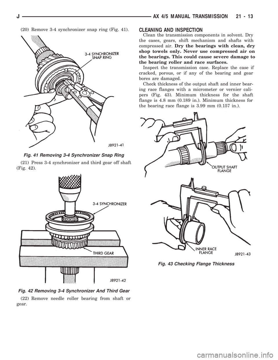
(20) Remove 3-4 synchronizer snap ring (Fig. 41).
(21) Press 3-4 synchronizer and third gear off shaft
(Fig. 42).
(22) Remove needle roller bearing from shaft or
gear.CLEANING AND INSPECTION
Clean the transmission components in solvent. Dry
the cases, gears, shift mechanism and shafts with
compressed air.Dry the bearings with clean, dry
shop towels only. Never use compressed air on
the bearings. This could cause severe damage to
the bearing roller and race surfaces.
Inspect the transmission case. Replace the case if
cracked, porous, or if any of the bearing and gear
bores are damaged.
Check thickness of the output shaft and inner bear-
ing race flanges with a micrometer or vernier cali-
pers (Fig. 43). Minimum thickness for the shaft
flange is 4.8 mm (0.189 in.). Minimum thickness for
the bearing race flange is 3.99 mm (0.157 in.).
Fig. 41 Removing 3-4 Synchronizer Snap Ring
Fig. 42 Removing 3-4 Synchronizer And Third Gear
Fig. 43 Checking Flange Thickness
JAX 4/5 MANUAL TRANSMISSION 21 - 13
Page 1129 of 1784
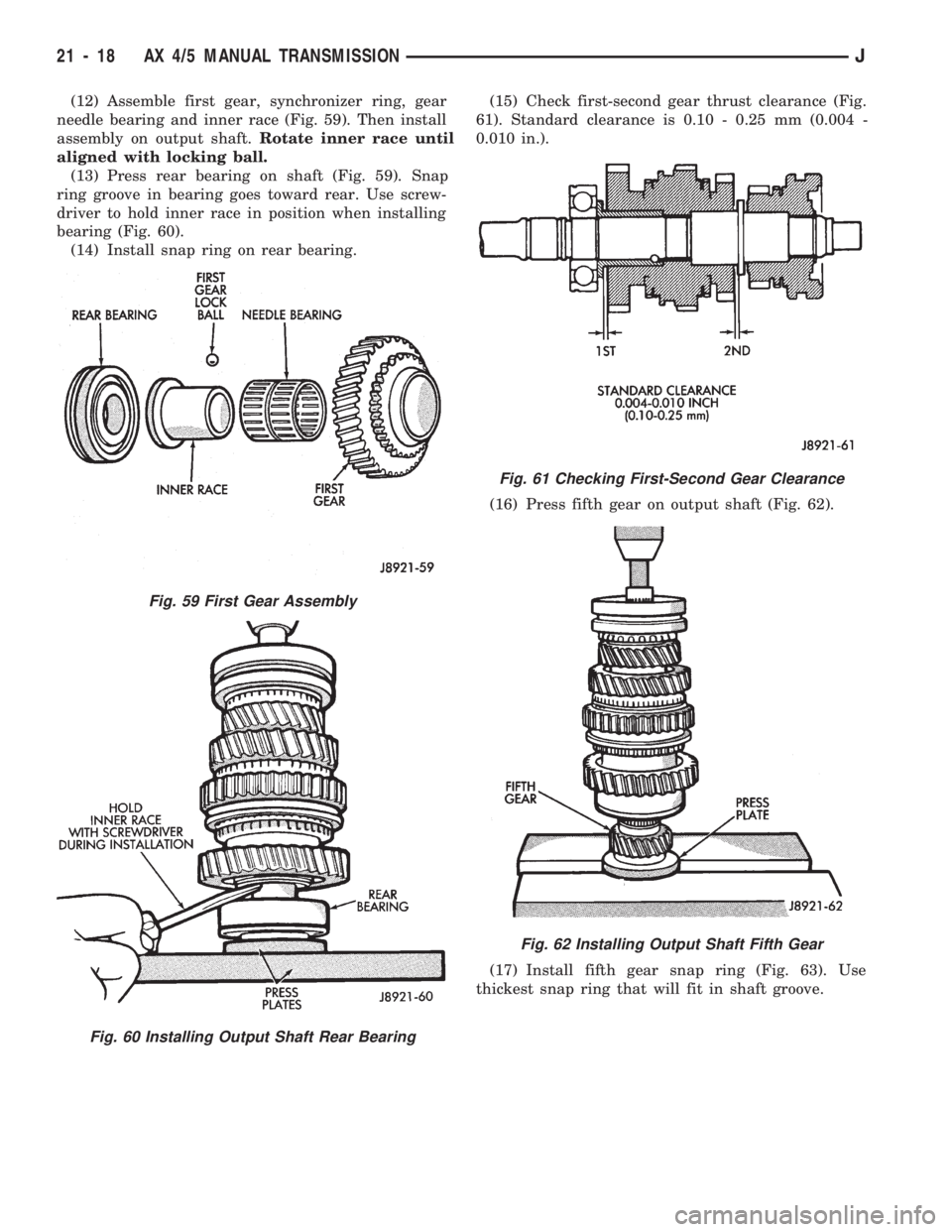
(12) Assemble first gear, synchronizer ring, gear
needle bearing and inner race (Fig. 59). Then install
assembly on output shaft.Rotate inner race until
aligned with locking ball.
(13) Press rear bearing on shaft (Fig. 59). Snap
ring groove in bearing goes toward rear. Use screw-
driver to hold inner race in position when installing
bearing (Fig. 60).
(14) Install snap ring on rear bearing.(15) Check first-second gear thrust clearance (Fig.
61). Standard clearance is 0.10 - 0.25 mm (0.004 -
0.010 in.).
(16) Press fifth gear on output shaft (Fig. 62).
(17) Install fifth gear snap ring (Fig. 63). Use
thickest snap ring that will fit in shaft groove.
Fig. 59 First Gear Assembly
Fig. 60 Installing Output Shaft Rear Bearing
Fig. 61 Checking First-Second Gear Clearance
Fig. 62 Installing Output Shaft Fifth Gear
21 - 18 AX 4/5 MANUAL TRANSMISSIONJ
Page 1141 of 1784
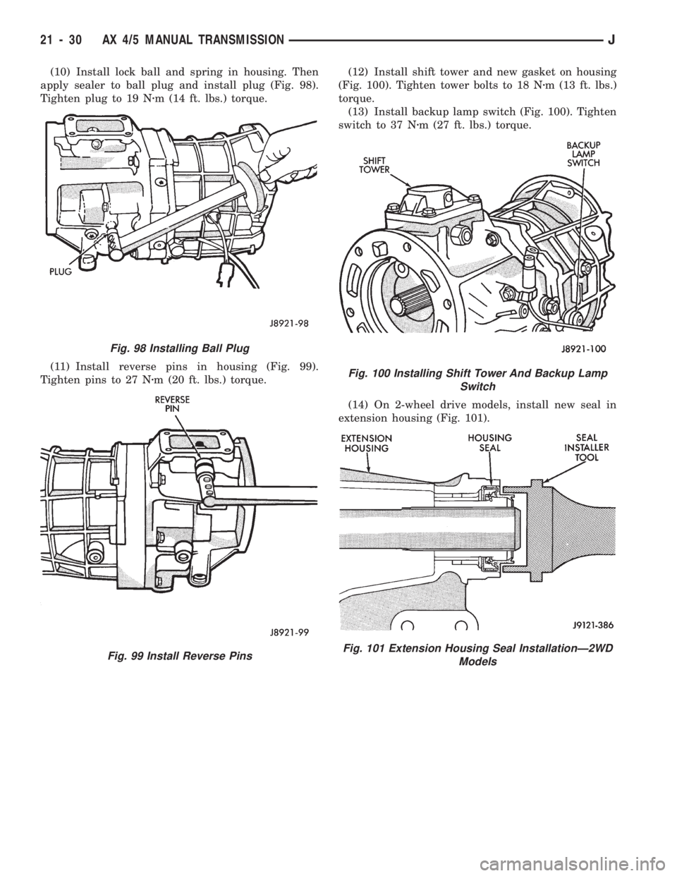
(10) Install lock ball and spring in housing. Then
apply sealer to ball plug and install plug (Fig. 98).
Tighten plug to 19 Nzm (14 ft. lbs.) torque.
(11) Install reverse pins in housing (Fig. 99).
Tighten pins to 27 Nzm (20 ft. lbs.) torque.(12) Install shift tower and new gasket on housing
(Fig. 100). Tighten tower bolts to 18 Nzm (13 ft. lbs.)
torque.
(13) Install backup lamp switch (Fig. 100). Tighten
switch to 37 Nzm (27 ft. lbs.) torque.
(14) On 2-wheel drive models, install new seal in
extension housing (Fig. 101).
Fig. 98 Installing Ball Plug
Fig. 99 Install Reverse Pins
Fig. 100 Installing Shift Tower And Backup Lamp
Switch
Fig. 101 Extension Housing Seal InstallationÐ2WD
Models
21 - 30 AX 4/5 MANUAL TRANSMISSIONJ
Page 1143 of 1784
AX 15 MANUAL TRANSMISSION
INDEX
page page
General Information....................... 32
Service Diagnosis........................ 33
Transmission Assembly and Adjustment....... 51
Transmission Disassembly and Overhaul....... 36
Transmission Gear Ratios.................. 33
Transmission Identification.................. 32Transmission InstallationÐAX 15............. 35
Transmission Lubricant.................... 33
Transmission RemovalÐAX 15.............. 34
Transmission Shift Pattern.................. 33
Transmission Switch and Plug Locations....... 33
GENERAL INFORMATION
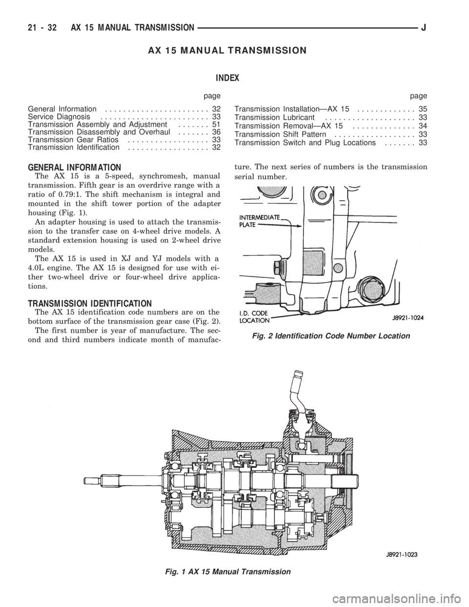
The AX 15 is a 5-speed, synchromesh, manual
transmission. Fifth gear is an overdrive range with a
ratio of 0.79:1. The shift mechanism is integral and
mounted in the shift tower portion of the adapter
housing (Fig. 1).
An adapter housing is used to attach the transmis-
sion to the transfer case on 4-wheel drive models. A
standard extension housing is used on 2-wheel drive
models.
The AX 15 is used in XJ and YJ models with a
4.0L engine. The AX 15 is designed for use with ei-
ther two-wheel drive or four-wheel drive applica-
tions.
TRANSMISSION IDENTIFICATION
The AX 15 identification code numbers are on the
bottom surface of the transmission gear case (Fig. 2).
The first number is year of manufacture. The sec-
ond and third numbers indicate month of manufac-ture. The next series of numbers is the transmission
serial number.
Fig. 1 AX 15 Manual Transmission
Fig. 2 Identification Code Number Location
21 - 32 AX 15 MANUAL TRANSMISSIONJ