1994 JEEP CHEROKEE tow
[x] Cancel search: towPage 1374 of 1784
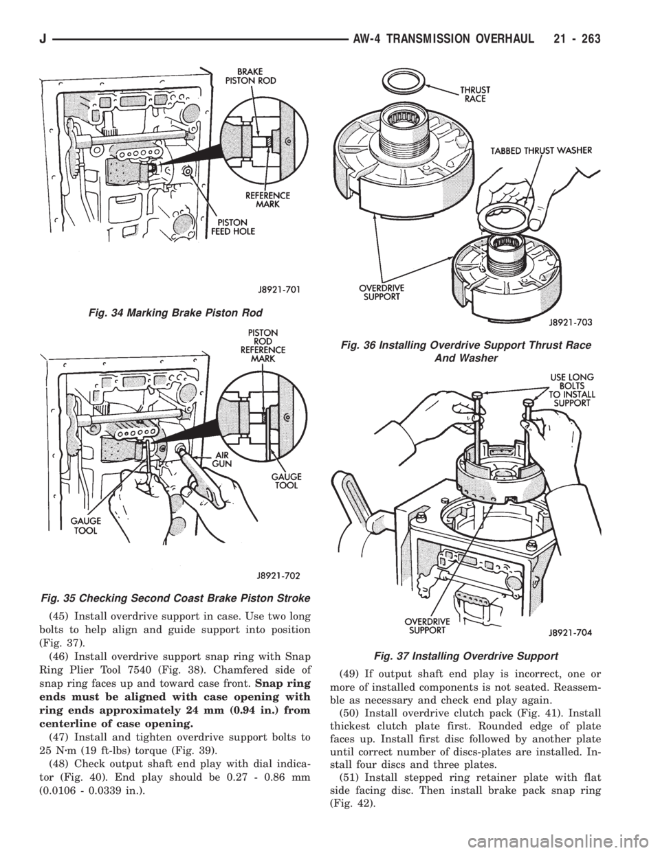
(45) Install overdrive support in case. Use two long
bolts to help align and guide support into position
(Fig. 37).
(46) Install overdrive support snap ring with Snap
Ring Plier Tool 7540 (Fig. 38). Chamfered side of
snap ring faces up and toward case front.Snap ring
ends must be aligned with case opening with
ring ends approximately 24 mm (0.94 in.) from
centerline of case opening.
(47) Install and tighten overdrive support bolts to
25 Nzm (19 ft-lbs) torque (Fig. 39).
(48) Check output shaft end play with dial indica-
tor (Fig. 40). End play should be 0.27 - 0.86 mm
(0.0106 - 0.0339 in.).(49) If output shaft end play is incorrect, one or
more of installed components is not seated. Reassem-
ble as necessary and check end play again.
(50) Install overdrive clutch pack (Fig. 41). Install
thickest clutch plate first. Rounded edge of plate
faces up. Install first disc followed by another plate
until correct number of discs-plates are installed. In-
stall four discs and three plates.
(51) Install stepped ring retainer plate with flat
side facing disc. Then install brake pack snap ring
(Fig. 42).
Fig. 36 Installing Overdrive Support Thrust Race
And Washer
Fig. 37 Installing Overdrive Support
Fig. 34 Marking Brake Piston Rod
Fig. 35 Checking Second Coast Brake Piston Stroke
JAW-4 TRANSMISSION OVERHAUL 21 - 263
Page 1477 of 1784
(2) Carefully pry the applique off the license plate
visor and tailgate (Fig. 62).
INSTALLATION
(1) Align the moulding with the visor and then
press the applique into place.
(2) Install the rivets to attach the outboard tabs on
applique to the tailgate.
WOODGRAIN OVERLAY
SERVICE INFORMATION
Exterior woodgrain overlay is a weather-resistant
vinyl. The adhesive backing is protected by a paper
liner until removed for installation.
OVERLAY REPAIR
Small nicks and scratches on an overlay can be
touched-up with paint.
To eliminate blisters and air bubbles, pierce them
with a needle or pin. Force the trapped air out of the
hole and press firmly on the overlay. Heat also can
be applied to remove small wrinkles.
Whenever an overlay must be stretched, do
not slit or cut it. Instead, apply heat and press
or squeegee the overlay into place.
INSTALLATION REQUIREMENTS
Overlay replacement requires metal repair and
paint refinish to be completed before the overlay is
installed.
The work area temperature should be between
18ÉC (65ÉF) and 32ÉC (90ÉF).A woodgrain overlay
should not be replaced if the work area temper-
ature is less than 18ÉC (65ÉF).
The following equipment and material are neces-
sary for overlay installation:
²a commercial woodgrain overlay removal solution;
²a commercial adhesive removal solution;
²liquid dish detergent (for wetting solution);
²a mixture of wetting solution;
²a commercial wax and silicone removal solution;
²isopropyl alcohol (rubbing alcohol);
²a squeegee (4 to 5 inches wide, plastic or hard rub-
ber);
²a water bucket and sponge;
²sandpaper (no. 360 or no. 400, wet or dry type);
²a heat gun (or infra-red heat bulb);
²clean wiping rags or paper towels;
²a pair of scissors;
²a needle or pin; and
²a wax pencil.
Using a wetting solution helps the installation of
an overlay. Prepare a solution by mixing two or three
teaspoons of dish detergent with 1 gallon of water.
Do not use soap.
Too much detergent will reduce the effective-
ness of the mixture.
OVERLAY REMOVAL
(1) Remove the adjacent moulding from panel.
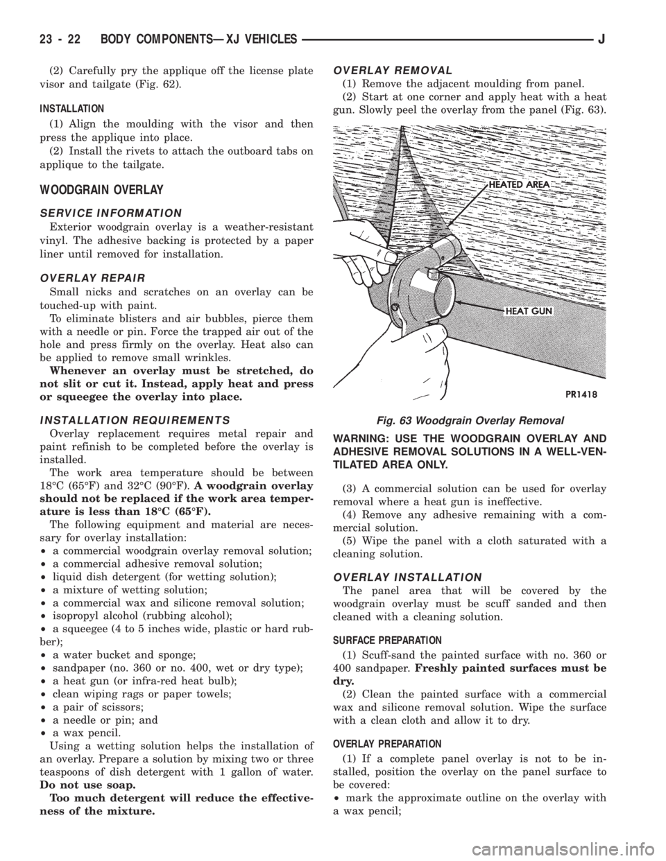
(2) Start at one corner and apply heat with a heat
gun. Slowly peel the overlay from the panel (Fig. 63).
WARNING: USE THE WOODGRAIN OVERLAY AND
ADHESIVE REMOVAL SOLUTIONS IN A WELL-VEN-
TILATED AREA ONLY.
(3) A commercial solution can be used for overlay
removal where a heat gun is ineffective.
(4) Remove any adhesive remaining with a com-
mercial solution.
(5) Wipe the panel with a cloth saturated with a
cleaning solution.
OVERLAY INSTALLATION
The panel area that will be covered by the
woodgrain overlay must be scuff sanded and then
cleaned with a cleaning solution.
SURFACE PREPARATION
(1) Scuff-sand the painted surface with no. 360 or
400 sandpaper.Freshly painted surfaces must be
dry.
(2) Clean the painted surface with a commercial
wax and silicone removal solution. Wipe the surface
with a clean cloth and allow it to dry.
OVERLAY PREPARATION
(1) If a complete panel overlay is not to be in-
stalled, position the overlay on the panel surface to
be covered:
²mark the approximate outline on the overlay with
a wax pencil;
Fig. 63 Woodgrain Overlay Removal
23 - 22 BODY COMPONENTSÐXJ VEHICLESJ
Page 1478 of 1784
²ensure that 12 mm (1/2 in) excess overlay material
is allowed for wrapping around the door and fender
flanges; and
²cut the overlay to the approximate size with scis-
sors.
(2) Place the overlay on a clean, flat surface with
the paper liner facing upward.
(3) Bend the corner of the overlay toward the
woodgrain side and, with a flick of the finger, sepa-
rate the paper liner from the overlay.
OVERLAY APPLICATION
(1) Use a clean sponge and apply the wetting solu-
tion to the overlay adhesive and to the painted panel
surface.
(2) Position the adhesive side of the overlay on the
panel.
(3) Apply solution to the woodgrain side of the
overlay.
(4) For a complete, or a large section of overlay,
the following method should be used:
²position a squeegee at the center and slide it
across a short horizontal area of overlay;
²lift the right or left edge of the overlay, align it
with the panel. Slide the squeegee toward the lifted
edge with firm strokes;
²avoid stretching the overlay at its lifted edge;
²continue until all of the air bubbles and wetting
solution are removed from the underside of the over-
lay.
If a wrinkle is trapped in the overlay, stop im-
mediately. Lift the wrinkled area and re-align it
to remove the wrinkle. Do not lift the overlay if
only a few air bubbles exist.
(5) Notch the corner and curved edges of the over-
lay and trim the excess.
(6) Allow 12 mm (1/2 in) extra overlay to extend
beyond the edges.CAUTION: Use extreme care to avoid spilling iso-
propyl (rubbing) alcohol on the moulding or painted
surfaces. Wipe spills immediately.
(7) Wipe the adhesive side of edges with isopropyl
alcohol.
(8) Heat the overlay edges with a heat gun to
soften and make them more pliable.
(9) Fold the edges over onto the panel flange area
and press the overlay into place. Alternately heat
and press the edge until it is bonded to the flange
area.
(10) Carefully cut away the excess from panel the
openings with a knife.
(11) Inspect the overlay. Remove all the air and
moisture bubbles with a needle or pin.
(12) Install all the removed components and clean
the vehicle as necessary.
FRONT FENDER OVERLAY APPLICATION
Install a complete front fender overlay according to
the following instructions.
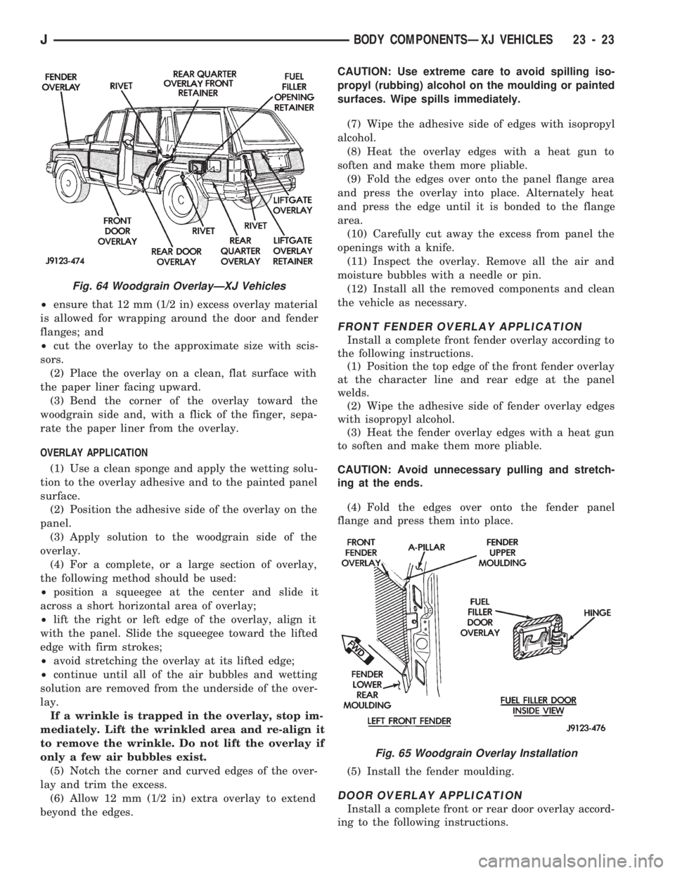
(1) Position the top edge of the front fender overlay
at the character line and rear edge at the panel
welds.
(2) Wipe the adhesive side of fender overlay edges
with isopropyl alcohol.
(3) Heat the fender overlay edges with a heat gun
to soften and make them more pliable.
CAUTION: Avoid unnecessary pulling and stretch-
ing at the ends.
(4) Fold the edges over onto the fender panel
flange and press them into place.
(5) Install the fender moulding.
DOOR OVERLAY APPLICATION
Install a complete front or rear door overlay accord-
ing to the following instructions.
Fig. 64 Woodgrain OverlayÐXJ Vehicles
Fig. 65 Woodgrain Overlay Installation
JBODY COMPONENTSÐXJ VEHICLES 23 - 23
Page 1480 of 1784
FUEL FILLER DOOR OVERLAY APPLICATION
(1) Clean the door flange with an appropriate solu-
tion.
(2) Position the top edge of the overlay at the char-
acter line and notches at door edge.
(3) Wipe the adhesive side of fuel filler door over-
lay edges with isopropyl alcohol.
(4) Heat the door overlay edges with a heat gun to
soften and make them more pliable.
CAUTION: Avoid unnecessary pulling and stretch-
ing at the ends.
(5) Fold the overlay edges over onto the door panel
flange areas and press them into place.
LIFTGATE OVERLAY APPLICATION
(1) Position the top edge of the overlay at charac-
ter line and inner edges at the license plate recess.
(2) Wipe the adhesive side of the liftgate overlay
edges with isopropyl alcohol.
(3) Heat the liftgate overlay edges with a heat gun
to soften and make them more pliable.
CAUTION: Avoid unnecessary pulling and stretch-
ing at the ends.
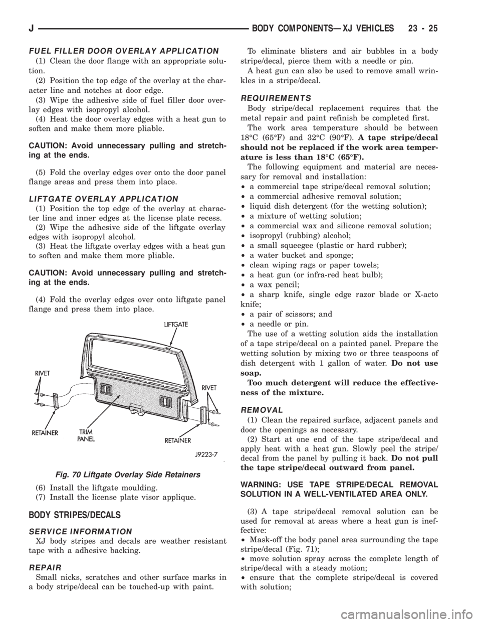
(4) Fold the overlay edges over onto liftgate panel
flange and press them into place.
(6) Install the liftgate moulding.
(7) Install the license plate visor applique.
BODY STRIPES/DECALS
SERVICE INFORMATION
XJ body stripes and decals are weather resistant
tape with a adhesive backing.
REPAIR
Small nicks, scratches and other surface marks in
a body stripe/decal can be touched-up with paint.To eliminate blisters and air bubbles in a body
stripe/decal, pierce them with a needle or pin.
A heat gun can also be used to remove small wrin-
kles in a stripe/decal.
REQUIREMENTS
Body stripe/decal replacement requires that the
metal repair and paint refinish be completed first.
The work area temperature should be between
18ÉC (65ÉF) and 32ÉC (90ÉF).A tape stripe/decal
should not be replaced if the work area temper-
ature is less than 18ÉC (65ÉF).
The following equipment and material are neces-
sary for removal and installation:
²a commercial tape stripe/decal removal solution;
²a commercial adhesive removal solution;
²liquid dish detergent (for the wetting solution);
²a mixture of wetting solution;
²a commercial wax and silicone removal solution;
²isopropyl (rubbing) alcohol;
²a small squeegee (plastic or hard rubber);
²a water bucket and sponge;
²clean wiping rags or paper towels;
²a heat gun (or infra-red heat bulb);
²a wax pencil;
²a sharp knife, single edge razor blade or X-acto
knife;
²a pair of scissors; and
²a needle or pin.
The use of a wetting solution aids the installation
of a tape stripe/decal on a painted panel. Prepare the
wetting solution by mixing two or three teaspoons of
dish detergent with 1 gallon of water.Do not use
soap.
Too much detergent will reduce the effective-
ness of the mixture.
REMOVAL
(1) Clean the repaired surface, adjacent panels and
door the openings as necessary.
(2) Start at one end of the tape stripe/decal and
apply heat with a heat gun. Slowly peel the stripe/
decal from the panel by pulling it back.Do not pull
the tape stripe/decal outward from panel.
WARNING: USE TAPE STRIPE/DECAL REMOVAL
SOLUTION IN A WELL-VENTILATED AREA ONLY.
(3) A tape stripe/decal removal solution can be
used for removal at areas where a heat gun is inef-
fective:
²Mask-off the body panel area surrounding the tape
stripe/decal (Fig. 71);
²move solution spray across the complete length of
stripe/decal with a steady motion;
²ensure that the complete stripe/decal is covered
with solution;
Fig. 70 Liftgate Overlay Side Retainers
JBODY COMPONENTSÐXJ VEHICLES 23 - 25
Page 1525 of 1784
INSTALLATION
(1) Connect the replacement support rod and cylin-
der to the ball studs.
(2) Secure the support rod and cylinder to the ball
studs with the retainer clips.
(3) Remove the support from the liftgate and test
the operation of the support rod.
LIFTGATE SUPPORT ROD CYLINDER DISPOSAL
WARNING: SAFETY GOGGLES MUST BE WORN
DURING THE DISPOSAL PROCEDURE. THE HIGH
PRESSURE GAS CHARGE IN THE SUPPORT ROD
CYLINDERS WILL BE RELEASED DURING THE
PROCEDURE.
(1) Remove the support rod cylinder(s) from the
liftgate.
(2) Position the support rod cylinder horizontally
in a vise and clamp the cylinder securely.
(3) Wrap the cylinder with 4-5 layers of shop tow-
els.
(4) Measure 1 and 1/2 inches inward from the end
of the cylinder. Mark this location on the towels with
chalk. The cylinder will be punctured at this location
to release the gas charge.
(5) Use a punch and hammer to puncture cylinder.
Force the punch through towels and into the cylinder
with a hammer. Continue striking the punch until
the gas begins to escapebut do not remove the
punch.
(6) Hold the towels and punch in position until all
the gas has escaped. Complete de-pressurization will
require about 4 to 10 seconds. After all the gas has
escaped, slowly remove the punch.
(7) Hold a towel over the hole in cylinder and press
the support rod piston all the way into the cylinder
to purge remaining oil.
(8) Remove the support rod cylinder from the vise
and discard it.
(9) If both support rod cylinders are being re-
placed, repeat this procedure for the remaining cylin-
der.
LIFTGATE SUPPORT ROD BALL STUD
REPLACEMENT
REMOVAL
(1) Open the liftgate.
(2) Support the liftgate in the open position.
(3) Remove the retainer clip that attaches the sup-
port rod and cylinder to the ball stud.
(4) Disconnect the support rod from the ball stud.
(5) Remove the ball stud from the liftgate with a
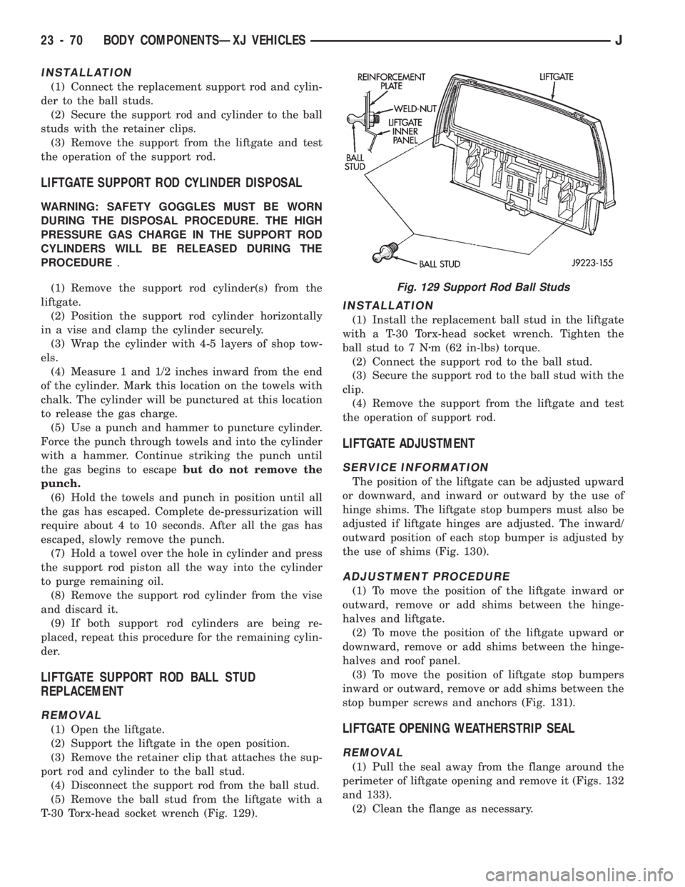
T-30 Torx-head socket wrench (Fig. 129).
INSTALLATION
(1) Install the replacement ball stud in the liftgate
with a T-30 Torx-head socket wrench. Tighten the
ball stud to 7 Nzm (62 in-lbs) torque.
(2) Connect the support rod to the ball stud.
(3) Secure the support rod to the ball stud with the
clip.
(4) Remove the support from the liftgate and test
the operation of support rod.
LIFTGATE ADJUSTMENT
SERVICE INFORMATION
The position of the liftgate can be adjusted upward
or downward, and inward or outward by the use of
hinge shims. The liftgate stop bumpers must also be
adjusted if liftgate hinges are adjusted. The inward/
outward position of each stop bumper is adjusted by
the use of shims (Fig. 130).
ADJUSTMENT PROCEDURE
(1) To move the position of the liftgate inward or
outward, remove or add shims between the hinge-
halves and liftgate.
(2) To move the position of the liftgate upward or
downward, remove or add shims between the hinge-
halves and roof panel.
(3) To move the position of liftgate stop bumpers
inward or outward, remove or add shims between the
stop bumper screws and anchors (Fig. 131).
LIFTGATE OPENING WEATHERSTRIP SEAL
REMOVAL
(1) Pull the seal away from the flange around the
perimeter of liftgate opening and remove it (Figs. 132
and 133).
(2) Clean the flange as necessary.
Fig. 129 Support Rod Ball Studs
23 - 70 BODY COMPONENTSÐXJ VEHICLESJ
Page 1530 of 1784
INTERIOR REARVIEW MIRROR SUPPORT
BRACKET REPLACEMENT
PREPARATION
(1) Mark reference lines for the mirror support
bracket on the outside of windshield glass with a wax
pencil.
(2) If the vinyl pad remained on the windshield
glass, soften and remove it with a heat gun.
(3) Clean the support bracket surface area on the
glass. Use a mild abrasive cleaning powder on a cloth
saturated with isopropyl (rubbing) alcohol.
(4) Lightly sand the contact surface on the support
bracket with fine grit sandpaper. Wipe bracket con-
tact surface clean with a paper towel and alcohol.
INSTALLATION
(1) Apply adhesive to the act surface on the sup-
port bracket according as follows:
²crush the vial in the plastic housing of the accel-
erator to saturate the felt applicator;
²remove the paper sleeve;
²apply a generous amount of accelerator to the con-
tact surface on the mirror support bracket;
²do not touch the support bracket contact surface
after the accelerator has been applied.
²allow the accelerator to dry for at least five min-
utes; and
(2) Apply accelerator to the support bracket con-
tact surface on the windshield glass. Allow the accel-
erator to dry for one minute.
(3) Install the mirror bracket on the windshield
glass follows:
²apply one drop of adhesive at the center of support
bracket contact surface on windshield glass;
²immediately apply an even coat of adhesive to the
contact surface on the support bracket;
²align the support bracket with the position refer-
ence lines on the windshield glass, then
²press and hold the support bracket in-place for at
least one minute.
Ensure that the mirror support bracket is
correctly aligned because the adhesive will
cure rapidly.
(4) Allow the adhesive to cure for 8-10 minutes,
then remove any residue adhesive with an alcohol-
dampened cloth.
(5) Allow the adhesive to cure for an additional
8-10 minutes before installing the mirror base on the
support bracket.
WINDSHIELD SERVICE INFORMATION
URETHANE ADHESIVE BONDING
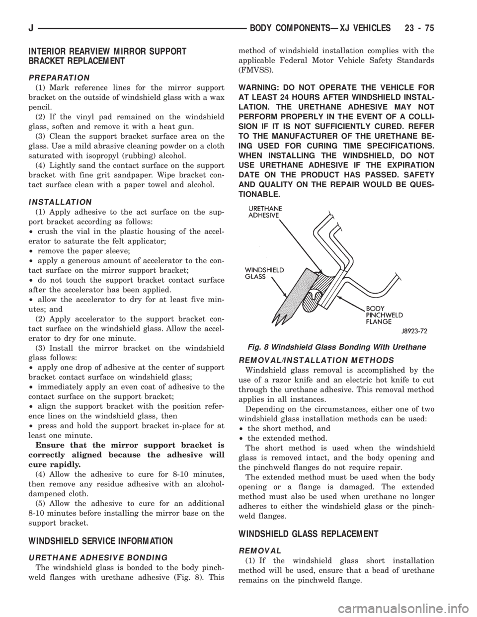
The windshield glass is bonded to the body pinch-
weld flanges with urethane adhesive (Fig. 8). Thismethod of windshield installation complies with the
applicable Federal Motor Vehicle Safety Standards
(FMVSS).
WARNING: DO NOT OPERATE THE VEHICLE FOR
AT LEAST 24 HOURS AFTER WINDSHIELD INSTAL-
LATION. THE URETHANE ADHESIVE MAY NOT
PERFORM PROPERLY IN THE EVENT OF A COLLI-
SION IF IT IS NOT SUFFICIENTLY CURED. REFER
TO THE MANUFACTURER OF THE URETHANE BE-
ING USED FOR CURING TIME SPECIFICATIONS.
WHEN INSTALLING THE WINDSHIELD, DO NOT
USE URETHANE ADHESIVE IF THE EXPIRATION
DATE ON THE PRODUCT HAS PASSED. SAFETY
AND QUALITY ON THE REPAIR WOULD BE QUES-
TIONABLE.
REMOVAL/INSTALLATION METHODS
Windshield glass removal is accomplished by the
use of a razor knife and an electric hot knife to cut
through the urethane adhesive. This removal method
applies in all instances.
Depending on the circumstances, either one of two
windshield glass installation methods can be used:
²the short method, and
²the extended method.
The short method is used when the windshield
glass is removed intact, and the body opening and
the pinchweld flanges do not require repair.
The extended method must be used when the body
opening or a flange is damaged. The extended
method must also be used when urethane no longer
adheres to either the windshield glass or the pinch-
weld flanges.
WINDSHIELD GLASS REPLACEMENT
REMOVAL
(1) If the windshield glass short installation
method will be used, ensure that a bead of urethane
remains on the pinchweld flange.
Fig. 8 Windshield Glass Bonding With Urethane
JBODY COMPONENTSÐXJ VEHICLES 23 - 75
Page 1536 of 1784
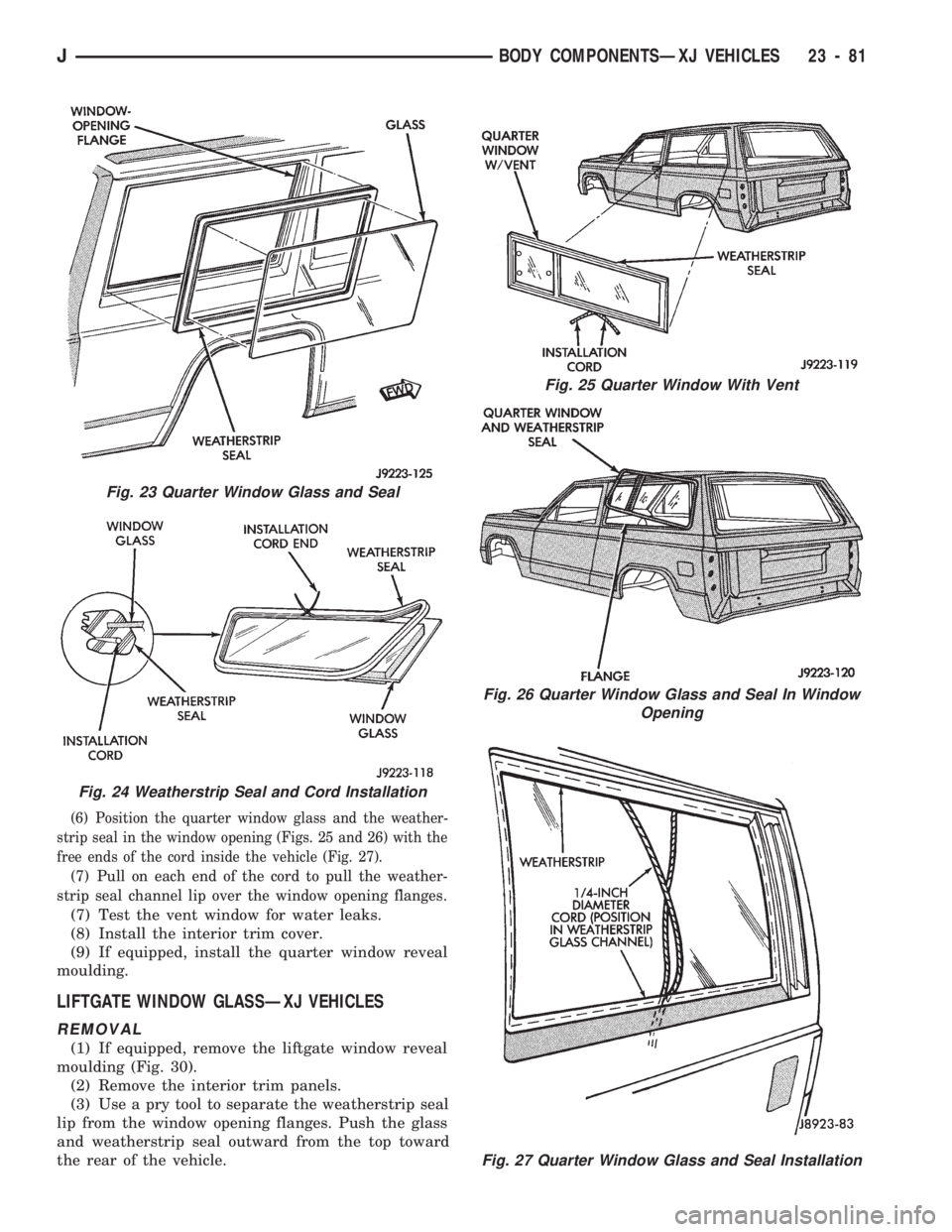
(6) Position the quarter window glass and the weather-
strip seal in the window opening (Figs. 25 and 26) with the
free ends of the cord inside the vehicle (Fig. 27).
(7) Pull on each end of the cord to pull the weather-
strip seal channel lip over the window opening flanges.
(7) Test the vent window for water leaks.
(8) Install the interior trim cover.
(9) If equipped, install the quarter window reveal
moulding.
LIFTGATE WINDOW GLASSÐXJ VEHICLES
REMOVAL
(1) If equipped, remove the liftgate window reveal
moulding (Fig. 30).
(2) Remove the interior trim panels.
(3) Use a pry tool to separate the weatherstrip seal
lip from the window opening flanges. Push the glass
and weatherstrip seal outward from the top toward
the rear of the vehicle.
Fig. 23 Quarter Window Glass and Seal
Fig. 25 Quarter Window With Vent
Fig. 26 Quarter Window Glass and Seal In Window
Opening
Fig. 27 Quarter Window Glass and Seal Installation
Fig. 24 Weatherstrip Seal and Cord Installation
JBODY COMPONENTSÐXJ VEHICLES 23 - 81
Page 1539 of 1784
UNDERBODY COMPONENTS
INDEX
page page
Catalytic Converter/Muffler/Tailpipe Support
Brackets............................. 85
Front Skid Plate......................... 84
Fuel and Brake Fluid Tube Retainer Clip....... 86
Fuel Filler Hose Splash ShieldÐXJ Vehicles.... 86
Fuel Filter Bracket........................ 86Fuel Tank Skid Plate...................... 84
Fuel Tank Support Strap................... 86
Rear Tow HookÐXJ Vehicles............... 87
Service Information....................... 84
Trailer Hitches........................... 88
Transfer Case Skid Plate.................. 84
SERVICE INFORMATION
In some cases, components in the following proce-
dures either support, or are concealed by other com-
ponents. When necessary, refer to component
removal procedure for service access.
FRONT SKID PLATE
REMOVAL
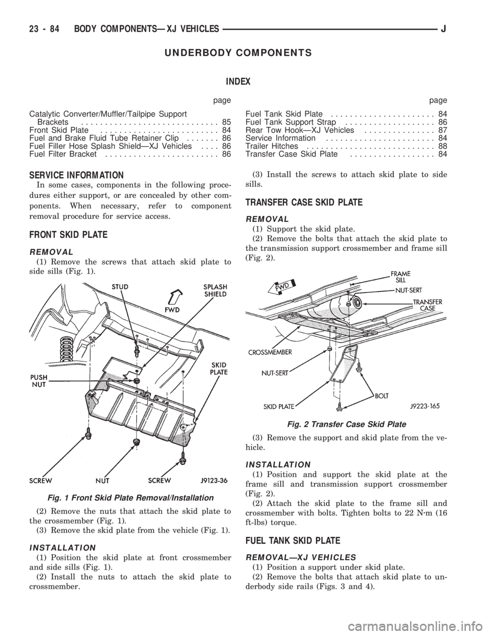
(1) Remove the screws that attach skid plate to
side sills (Fig. 1).
(2) Remove the nuts that attach the skid plate to
the crossmember (Fig. 1).
(3) Remove the skid plate from the vehicle (Fig. 1).
INSTALLATION
(1) Position the skid plate at front crossmember
and side sills (Fig. 1).
(2) Install the nuts to attach the skid plate to
crossmember.(3) Install the screws to attach skid plate to side
sills.
TRANSFER CASE SKID PLATE
REMOVAL
(1) Support the skid plate.
(2) Remove the bolts that attach the skid plate to
the transmission support crossmember and frame sill
(Fig. 2).
(3) Remove the support and skid plate from the ve-
hicle.
INSTALLATION
(1) Position and support the skid plate at the
frame sill and transmission support crossmember
(Fig. 2).
(2) Attach the skid plate to the frame sill and
crossmember with bolts. Tighten bolts to 22 Nzm (16
ft-lbs) torque.
FUEL TANK SKID PLATE
REMOVALÐXJ VEHICLES
(1) Position a support under skid plate.
(2) Remove the bolts that attach skid plate to un-
derbody side rails (Figs. 3 and 4).
Fig. 1 Front Skid Plate Removal/Installation
Fig. 2 Transfer Case Skid Plate
23 - 84 BODY COMPONENTSÐXJ VEHICLESJ