1994 JEEP CHEROKEE tow
[x] Cancel search: towPage 1630 of 1784
(6) Install the interior trim panel (Fig. 4).
(7) Connect the latch release rod to the door latch
interior release handle and install the handle (Fig.
4).
(8) Install the assist handle (Fig. 4).
(9) Install the window retaining sleeves (Fig. 2).
(10) Install the window (Fig. 1).
(11) Attach the restraint strap to the pin (Fig. 1).
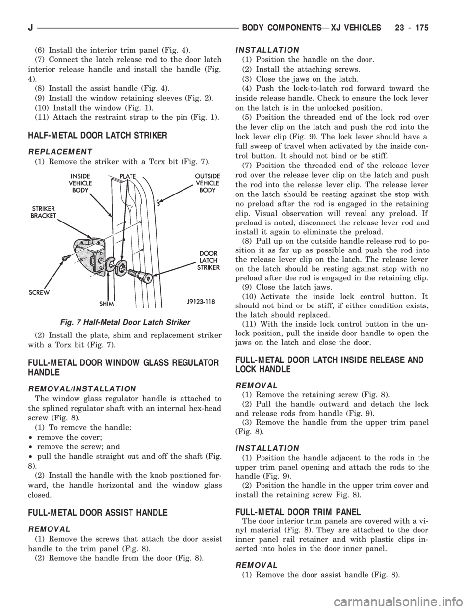
HALF-METAL DOOR LATCH STRIKER
REPLACEMENT
(1) Remove the striker with a Torx bit (Fig. 7).
(2) Install the plate, shim and replacement striker
with a Torx bit (Fig. 7).
FULL-METAL DOOR WINDOW GLASS REGULATOR
HANDLE
REMOVAL/INSTALLATION
The window glass regulator handle is attached to
the splined regulator shaft with an internal hex-head
screw (Fig. 8).
(1) To remove the handle:
²remove the cover;
²remove the screw; and
²pull the handle straight out and off the shaft (Fig.
8).
(2) Install the handle with the knob positioned for-
ward, the handle horizontal and the window glass
closed.
FULL-METAL DOOR ASSIST HANDLE
REMOVAL
(1) Remove the screws that attach the door assist
handle to the trim panel (Fig. 8).
(2) Remove the handle from the door (Fig. 8).
INSTALLATION
(1) Position the handle on the door.
(2) Install the attaching screws.
(3) Close the jaws on the latch.
(4) Push the lock-to-latch rod forward toward the
inside release handle. Check to ensure the lock lever
on the latch is in the unlocked position.
(5) Position the threaded end of the lock rod over
the lever clip on the latch and push the rod into the
lock lever clip (Fig. 9). The lock lever should have a
full sweep of travel when activated by the inside con-
trol button. It should not bind or be stiff.
(7) Position the threaded end of the release lever
rod over the release lever clip on the latch and push
the rod into the release lever clip. The release lever
on the latch should be resting against the stop with
no preload after the rod is engaged in the retaining
clip. Visual observation will reveal any preload. If
preload is noted, disconnect the release lever rod and
install it again to eliminate the preload.
(8) Pull up on the outside handle release rod to po-
sition it as far up as possible and push the rod into
the release lever clip on the latch. The release lever
on the latch should be resting against stop with no
preload after the rod is engaged in the retaining clip.
(9) Close the latch jaws.
(10) Activate the inside lock control button. It
should not bind or be stiff, if either condition exists,
the latch should replaced.
(11) With the inside lock control button in the un-
lock position, pull the inside door handle to open the
jaws on the latch and close the door.
FULL-METAL DOOR LATCH INSIDE RELEASE AND
LOCK HANDLE
REMOVAL
(1) Remove the retaining screw (Fig. 8).
(2) Pull the handle outward and detach the lock
and release rods from handle (Fig. 9).
(3) Remove the handle from the upper trim panel
(Fig. 8).
INSTALLATION
(1) Position the handle adjacent to the rods in the
upper trim panel opening and attach the rods to the
handle (Fig. 9).
(2) Position the handle in the upper trim cover and
install the retaining screw Fig. 8).
FULL-METAL DOOR TRIM PANEL
The door interior trim panels are covered with a vi-
nyl material (Fig. 8). They are attached to the door
inner panel rail retainer and with plastic clips in-
serted into holes in the door inner panel.
REMOVAL
(1) Remove the door assist handle (Fig. 8).
Fig. 7 Half-Metal Door Latch Striker
JBODY COMPONENTSÐXJ VEHICLES 23 - 175
Page 1632 of 1784
REMOVAL/INSTALLATION
(1) To remove a waterdam, insert a putty knife be-
tween it and the door inner panel.
(2) When installing a waterdam, ensure that lower
portion of waterdam is tucked inside the door panel
at the access opening.
FULL-METAL DOOR VENT WINDOW GLASS
REMOVAL
(1) Remove the door trim panel and the waterdam
(Figs. 8 and 9).
(2) Lower the door window glass to the ``down-
stop''.
(3) Remove the division channel upper attaching
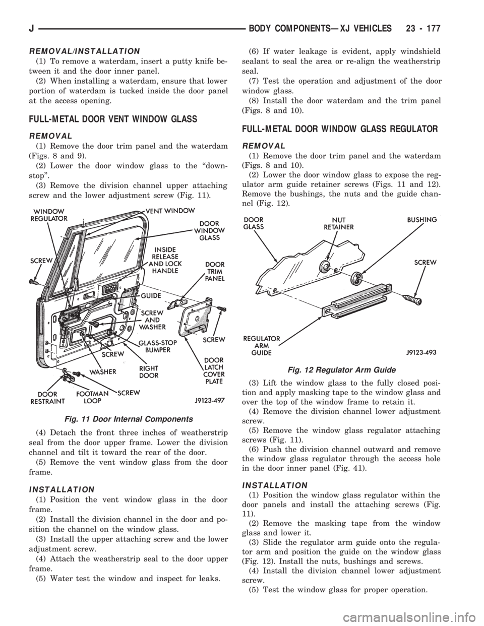
screw and the lower adjustment screw (Fig. 11).
(4) Detach the front three inches of weatherstrip
seal from the door upper frame. Lower the division
channel and tilt it toward the rear of the door.
(5) Remove the vent window glass from the door
frame.
INSTALLATION
(1) Position the vent window glass in the door
frame.
(2) Install the division channel in the door and po-
sition the channel on the window glass.
(3) Install the upper attaching screw and the lower
adjustment screw.
(4) Attach the weatherstrip seal to the door upper
frame.
(5) Water test the window and inspect for leaks.(6) If water leakage is evident, apply windshield
sealant to seal the area or re-align the weatherstrip
seal.
(7) Test the operation and adjustment of the door
window glass.
(8) Install the door waterdam and the trim panel
(Figs. 8 and 10).
FULL-METAL DOOR WINDOW GLASS REGULATOR
REMOVAL
(1) Remove the door trim panel and the waterdam
(Figs. 8 and 10).
(2) Lower the door window glass to expose the reg-
ulator arm guide retainer screws (Figs. 11 and 12).
Remove the bushings, the nuts and the guide chan-
nel (Fig. 12).
(3) Lift the window glass to the fully closed posi-
tion and apply masking tape to the window glass and
over the top of the window frame to retain it.
(4) Remove the division channel lower adjustment
screw.
(5) Remove the window glass regulator attaching
screws (Fig. 11).
(6) Push the division channel outward and remove
the window glass regulator through the access hole
in the door inner panel (Fig. 41).
INSTALLATION
(1) Position the window glass regulator within the
door panels and install the attaching screws (Fig.
11).
(2) Remove the masking tape from the window
glass and lower it.
(3) Slide the regulator arm guide onto the regula-
tor arm and position the guide on the window glass
(Fig. 12). Install the nuts, bushings and screws.
(4) Install the division channel lower adjustment
screw.
(5) Test the window glass for proper operation.
Fig. 11 Door Internal Components
Fig. 12 Regulator Arm Guide
JBODY COMPONENTSÐXJ VEHICLES 23 - 177
Page 1633 of 1784
(6) Install the door waterdam and the trim panel
(Figs. 8 and 10).
FULL-METAL DOOR WINDOW GLASS
ADJUSTMENT
One adjustment location provides amount of effort
required to raise and lower the door window glass.
The door window glass division channel is adjustable
fore and aft at the lower attaching location.
(1) Remove the door trim panel and the waterdam
(Figs. 8 and 10).
(2) Loosen channel lower adjustment screw and
move the division channel fore or aft to obtain the
desired door window glass operation.
Movement of the division channel fore or aft
will decrease or increase the free-play between
the channels.
(3) Tighten the division channel lower adjustment
screw.
(4) Install the door waterdam and the trim panel
(Figs. 8 and 10).
REMOVAL
(1) Remove the door trim panel and the waterdam
(Figs. 8 and 10).
(2) Remove the window glass down-stop bumper
(Fig. 11).
(3) Remove the screws that attach the regulator
arm guide to the window glass. Remove the screws,
bushings, nuts and the guide from the glass (Fig. 11).
(4) Lower the window glass to the bottom of the
door.
(5) Remove the division channel upper attaching
screw and the lower adjustment screw. Detach the
front 3 inches of window glass weatherstrip seal from
the door upper frame.
(6) Separate the division channel from the front
window glass rubber seal. Pull the division channel
up and in toward the inside of vehicle.
(7) Raise and tilt the window glass toward the
hinge side of the door and disengage it from the rear
channel.
(8) Pull the window glass up and out of the door
panel.
INSTALLATION
(1) Lower the window glass into the door, while in-
serting the window glass into the front and rear
channels.
(2) Slide the window glass downward to the bottom
of the door panel.
(3) Lower the division channel into the door and
position the window glass securely in the channel.
(4) Install the weatherstrip seal in the upper door
frame and install the upper attaching screw and the
lower adjustment screw.(5) Slide the guide onto the regulator arm and po-
sition the guide on the window glass. Install the re-
taining nuts, bushings and screws (Fig. 12).
(6) Install the window glass down-stop bumper
(Fig. 11).
(7) Test the window operation for proper adjust-
ment.
(8) Install the door waterdam and the trim panel
(Fig. 8 and 10).
FULL-METAL DOOR KEY LOCK CYLINDER
REMOVAL
(1) Remove the door trim panel and the waterdam
(Figs. 8 and 10).
(2) Remove the door latch cover screws and remove
the cover (Fig. 11).
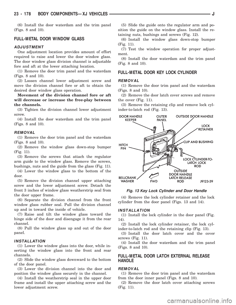
(3) Remove the retaining clip and remove lock cyl-
inder-to-latch rod (Fig. 13).
(4) Remove the lock cylinder retainer and the lock
cylinder from the door panel (Figs. 13 and 14).
INSTALLATION
(1) Install the lock cylinder in the door panel (Fig.
14).
(2) Install the lock cylinder retainer, the lock cyl-
inder-to-latch rod and the retaining clip (Fig. 13).
(3) Install the door latch cover and the cover
screws (Fig. 11).
(4) Install the door waterdam and the trim panel
(Figs. 8 and 10).
FULL-METAL DOOR LATCH EXTERNAL RELEASE
HANDLE
REMOVAL
(1) Remove the door trim panel and the waterdam
from the door inner panel (Figs. 8 and 10).
(2) Remove the door latch cover attaching screws
(Fig. 11).
Fig. 13 Key Lock Cylinder and Door Handle
23 - 178 BODY COMPONENTSÐXJ VEHICLESJ
Page 1638 of 1784
FIXED WINDOW GLASS
INDEX
page page
Fixed Glass Water Leak Detection and Repair . 189
Hard Top Quarter Window Glass............ 188
Rearview Mirror......................... 183
Rearview Mirror Retaining Bracket........... 183
Service Information...................... 183Windshield Frame....................... 184
Windshield Frame Weatherstrip Seal......... 185
Windshield Glass........................ 185
Windshield Reveal Moulding............... 183
SERVICE INFORMATION
The following fixed window service information in-
cludes removal/installation procedures for the:
²windshield reveal moulding,
²rearview mirror,
²windshield frame,
²windshield frame weatherstrip seal,
²windshield glass (using both the short and the ex-
tended installation method), and
²hard top quarter (side) window glass.
WINDSHIELD REVEAL MOULDING
REMOVAL
(1) Disengage the reveal moulding around the pe-
rimeter of the windshield glass with an appropriate
tool.
(2) Remove the mouldings from the windshield
frame.
(3) Inspect the reveal moulding retainers. Replace
the moulding if it has broken, distorted or ineffective
retainers.
INSTALLATION
(1) Position the reveal mouldings on the wind-
shield frame.
(2) Attach the mouldings to the frame by tapping
each moulding with a rubber mallet to seat the re-
tainers.
REARVIEW MIRROR
REMOVAL/INSTALLATION
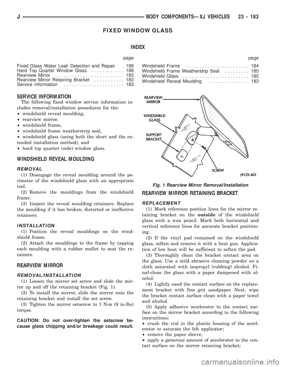
(1) Loosen the mirror set screw and slide the mir-
ror up and off the retaining bracket (Fig. 1).
(2) To install the mirror, slide the mirror onto the
retaining bracket and install the set screw.
(3) Tighten the mirror setscrew to 1 Nzm (9 in-lbs)
torque.
CAUTION: Do not over-tighten the setscrew be-
cause glass chipping and/or breakage could result.
REARVIEW MIRROR RETAINING BRACKET
REPLACEMENT
(1) Mark reference position lines for the mirror re-
taining bracket on theoutsideof the windshield
glass with a wax pencil. Mark both horizontal and
vertical reference lines for accurate bracket position-
ing.
(2) If the vinyl pad remained on the windshield
glass, soften and remove it with a heat gun. Applica-
tion of low heat will be sufficient to soften the pad.
(3) Thoroughly clean the bracket contact area on
the glass. Use a mild abrasive cleaning powder on a
cloth saturated with isopropyl (rubbing) alcohol. Fi-
nal-clean the glass with a paper dampened with al-
cohol.
(4) Lightly sand the contact surface on the replace-
ment bracket with fine grit sandpaper. Next, wipe
the bracket contact surface clean with a paper towel
and alcohol.
(5) Apply adhesive accelerator to the contact sur-
face on the mirror bracket according to the following
instructions:
²crush the vial in the plastic housing of the accel-
erator to saturate the felt applicator;
²remove the paper sleeve;
²apply a generous amount of accelerator to the con-
tact surface on the mirror retaining bracket;
Fig. 1 Rearview Mirror Removal/Installation
JBODY COMPONENTSÐXJ VEHICLES 23 - 183
Page 1680 of 1784
COMPRESSOR OVERHAUL
INDEX
page page
Compressor............................. 17
Compressor Isolation...................... 17
Description............................. 17Magnetic Clutch......................... 18
Purging Compressor of Air................. 17
DESCRIPTION
The A/C system uses a Sanden compressor. This
compressor is a 7 piston design. Designated the SD-
709, the compressor is mounted on the front right
side of the engine and is driven by a serpentine belt.
System lubrication is provided by 135cc615cc (4.6
cu. in.60.5 cu. in.) of 500 viscosity refrigerant oil.
The clutch used on the compressor consists of 3 ba-
sic components: the pulley, front plate and the field
coil. The pulley and field coil are attached to the
front head of the compressor with tapered snap rings.
The hub is keyed to the compressor shaft and is re-
tained on the shaft with a self-locking nut. Special
service tools are required to remove and install the
clutch plate on the compressor shaft.
COMPRESSOR ISOLATION
It is not necessary to discharge the system for com-
pressor removal. The compressor can be isolated from
the remainder of the system and eliminate the need
for recharging when performing compressor service.
(1) Connect pressure gauge and manifold.
(2) Close both gauge hand valves.
(3) Mid-position both service valves.
WARNING: USE EXTREME CAUTION WHEN THE
ENGINE IS OPERATING. DO NOT STAND IN A DI-
RECT LINE WITH THE FAN. DO NOT PUT YOUR
HANDS NEAR THE PULLEYS, BELTS OR FAN. DO
NOT WEAR LOOSE CLOTHING.
(4) Start the engine and operate the air condition-
ing system.
(5) Turn the suction service valve slowly clockwise
toward the front seated position.
(6) When pressure drops to zero, stop the engine
and compressor and quickly finish front-seating the
suction service valve.
(7) Front-seat the discharge service valve.
(8) Loosen the oil level check plug slowly to re-
lease any internal pressure in the compressor.
The compressor is now isolated from the remainder
of the system.
The service valves can be removed from the com-
pressor.
PURGING COMPRESSOR OF AIR
The compressor must be purged of air whenever it
has been isolated for an oil level check or other ser-
vice procedures without discharging the entire sys-
tem.
(1) Cap the service gauge ports on both of the ser-
vice valves.
(2) Back-seat the suction service valve to allow the
system refrigerant to enter the compressor.
(3) Place the discharge service valve in the mid-po-
sition or cracked-position.
(4) Loosen the discharge service valve gauge port
cap to permit the refrigerant to force any air out of
the compressor.
(5) Back-seat the discharge service valve and
tighten the gauge port cap.
(6) The compressor is now ready for service.
COMPRESSOR
REMOVAL
(1) Isolate the compressor.
(2) Disconnect negative cable from battery.
(3) Disconnect the clutch lead wire.
(4) Remove the discharge and inlet (suction) ser-
vice valves from the compressor. Plug or tape all the
openings.
(5) Remove the serpentine drive belt (refer to
Group 7, Cooling System for the proper procedure).
(6) Remove the bolts and lift the compressor from
the mounting bracket (Figs. 1 and 2).
INSTALLATION
If a replacement compressor is being installed;
check the oil level. Add or subtract oil as neces-
sary and install the magnetic clutch on the com-
pressor.
(1) If the mounting bracket was removed, install
the bracket to the block. Tighten the mounting bolts
to 27 NIm (20 ft. lbs.) torque.
(2) Install the compressor on the mounting
bracket. Tighten the bolts to 27 NIm (20 ft. lbs.)
torque.
(3) Install the serpentine drive belt (refer to Group
7, Cooling System for the proper procedure).
(4) Tighten the serpentine drive belt to the speci-
fied tension.
²New belt tensionÐ800-900 N (180-200 lb-f).
JHEATING AND AIR CONDITIONING 24 - 17
Page 1696 of 1784
EVAPORATOR/BLOWER HOUSING
REMOVAL
(1) Disconnect negative cable from battery.
(2) Discharge the A/C system as described in this
section and disconnect the A/C hoses from the expan-
sion valve.
(3) Disconnect the blower motor wires and the vent
tube.
(4) If equipped with center console remove the con-
sole as follows:
(a) MANUAL TRANSMISSIONÐRemove shift
knob, boot and bezel.
(b) AUTOMATIC TRANSMISSIONÐRemove
shift handle by pulling up. Remove the shift bezel.
(c) POWER MIRRORSÐPry mirror switch out of
console cover (Fig. 13) and disconnect switch con-
nector (Fig. 14).
(d) Remove console cover screws (Fig. 14).
(e) Remove console cover from base (Fig. 15).
(f) Remove console base.
(5) Remove the lower instrument panel.
(6) Disconnect the electrical connections at the
blower motor resistors and the A/C thermostat. Dis-
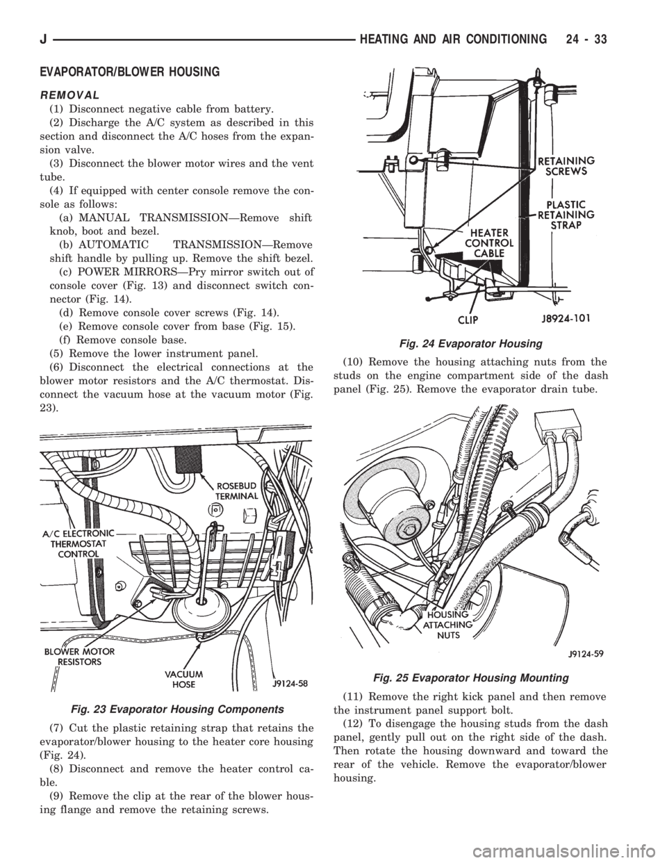
connect the vacuum hose at the vacuum motor (Fig.
23).
(7) Cut the plastic retaining strap that retains the
evaporator/blower housing to the heater core housing
(Fig. 24).
(8) Disconnect and remove the heater control ca-
ble.
(9) Remove the clip at the rear of the blower hous-
ing flange and remove the retaining screws.(10) Remove the housing attaching nuts from the
studs on the engine compartment side of the dash
panel (Fig. 25). Remove the evaporator drain tube.
(11) Remove the right kick panel and then remove
the instrument panel support bolt.
(12) To disengage the housing studs from the dash
panel, gently pull out on the right side of the dash.
Then rotate the housing downward and toward the
rear of the vehicle. Remove the evaporator/blower
housing.
Fig. 23 Evaporator Housing Components
Fig. 24 Evaporator Housing
Fig. 25 Evaporator Housing Mounting
JHEATING AND AIR CONDITIONING 24 - 33
Page 1705 of 1784
INSTALLATION
(1) When installing a replacement temperature
control thermostat, insert the capillary tube into the
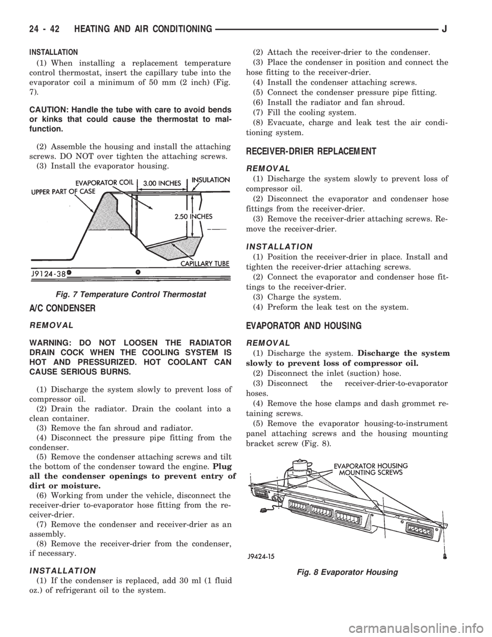
evaporator coil a minimum of 50 mm (2 inch) (Fig.
7).
CAUTION: Handle the tube with care to avoid bends
or kinks that could cause the thermostat to mal-
function.
(2) Assemble the housing and install the attaching
screws. DO NOT over tighten the attaching screws.
(3) Install the evaporator housing.
A/C CONDENSER
REMOVAL
WARNING: DO NOT LOOSEN THE RADIATOR
DRAIN COCK WHEN THE COOLING SYSTEM IS
HOT AND PRESSURIZED. HOT COOLANT CAN
CAUSE SERIOUS BURNS.
(1) Discharge the system slowly to prevent loss of
compressor oil.
(2) Drain the radiator. Drain the coolant into a
clean container.
(3) Remove the fan shroud and radiator.
(4) Disconnect the pressure pipe fitting from the
condenser.
(5) Remove the condenser attaching screws and tilt
the bottom of the condenser toward the engine.Plug
all the condenser openings to prevent entry of
dirt or moisture.
(6) Working from under the vehicle, disconnect the
receiver-drier to-evaporator hose fitting from the re-
ceiver-drier.
(7) Remove the condenser and receiver-drier as an
assembly.
(8) Remove the receiver-drier from the condenser,
if necessary.
INSTALLATION
(1) If the condenser is replaced, add 30 ml (1 fluid
oz.) of refrigerant oil to the system.(2) Attach the receiver-drier to the condenser.
(3) Place the condenser in position and connect the
hose fitting to the receiver-drier.
(4) Install the condenser attaching screws.
(5) Connect the condenser pressure pipe fitting.
(6) Install the radiator and fan shroud.
(7) Fill the cooling system.
(8) Evacuate, charge and leak test the air condi-
tioning system.
RECEIVER-DRIER REPLACEMENT
REMOVAL
(1) Discharge the system slowly to prevent loss of
compressor oil.
(2) Disconnect the evaporator and condenser hose
fittings from the receiver-drier.
(3) Remove the receiver-drier attaching screws. Re-
move the receiver-drier.
INSTALLATION
(1) Position the receiver-drier in place. Install and
tighten the receiver-drier attaching screws.
(2) Connect the evaporator and condenser hose fit-
tings to the receiver-drier.
(3) Charge the system.
(4) Preform the leak test on the system.
EVAPORATOR AND HOUSING
REMOVAL
(1) Discharge the system.Discharge the system
slowly to prevent loss of compressor oil.
(2) Disconnect the inlet (suction) hose.
(3) Disconnect the receiver-drier-to-evaporator
hoses.
(4) Remove the hose clamps and dash grommet re-
taining screws.
(5) Remove the evaporator housing-to-instrument
panel attaching screws and the housing mounting
bracket screw (Fig. 8).
Fig. 7 Temperature Control Thermostat
Fig. 8 Evaporator Housing
24 - 42 HEATING AND AIR CONDITIONINGJ
Page 1706 of 1784
(6) Lower the evaporator housing and pull the
hoses and hose grommet through the dash opening.
The blower motor, blower motor housing, evapora-
tor core, control switches and expansion valve can all
be serviced after removing the evaporator housing
(Fig. 9).
INSTALLATION
(1) If the evaporator is replaced, add 30 ml (1 fluid
oz.) of refrigerant oil to the system.
(2) Push the hoses through the grommet openings
and install the hose grommet by pushing it toward
the engine compartment.
(3) Install the hose grommet attaching screws.
(4) Raise the evaporator housing. Install the evap-
orator housing-to- instrument panel attaching screws
and the evaporator housing mounting bracket screw.
(5) Install the hose clamps.
(6) Connect the receiver-drier hoses.
(7) Connect the inlet (suction) hose.
(8) Evacuate, charge and leak test the system.
EXPANSION (H) VALVE
REMOVAL
(1) Discharge the system slowly to prevent loss of
compressor oil.
(2) Remove the evaporator housing.
(3) Remove the insulation wrapped around the suc-
tion hose fitting, expansion valve and evaporator
tubing.(4) Mark the capillary tube location on the evapo-
rator tubing.
(5) Disconnect the inlet and outlet hose fittings,
and remove the capillary tube clamp.
(6) Disconnect and remove the expansion valve.
INSTALLATION
(1) Clean the evaporator tubing to provide a posi-
tive metal-to-metal contact for the replacement ex-
pansion valve capillary tube.
(2) Install the replacement expansion valve.
(3) Clamp the capillary tube at the marked loca-
tion on the evaporator tubing.
(4) Connect the inlet and outlet hose fittings.The
capillary tube must be securely clamped and
have positive metal-to-metal contact with the
evaporator tubing.
(5) Wrap the expansion valve, inlet hose fitting
and capillary tube with insulation.
(6) Install the evaporator housing.
(7) Evacuate, charge and leak test the system.
A/C BLOWER MOTOR
It is not necessary to discharge the system to ser-
vice the blower motor. The evaporator housing need
only be lowered for access to the blower motor at-
taching screws.
JHEATING AND AIR CONDITIONING 24 - 43