1994 JEEP CHEROKEE lock
[x] Cancel search: lockPage 418 of 1784
(2) Remove the windshield holddown bolts in the
lower corners of the instrument panel.
(3) Remove wiper motor mounting screws (Fig. 4).
(4) Remove wiper motor harness retaining clip lo-
cated on bottom of windshield.
(5) Disconnect the wiper linkage drive arm (Fig. 5)
(6) Grasp the motor and pull the motor and drive
arm out of the access hole (Fig. 6).
(7) Pry the drive arm off the motor pivot. DO NOT
remove the pivot attaching nut (Fig. 7).
(8) Remove 2 screws holding intermittent wipe
module bracket to bottom of instrument panel.
(9) Reach up behind instrument panel and discon-
nect wiper motor harness.
(10) Remove wiper motor.
INSTALLATION
(1) Install wire harness through hole in top of in-
strument panel.
(2) Connect wiper motor connector behind instru-
ment panel.
(3) Install intermittent wipe module bracket to
bottom of instrument panel.
(4) Turn wipers on to allow motor to cycle to park
position.
(5) Install wiper linkage drive arm onto motor
(Fig. 8).
(6) Install motor and drive arm in the windshield
frame.
(7) Connect wiper linkage drive arm to pivot shaft
(Fig. 9).
(8) Install motor mounting screws. Tighten screws
to 10.5 Nzm (96 in. lbs.).
(9) Install wire harness retaining clip on bottom of
windshield.
Be sure wire harness is not pinched or cut when
windshield frame is rotated to upright position.
(10) Raise windshield to upright position and in-
stall left and right windshield holddown bolts.
(11) Install the necessary top components on wind-
shield frame.
WASHER PUMP REPLACEMENT
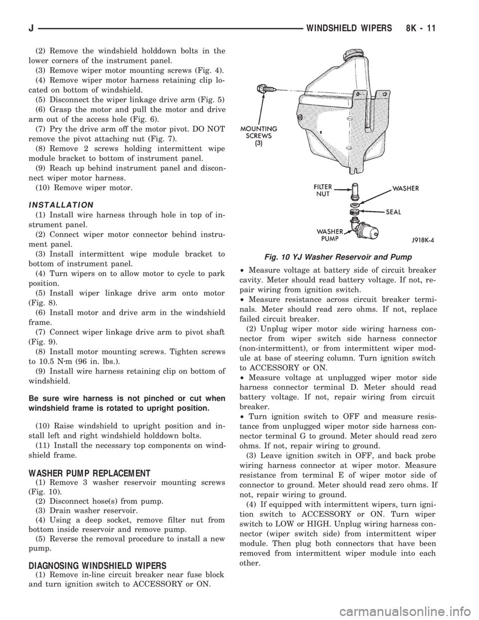
(1) Remove 3 washer reservoir mounting screws
(Fig. 10).
(2) Disconnect hose(s) from pump.
(3) Drain washer reservoir.
(4) Using a deep socket, remove filter nut from
bottom inside reservoir and remove pump.
(5) Reverse the removal procedure to install a new
pump.
DIAGNOSING WINDSHIELD WIPERS
(1) Remove in-line circuit breaker near fuse block
and turn ignition switch to ACCESSORY or ON.²Measure voltage at battery side of circuit breaker
cavity. Meter should read battery voltage. If not, re-
pair wiring from ignition switch.
²Measure resistance across circuit breaker termi-
nals. Meter should read zero ohms. If not, replace
failed circuit breaker.
(2) Unplug wiper motor side wiring harness con-
nector from wiper switch side harness connector
(non-intermittent), or from intermittent wiper mod-
ule at base of steering column. Turn ignition switch
to ACCESSORY or ON.
²Measure voltage at unplugged wiper motor side
harness connector terminal D. Meter should read
battery voltage. If not, repair wiring from circuit
breaker.
²Turn ignition switch to OFF and measure resis-
tance from unplugged wiper motor side harness con-
nector terminal G to ground. Meter should read zero
ohms. If not, repair wiring to ground.
(3) Leave ignition switch in OFF, and back probe
wiring harness connector at wiper motor. Measure
resistance from terminal E of wiper motor side of
connector to ground. Meter should read zero ohms. If
not, repair wiring to ground.
(4) If equipped with intermittent wipers, turn igni-
tion switch to ACCESSORY or ON. Turn wiper
switch to LOW or HIGH. Unplug wiring harness con-
nector (wiper switch side) from intermittent wiper
module. Then plug both connectors that have been
removed from intermittent wiper module into each
other.
Fig. 10 YJ Washer Reservoir and Pump
JWINDSHIELD WIPERS 8K - 11
Page 422 of 1784
WIPER CONTROL SWITCH REPLACEMENT
(1) Disconnect negative cable from battery.
(2) Remove horn button with a push and turn mo-
tion.
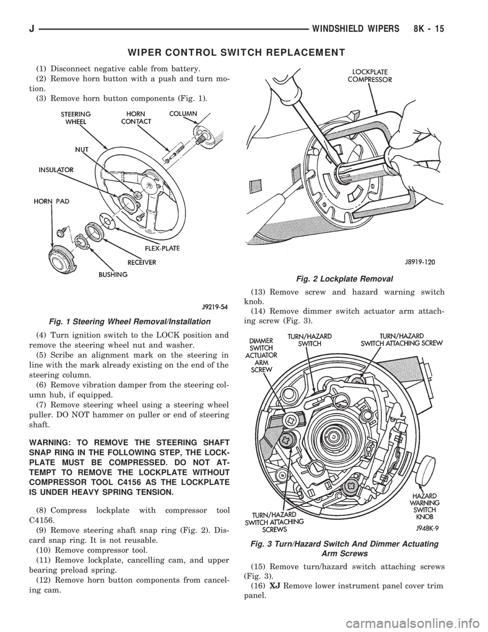
(3) Remove horn button components (Fig. 1).
(4) Turn ignition switch to the LOCK position and
remove the steering wheel nut and washer.
(5) Scribe an alignment mark on the steering in
line with the mark already existing on the end of the
steering column.
(6) Remove vibration damper from the steering col-
umn hub, if equipped.
(7) Remove steering wheel using a steering wheel
puller. DO NOT hammer on puller or end of steering
shaft.
WARNING: TO REMOVE THE STEERING SHAFT
SNAP RING IN THE FOLLOWING STEP, THE LOCK-
PLATE MUST BE COMPRESSED. DO NOT AT-
TEMPT TO REMOVE THE LOCKPLATE WITHOUT
COMPRESSOR TOOL C4156 AS THE LOCKPLATE
IS UNDER HEAVY SPRING TENSION.
(8) Compress lockplate with compressor tool
C4156.
(9) Remove steering shaft snap ring (Fig. 2). Dis-
card snap ring. It is not reusable.
(10) Remove compressor tool.
(11) Remove lockplate, cancelling cam, and upper
bearing preload spring.
(12) Remove horn button components from cancel-
ing cam.(13) Remove screw and hazard warning switch
knob.
(14) Remove dimmer switch actuator arm attach-
ing screw (Fig. 3).
(15) Remove turn/hazard switch attaching screws
(Fig. 3).
(16)XJRemove lower instrument panel cover trim
panel.
Fig. 1 Steering Wheel Removal/Installation
Fig. 2 Lockplate Removal
Fig. 3 Turn/Hazard Switch And Dimmer Actuating
Arm Screws
JWINDSHIELD WIPERS 8K - 15
Page 424 of 1784
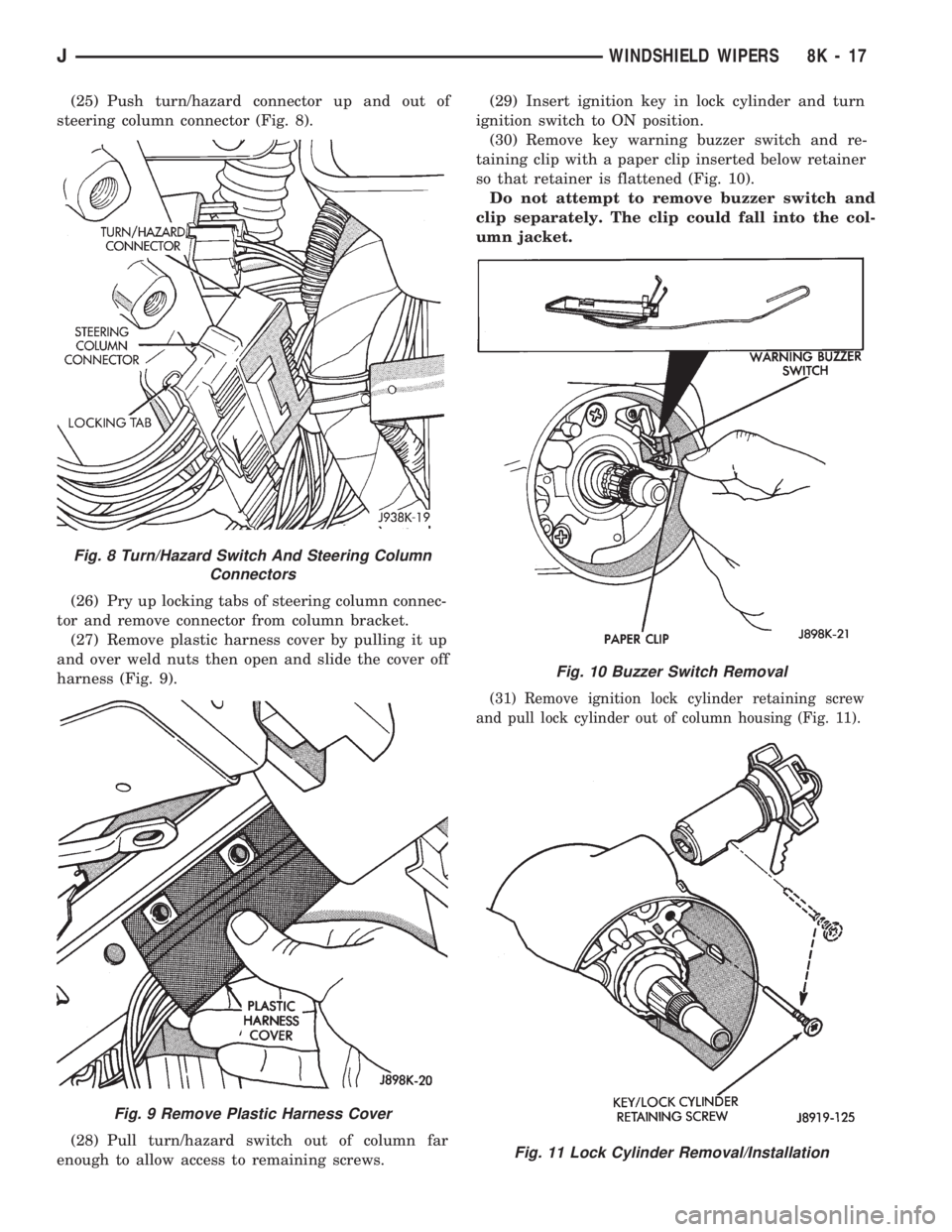
(25) Push turn/hazard connector up and out of
steering column connector (Fig. 8).
(26) Pry up locking tabs of steering column connec-
tor and remove connector from column bracket.
(27) Remove plastic harness cover by pulling it up
and over weld nuts then open and slide the cover off
harness (Fig. 9).
(28) Pull turn/hazard switch out of column far
enough to allow access to remaining screws.(29) Insert ignition key in lock cylinder and turn
ignition switch to ON position.
(30) Remove key warning buzzer switch and re-
taining clip with a paper clip inserted below retainer
so that retainer is flattened (Fig. 10).
Do not attempt to remove buzzer switch and
clip separately. The clip could fall into the col-
umn jacket.
(31) Remove ignition lock cylinder retaining screw
and pull lock cylinder out of column housing (Fig. 11).
Fig. 8 Turn/Hazard Switch And Steering Column
Connectors
Fig. 9 Remove Plastic Harness Cover
Fig. 10 Buzzer Switch Removal
Fig. 11 Lock Cylinder Removal/Installation
JWINDSHIELD WIPERS 8K - 17
Page 425 of 1784
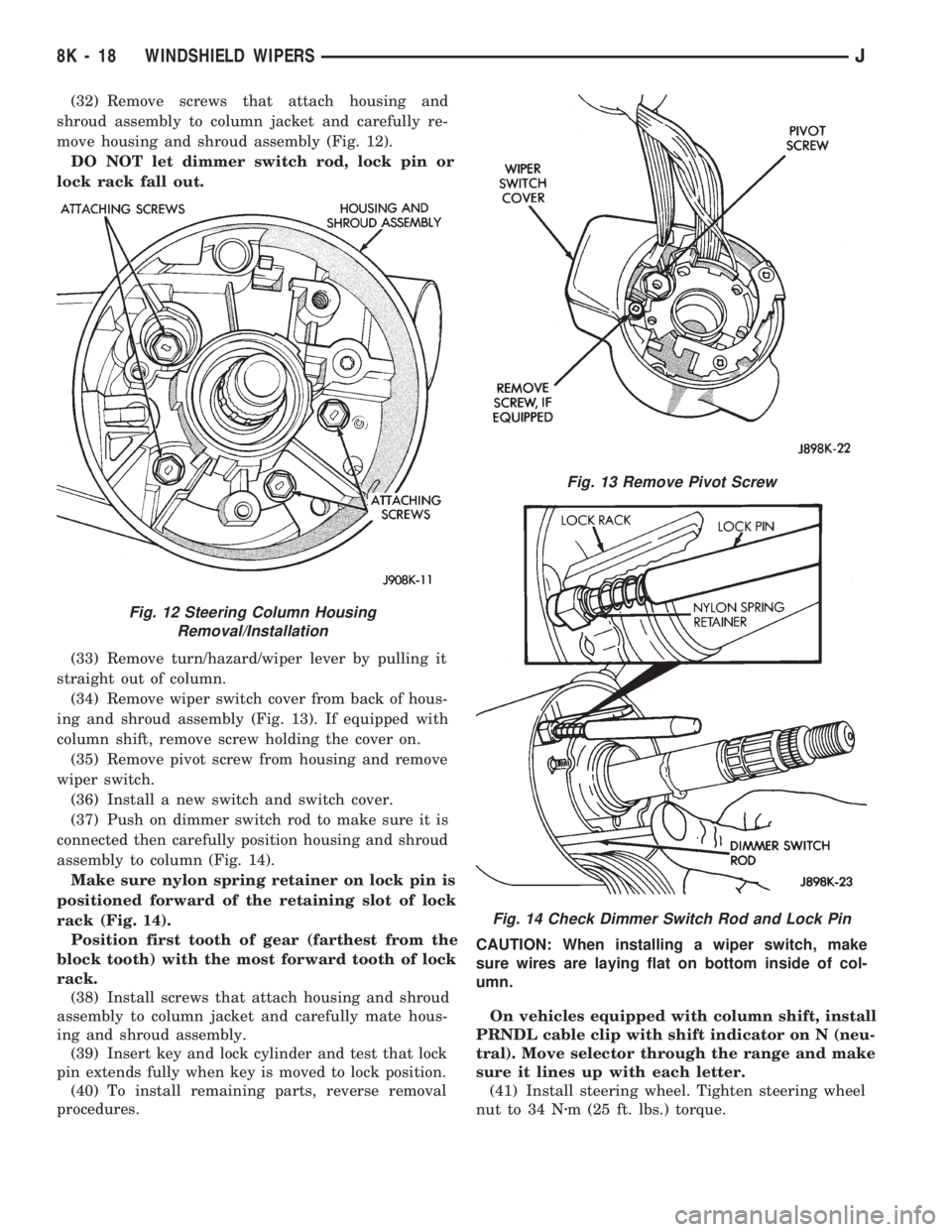
(32) Remove screws that attach housing and
shroud assembly to column jacket and carefully re-
move housing and shroud assembly (Fig. 12).
DO NOT let dimmer switch rod, lock pin or
lock rack fall out.
(33) Remove turn/hazard/wiper lever by pulling it
straight out of column.
(34) Remove wiper switch cover from back of hous-
ing and shroud assembly (Fig. 13). If equipped with
column shift, remove screw holding the cover on.
(35) Remove pivot screw from housing and remove
wiper switch.
(36) Install a new switch and switch cover.
(37) Push on dimmer switch rod to make sure it is
connected then carefully position housing and shroud
assembly to column (Fig. 14).
Make sure nylon spring retainer on lock pin is
positioned forward of the retaining slot of lock
rack (Fig. 14).
Position first tooth of gear (farthest from the
block tooth) with the most forward tooth of lock
rack.
(38) Install screws that attach housing and shroud
assembly to column jacket and carefully mate hous-
ing and shroud assembly.
(39) Insert key and lock cylinder and test that lock
pin extends fully when key is moved to lock position.
(40) To install remaining parts, reverse removal
procedures.CAUTION: When installing a wiper switch, make
sure wires are laying flat on bottom inside of col-
umn.
On vehicles equipped with column shift, install
PRNDL cable clip with shift indicator on N (neu-
tral). Move selector through the range and make
sure it lines up with each letter.
(41) Install steering wheel. Tighten steering wheel
nut to 34 Nzm (25 ft. lbs.) torque.
Fig. 12 Steering Column Housing
Removal/Installation
Fig. 13 Remove Pivot Screw
Fig. 14 Check Dimmer Switch Rod and Lock Pin
8K - 18 WINDSHIELD WIPERSJ
Page 445 of 1784
UNDERHOOD LAMP BULB REPLACEMENT
REMOVALÐALL VEHICLES
(1) Disconnect the wire harness connector from the
underhood lamp.
(2) Rotate the bulb counter-clockwise and remove
it from the lamp base socket.
INSTALLATIONÐALL VEHICLES
(1) Insert a replacement bulb in the lamp base
socket and rotate it clockwise.
(2) Connect the wire harness connector to the
lamp.
UNDERHOOD LAMP REPLACEMENT
REMOVALÐALL VEHICLES
(1) Disconnect the wire harness connector from the
lamp.(2) Rotate the bulb counter-clockwise and remove
it from the lamp base socket.
(3) Remove the screw that attaches the lamp re-
flector and support bracket to the hood inner panel.
(4) Remove the lamp from the hood inner panel.
INSTALLATIONÐALL VEHICLES
(1) Position the underhood lamp on the hood inner
panel.
(2) Install the attaching screw through the lamp
and into the hood panel. Tighten the screw securely.
(3) Insert a replacement bulb in the lamp base
socket and rotate it clockwise.
(4) Connect the wire harness connector to the
lamp.
8L - 18 LAMPSJ
Page 446 of 1784
INTERIOR LAMPS
INDEX
page page
Dome Lamp Replacement.................. 20
Dome/Courtesy Lamp Service Information...... 19
Dome/Courtesy Lamp Trouble Diagnosis....... 19
Hardtop Dome/Cargo Lamp Bulb ReplacementÐYJ
Vehicles.............................. 20Illuminated Entry System Service Information . . . 20
Illuminated Entry System Trouble Diagnosis.... 21
Lighted Vanity Mirror...................... 19
Lighted Vanity Mirror Trouble Diagnosis....... 19
Overhead ConsoleÐXJ Vehicles............. 20
DOME/COURTESY LAMP SERVICE INFORMATION
XJ VEHICLES
Voltage is applied at all times via the dome lamp
fuse to each of the interior lamp bulbs. The interior
lamp bulbs illuminate when they are connected to
body ground via the switch:
²headlamp switch,
²glove box switch,
²door pillar switch, and
²liftgate switch (if the cargo lamp is ON.)
If equipped with Security Alarm Module, refer to
Group 8QÐVehicle Theft Security System.
YJ VEHICLES
The dome/cargo and courtesy lamps are controlled
via ON/OFF switches. The ON/OFF switches are in
the lamp ground circuits. Voltage via the dome/cour-
tesy lamp fuse is applied directly to the lamp bulbs.
When either door is opened, the door pillar switch
contacts close and provide a direct path to vehicle
body ground.
The cargo/cargo and courtesy lamps can also be
turned on via the interior lamp illumination rheo-
stat.
DOME/COURTESY LAMP TROUBLE DIAGNOSIS
ALL LAMPS INOPERATIVE
(1) Rotate the headlamp switch rheostat clockwise.
The lamps should light. If not OK, remove, inspect
and test the dome lamp fuse. Replace if bad.
(2) If the fuse is OK, repair the open circuit in the
wire harness to vehicle body ground.
ONE LAMP INOPERATIVE
(1) Measure the resistance across the bulb holder
terminals. The ohmmeter should indicate zero ohms.
If not, replace the bulb.
(2) Measure the voltage between the voltage side
of the bulb holder and vehicle body ground. The volt-
meter should indicate battery voltage. If not, repair
the open circuit in the wire harness to the splice.
LAMPS INOPERATIVE WITH ONE OR MORE
DOORS OPENED
(1) Remove the inoperative switch from the door
pillar and connect the switch wire directly to ground.
The lamp should light.
(2) If not, check for an open circuit in black
(ground) wire. Repair as necessary. If lamps still do
not light, replace the switch.
LIGHTED VANITY MIRROR
SERVICE INFORMATIONÐXJ VEHICLES
Both the driver and the front passenger sunvisor
can be equipped with a lighted vanity mirror. A
lamp located at each side of the vanity mirror. The
lamps are switched ON automatically when the mir-
ror cover is lifted (Fig. 1).
Voltage is applied directly to the vanity lamp bulbs
via the dome lamp fuse.
LIGHTED VANITY MIRROR TROUBLE DIAGNOSIS
VANITY LAMPS INOPERATIVE
(1) Remove, inspect and test the dome lamp fuse.
Replace if defective.
(2) Test the dome lamp operation. If OK, go to the
next step. If not OK, repair the open circuit in the
wire harness from the splice.
Fig. 1 Lighted Vanity Mirror
JLAMPS 8L - 19
Page 455 of 1784
XJ
REAR WINDOW DEFOGGER SWITCH
REPLACEMENT
(1) Remove the instrument panel bezel; see 8E-In-
strument Panel and Gauges section for the proce-
dure.
(2) Remove the switch housing panel.
(3) Unplug the switch connector. Slightly depress
the switch mounting tabs and remove the switch.
REAR DEFOGGER RELAY
The rear defogger relay is in the relay center. The
relay center is located on the lower instrument panel
trim cover just right of the steering column.
(1) Remove the rear defogger relay (red) from the
relay center (Fig. 2).
(2) To install the relay, reverse the removal proce-
dures.
YJ
REAR WINDOW DEFOGGER SWITCH
REPLACEMENT
(1) Remove 6 shroud screws (Fig. 3).
(2) Slide shroud toward the steering wheel.
(3) Remove 3 screws (Fig. 4).
(4) Unplug the connector from the defogger switch.
(5) Squeeze the ends of the switch to release the
plastic retaining fingers and push outward.
(6) To install, depress the rear window defogger
switch into the bezel until the retaining fingers lock
behind the bezel.
(7) Plug the connector on the switch.(8) Install the bezel with 3 screws.
(9) Install the shroud with 6 screws.
REAR DEFOGGER RELAY
The rear defogger relay is in the relay center. The
relay center is located on the lower instrument panel
trim cover just right of the steering column.
(1) Remove the rear defogger relay (red) from the
relay center (Fig. 2).
(2) To install the relay, reverse the removal proce-
dures.
Fig. 2 Rear Defogger Relay LocationÐXJ
Fig. 3 Instrument Shroud Removal/InstallationÐYJ
Fig. 4 Defogger SwitchÐYJ
8N - 4 REAR WINDOW DEFOGGERJ
Page 456 of 1784
POWER DOOR LOCKS
CONTENTS
page page
KEYLESS ENTRY........................ 8POWER LOCKS......................... 1
POWER LOCKS
INDEX
page page
Actuator Motor Stall Test.................... 6
Description.............................. 1
Diagnosing Power Door Locks............... 1
General................................. 1Liftgate Lock Cylinder Replacement............ 7
Solenoid and Latch Assembly Replacement..... 6
Switch Replacement....................... 6
GENERAL
The door lock actuators, including liftgate, are con-
trolled by two-way switches. To lock the doors, push
down on either switch. To unlock doors from inside
the vehicle push upward on either switch.
The power door locks do not lock or unlock the
doors from outside the vehicle. Insert the key into
the lock cylinder to lock or unlock each individual
door.
DESCRIPTION
The door locks are operated by reversible motors
that receive voltage from fuse #13 in the fuse panel.
Voltage is applied to the driver's side door lock
switch and the passenger's side door lock switch
through the #9 fuse. With the driver's side door lock
switch in LOCK, voltage is applied through the
switch to the door lock relay coil. The relay coil is
energized which closes the circuit from the circuit
breaker to the lock motor. The motor is grounded by
the unlock relay.
The passenger's side door lock window switch oper-
ates the same as the driver's door switch. The volt-
age and ground paths are reversed to unlock the
doors.
The power door lock operates with battery power
and, therefore, is independent of the ignition switch.
DIAGNOSING POWER DOOR LOCKS
If vehicle has Keyless Entry and the door locks op-
erate properly using door switches but do not work
with transmitter, refer to Keyless Entry in this
group.
NO DOOR LOCKS OPERATE USING DOOR
LOCK SWITCHES
(1) Inspect fuse #13. Replace if necessary. If OK,
measure voltage at battery side of fuse. There should
be 12 volts. If not, repair open from Power Distribu-
tion Center.
(2) Remove door switch and measure voltage at
terminal 1. Meter should read battery voltage. If not,
repair open to #9 fuse.
(3) The power window relays are in the relay cen-
ter. The relay center is located on the lower instru-
ment panel trim cover just right of the steering
column (Fig. 1). Remove both relays.
(4) Measure resistance between lock and unlock re-
lay terminal 4 (87A) and ground. Meter should read
zero ohms. If not, repair open to ground.
(5) Measure voltage at terminal 5 (87) of both the
lock and unlock relays. Meter should read battery
voltage. If OK, next step. If not, repair open to cir-
cuit breaker.
(6) Measure resistance at terminal 2 (85) of both
the lock and unlock relays. Meter should read zero
ohms. If not, repair open to ground.
(7) Hold driver's side switch in LOCK position.
Measure voltage at lock relay terminal 1 (86). Meter
should read battery voltage. If OK, next step. If not,
repair open to driver's side switch.
(8) Hold driver's side switch in UNLOCK position.
Measure voltage at unlock relay terminal 1 (86).
Meter should read battery voltage. If OK, next step.
If not, repair open to driver's side switch.
JPOWER DOOR LOCKS 8P - 1