1994 JEEP CHEROKEE lock
[x] Cancel search: lockPage 355 of 1784

INSTRUMENT PANEL REPLACEMENT (Fig. 9)
(1) Disconnect negative cable from battery.
(2) Remove:
²Parking brake release handle
²lower heat/AC duct below steering column
²ash receiver²lower instrument panel (Fig. 10)
²cluster bezel
²cluster assembly
²clock (if equipped)
²radio and heater control panel
²instrument panel switches
²headlamp switch
Fig. 8 Gear Selector Indicator
Fig. 9 Instrument Panel Exploded View
Fig. 10 Lower Instrument Panel Removal/Installation
8E - 8 XJ INSTRUMENT PANEL AND GAUGESJ
Page 363 of 1784

DIAGNOSINGÐALL LAMPS OUT
(1) Inspect fuse #9. Replace as required.
(2) Measure voltage at instrument cluster connec-
tor terminal 20. Meter should read zero ohms. If not,
repair open to ground.
UPSHIFT INDICATOR LAMP
Vehicles equipped with manual transmissions have
an optional upshift indicator lamp. The lamp is con-
trolled by the PCM. The lamp lights to indicate when
the driver should shift to the next highest gear for best
fuel economy. The PCM will turn the lamp off after 3 to
5 seconds if the upshift is not performed. The lamp will
remain off until the vehicle stops accelerating and is
brought back to the range of lamp operation or shifted
into another gear.
The indicator lamp is normally illuminated when
the ignition switch is turned ON and it is turned off
when the engine is started. The lamp will be lighted
during engine operation according to engine speed
and load.
(1) Turn ignition switch to ON.
(2) Ground pin 2 of cluster connector. Lamp should
light. If not, replace bulb. If OK, continue with step 3.
(3) Turn ignition switch to OFF. Check for conti-
nuity between cluster connector pin 2 and pin 54 of
the PCM. If not, repair open. If OK, refer to DRB
scan tool actuator test of upshift indicator.
BRAKE INDICATOR LAMP
The brake indicator is a dual function lamp. It will in-
dicate an unequal pressure condition in the split brake
hydraulic system and it also will indicate when the park-
ing brake is engaged. Separate switches are used for each
indicator lamp function. A switch mounted on the brake
pedal assembly will close a ground circuit whenever the
parking brakes are applied. A second switch is installed
in the brake hydraulic lines near the master cylinder. If
the switch is balanced by equal pressure on both ends of
the switch valve, the valve remains centered and the
lamp remains off. If the valve is shifted by unequal pres-
sure between the front or rear brake hydraulic systems,
the lamp circuit is connected to ground. To make sure
the brake lamp is functional before the vehicle is driven,
it is illuminated through a ground circuit when the igni-
tion switch is turned to the START position.
(1) Turn ignition switch to ON.
(2) Ground pin 1 of the cluster connector. Lamp
should light. If not, replace bulb. If OK, continue
with step 3.
(3) Turn ignition switch to OFF. Check for continuity to
park brake switch and brake warning switch.
MALFUNCTION INDICATOR LAMP (CHECK ENGINE)
The Malfunction Indicator Lamp (Check Engine) il-
luminates each time the ignition switch is turned
ON and stays on for 3 seconds as a bulb test.If the PCM receives an incorrect signal or no signal
from certain sensors or emission related systems the
lamp is turned on (pin 32 of PCM). This is a warning
that the PCM has recorded a system or sensor mal-
function. In some cases when a diagnostic fault is de-
clared the PCM will go into a limp-in mode in an
attempt to keep the system operating. It signals an
immediate need for service.
The lamp also can be used to display diagnostic
trouble codes (DTC). Cycle the ignition switch ON,
OFF, ON, OFF, ON within 5 seconds. This will allow
any DTC's stored in the PCM memory to be dis-
played in a series of flashes representing digits.
(1) Turn ignition switch to ON.
(2) Ground pin 4 of cluster connector. Lamp should
light. If not, replace bulb. If OK, continue with step 3.
(3) Turn ignition switch to OFF. Check for conti-
nuity between cluster connector pin 4 and PCM cav-
ity 32. If OK, replace PCM. If not, repair open.
SEAT BELT REMINDER LAMP
Apply 12 volts to terminal 16 of cluster connector.
Lamp should light. If not, replace bulb. If OK, check
wiring for an open to buzzer module. Refer to Group
8U - Chime/Buzzer Warning Systems.
INSTRUMENT PANEL ILLUMINATION LAMPS
The instrument panel illumination lamps share
two common connections. There is a splice after fuse
#10 that connects the lamps to battery feed. There is
also a splice that connects all lamps to ground. Be-
cause they share these common connection points in
a parallel circuit, the illumination lamps will all
come on at the same time. It also means one or more
lamps can be out without affecting the operation of
the other lamps.
On the battery side of the circuit, the headlamp
switch illumination rheostat/switch and panel lamps
fuse receive battery feed in series from the park/tail
fuse. In the park lamp position, the headlamp switch
completes the circuit from the park/tail fuse to the il-
lumination rheostat/switch and panel lamps fuse.
The illumination rheostat contains a variable resis-
tor that allows the driver to vary illumination inten-
sity from off to full brightness.
DIAGNOSIS
(1) Turn parking lamps ON.
(2) Check fuse #10. Replace as required.
(3) Measure voltage at battery side of fuse #10
with rheostat turned counterclockwise to clockwise
(LO to HI). Meter should read zero volts to battery
voltage. If not, replace headlamp switch.
(4) Measure resistance at ground side of fuse #10
with parking lamps OFF. Meter should read almost
zero ohms (except bulb filament). If not, repair open
to ground. If zero ohms, 12 volt supply wire from fuse
is shorted to ground, repair short.
8E - 16 YJ INSTRUMENT PANEL AND GAUGESJ
Page 369 of 1784

GAUGE PACKAGE GENERAL INFORMATION
The gauge package contains 4 gauges and the 4
wheel drive indicator. The gauges have a common
battery feed from fuse #9 and ignition switch. Al-
though they have separate power sources, the 4
gauges share a common ground connection.
The voltmeter indicates electrical system voltage.
When the engine is not running, the voltage regis-
tered is from the battery. After the engine is started,
charging system voltage is indicated. In the gauge
package, the voltmeter forms a parallel connectionacross the battery feed and ground.
The remaining gauges - oil pressure, fuel and cool-
ant temperature - are connected to individual sender
units. Variable resistors in the senders will change
the amount of current allowed to flow through the
gauge coils. As current flow through the coils varies,
the position of the indicator needle also will vary.
The 4 gauges are connected to battery feed, ground
and the sender units through a printed circuit
mounted on the back of the gauge housing.
GAUGE PACKAGE DIAGNOSIS
ALL GAUGES INOPERATIVE (Fig. 15)
(1) Check the fuse #9. Replace as required.
(2) Turn ignition switch to ON and measure volt-
age at battery side of fuse #9. Meter should read bat-
tery voltage. If not, repair open from ignition switch.
(3) Unplug gauge package connector from gauge
package.
(4) Turn ignition switch to OFF and measure resis-
tance from instrument cluster connector terminals 1
and 13 to a clean chassis ground. Meter should read
zero ohms. If not, repair open to ground.
(5) Turn ignition switch to ON and measure volt-
age at instrument cluster connector terminals 2 and
12. Meter should read battery voltage. If not, repair
open from fuse panel.
ONE GAUGE INOPERATIVE
Does not apply to voltmeter.
OIL PRESSURE SENDER
(1) Turn ignition switch to ON.
(2) Unplug oil pressure sender connector from oil
pressure sender.
(3) Touch connector to engine block (ground).
Gauge should read at low end of scale.
(4) When connector is NOT touching ground (open
circuit) gauge should read at high end of scale. If OK
replace sender. If not, proceed with step 5.
(5) Check circuit between sender and gauge for an
open. Repair as required. If wiring is OK, replace
gauge.
COOLANT TEMPERATURE SENDER
(1) Turn ignition switch to ON.
(2) Unplug coolant temperature sender connector
from coolant temperature sender.
(3) Touch connector to engine block (ground).
Gauge should read at high end of scale.
(4) When connector is NOT touching ground (open
circuit) gauge should read at low end of scale. If OK
replace sender. If not, proceed with step 5.
(5) Check circuit between sender and gauge for an
open. Repair as required. If wiring is OK, replace
gauge.
FUEL GAUGE SENDER
(1) Turn ignition switch to ON.
(2) Separate fuel gauge sender connector from fuel
gauge sender near tank.
(3) Ground the center wire of the body harness
side of the connector. The gauge should read at low
end of scale. If OK, check sending unit (step 4). If
not, check circuit between connector and gauge. Re-
pair as required. If circuit is OK, replace gauge.
(4) Turn ignition switch to OFF.
(5) Measure resistance from fuel gauge sender con-
nector center terminal to a clean chassis ground.
Meter readings should correspond to those shown in
Specifications. If not OK, replace sender. If OK, re-
pair open from fuel gauge sender connector to
ground.
PRINTED CIRCUIT
(1) Turn ignition switch to ON.
(2) Unplug gauge package connector from gauge
package.
(3) Measure resistance from gauge package termi-
nal 12 (fuel and coolant temperature gauge) or from
terminal 2 (voltmeter and oil pressure gauge) to
gauge battery terminal. Meter should read zero
ohms. If not, replace/repair printed circuit.
(4) Measure resistance from gauge package termi-
nal 13 (fuel and coolant temperature gauge) or from
terminal 1 (voltmeter and oil pressure gauge) to
gauge ground terminal. Meter should read zero
ohms. If not, replace/repair printed circuit. If zero
ohms, replace gauge.
GAUGE CALIBRATION VALUES
Use the charts in Specifications. The calibration of
the gauge can be checked. If the indicator needle is
not in the correct position, replace the gauge.
4WD INDICATOR
The four-wheel drive indicator lamp circuit is com-
pleted by the Command-Trac switch located below
the battery.
8E - 22 YJ INSTRUMENT PANEL AND GAUGESJ
Page 377 of 1784
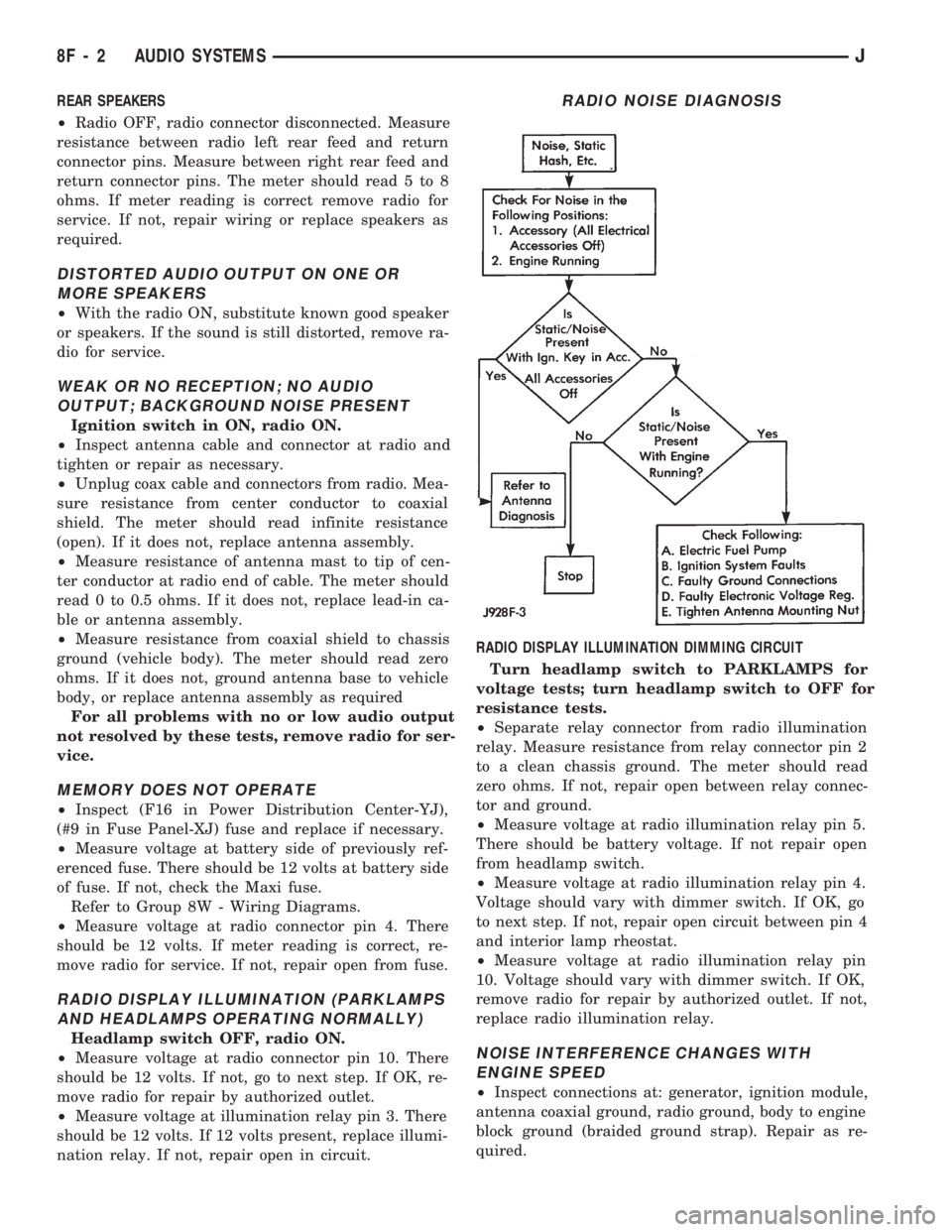
REAR SPEAKERS
²Radio OFF, radio connector disconnected. Measure
resistance between radio left rear feed and return
connector pins. Measure between right rear feed and
return connector pins. The meter should read 5 to 8
ohms. If meter reading is correct remove radio for
service. If not, repair wiring or replace speakers as
required.
DISTORTED AUDIO OUTPUT ON ONE OR
MORE SPEAKERS
²With the radio ON, substitute known good speaker
or speakers. If the sound is still distorted, remove ra-
dio for service.
WEAK OR NO RECEPTION; NO AUDIO
OUTPUT; BACKGROUND NOISE PRESENT
Ignition switch in ON, radio ON.
²Inspect antenna cable and connector at radio and
tighten or repair as necessary.
²Unplug coax cable and connectors from radio. Mea-
sure resistance from center conductor to coaxial
shield. The meter should read infinite resistance
(open). If it does not, replace antenna assembly.
²Measure resistance of antenna mast to tip of cen-
ter conductor at radio end of cable. The meter should
read 0 to 0.5 ohms. If it does not, replace lead-in ca-
ble or antenna assembly.
²Measure resistance from coaxial shield to chassis
ground (vehicle body). The meter should read zero
ohms. If it does not, ground antenna base to vehicle
body, or replace antenna assembly as required
For all problems with no or low audio output
not resolved by these tests, remove radio for ser-
vice.
MEMORY DOES NOT OPERATE
²Inspect (F16 in Power Distribution Center-YJ),
(#9 in Fuse Panel-XJ) fuse and replace if necessary.
²Measure voltage at battery side of previously ref-
erenced fuse. There should be 12 volts at battery side
of fuse. If not, check the Maxi fuse.
Refer to Group 8W - Wiring Diagrams.
²Measure voltage at radio connector pin 4. There
should be 12 volts. If meter reading is correct, re-
move radio for service. If not, repair open from fuse.
RADIO DISPLAY ILLUMINATION (PARKLAMPS
AND HEADLAMPS OPERATING NORMALLY)
Headlamp switch OFF, radio ON.
²Measure voltage at radio connector pin 10. There
should be 12 volts. If not, go to next step. If OK, re-
move radio for repair by authorized outlet.
²Measure voltage at illumination relay pin 3. There
should be 12 volts. If 12 volts present, replace illumi-
nation relay. If not, repair open in circuit.RADIO DISPLAY ILLUMINATION DIMMING CIRCUIT
Turn headlamp switch to PARKLAMPS for
voltage tests; turn headlamp switch to OFF for
resistance tests.
²Separate relay connector from radio illumination
relay. Measure resistance from relay connector pin 2
to a clean chassis ground. The meter should read
zero ohms. If not, repair open between relay connec-
tor and ground.
²Measure voltage at radio illumination relay pin 5.
There should be battery voltage. If not repair open
from headlamp switch.
²Measure voltage at radio illumination relay pin 4.
Voltage should vary with dimmer switch. If OK, go
to next step. If not, repair open circuit between pin 4
and interior lamp rheostat.
²Measure voltage at radio illumination relay pin
10. Voltage should vary with dimmer switch. If OK,
remove radio for repair by authorized outlet. If not,
replace radio illumination relay.NOISE INTERFERENCE CHANGES WITH
ENGINE SPEED
²Inspect connections at: generator, ignition module,
antenna coaxial ground, radio ground, body to engine
block ground (braided ground strap). Repair as re-
quired.
RADIO NOISE DIAGNOSIS
8F - 2 AUDIO SYSTEMSJ
Page 398 of 1784
SERVICE PROCEDURES
INDEX
page page
Servo Cable Replacement................... 9
Speed Control Servo Replacement............ 9Speed Control Switch Replacement............ 9
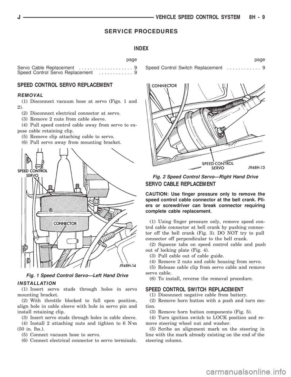
SPEED CONTROL SERVO REPLACEMENT
REMOVAL
(1) Disconnect vacuum hose at servo (Figs. 1 and
2).
(2) Disconnect electrical connector at servo.
(3) Remove 2 nuts from cable sleeve.
(4) Pull speed control cable away from servo to ex-
pose cable retaining clip.
(5) Remove clip attaching cable to servo.
(6) Pull servo away from mounting bracket.
INSTALLATION
(1) Insert servo studs through holes in servo
mounting bracket.
(2) With throttle blocked to full open position,
align hole in cable sleeve with hole in servo pin and
install retaining clip.
(3)
Insert servo studs through holes in cable sleeve.
(4) Install 2 attaching nuts and tighten to 6 Nzm
(50 in. lbs.).
(5) Connect vacuum hose to servo.
(6) Connect electrical connector to servo terminals.
SERVO CABLE REPLACEMENT
CAUTION: Use finger pressure only to remove the
speed control cable connector at the bell crank. Pli-
ers or screwdriver can break connector requiring
complete cable replacement.
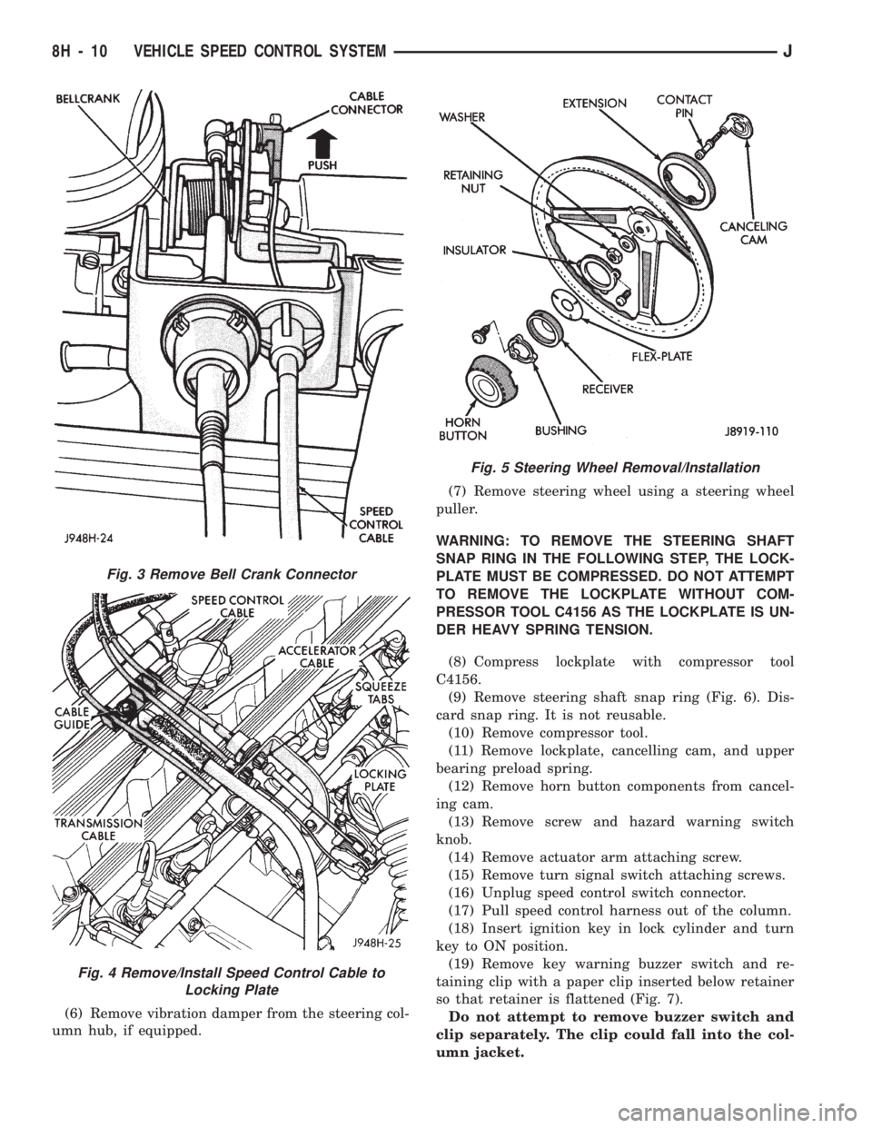
(1) Using finger pressure only, remove speed con-
trol cable connector at bell crank by pushing connec-
tor off the bell crank (Fig. 3). DO NOT try to pull
connector off perpendicular to the bell crank.
(2) Squeeze tabs on speed control cable and push
out of locking plate (Fig. 4).
(3) Pull cable out of cable guide.
(4) Remove 2 nuts and cable housing from servo.
(5) Release cable clip from servo cable and remove
servo cable.
(6) To install, reverse the removal procedure.
SPEED CONTROL SWITCH REPLACEMENT
(1) Disconnect negative cable from battery.
(2) Remove horn button with a push and turn mo-
tion.
(3) Remove horn button components (Fig. 5).
(4) Turn ignition switch to LOCK position and re-
move steering wheel nut and washer.
(5) Scribe an alignment mark on the steering in
line with the mark already existing on the end of the
steering column.
Fig. 2 Speed Control ServoÐRight Hand Drive
Fig. 1 Speed Control ServoÐLeft Hand Drive
JVEHICLE SPEED CONTROL SYSTEM 8H - 9
Page 399 of 1784
(6) Remove vibration damper from the steering col-
umn hub, if equipped.(7) Remove steering wheel using a steering wheel
puller.
WARNING: TO REMOVE THE STEERING SHAFT
SNAP RING IN THE FOLLOWING STEP, THE LOCK-
PLATE MUST BE COMPRESSED. DO NOT ATTEMPT
TO REMOVE THE LOCKPLATE WITHOUT COM-
PRESSOR TOOL C4156 AS THE LOCKPLATE IS UN-
DER HEAVY SPRING TENSION.
(8) Compress lockplate with compressor tool
C4156.
(9) Remove steering shaft snap ring (Fig. 6). Dis-
card snap ring. It is not reusable.
(10) Remove compressor tool.
(11) Remove lockplate, cancelling cam, and upper
bearing preload spring.
(12) Remove horn button components from cancel-
ing cam.
(13) Remove screw and hazard warning switch
knob.
(14) Remove actuator arm attaching screw.
(15) Remove turn signal switch attaching screws.
(16) Unplug speed control switch connector.
(17) Pull speed control harness out of the column.
(18) Insert ignition key in lock cylinder and turn
key to ON position.
(19) Remove key warning buzzer switch and re-
taining clip with a paper clip inserted below retainer
so that retainer is flattened (Fig. 7).
Do not attempt to remove buzzer switch and
clip separately. The clip could fall into the col-
umn jacket.
Fig. 3 Remove Bell Crank Connector
Fig. 4 Remove/Install Speed Control Cable to
Locking Plate
Fig. 5 Steering Wheel Removal/Installation
8H - 10 VEHICLE SPEED CONTROL SYSTEMJ
Page 400 of 1784
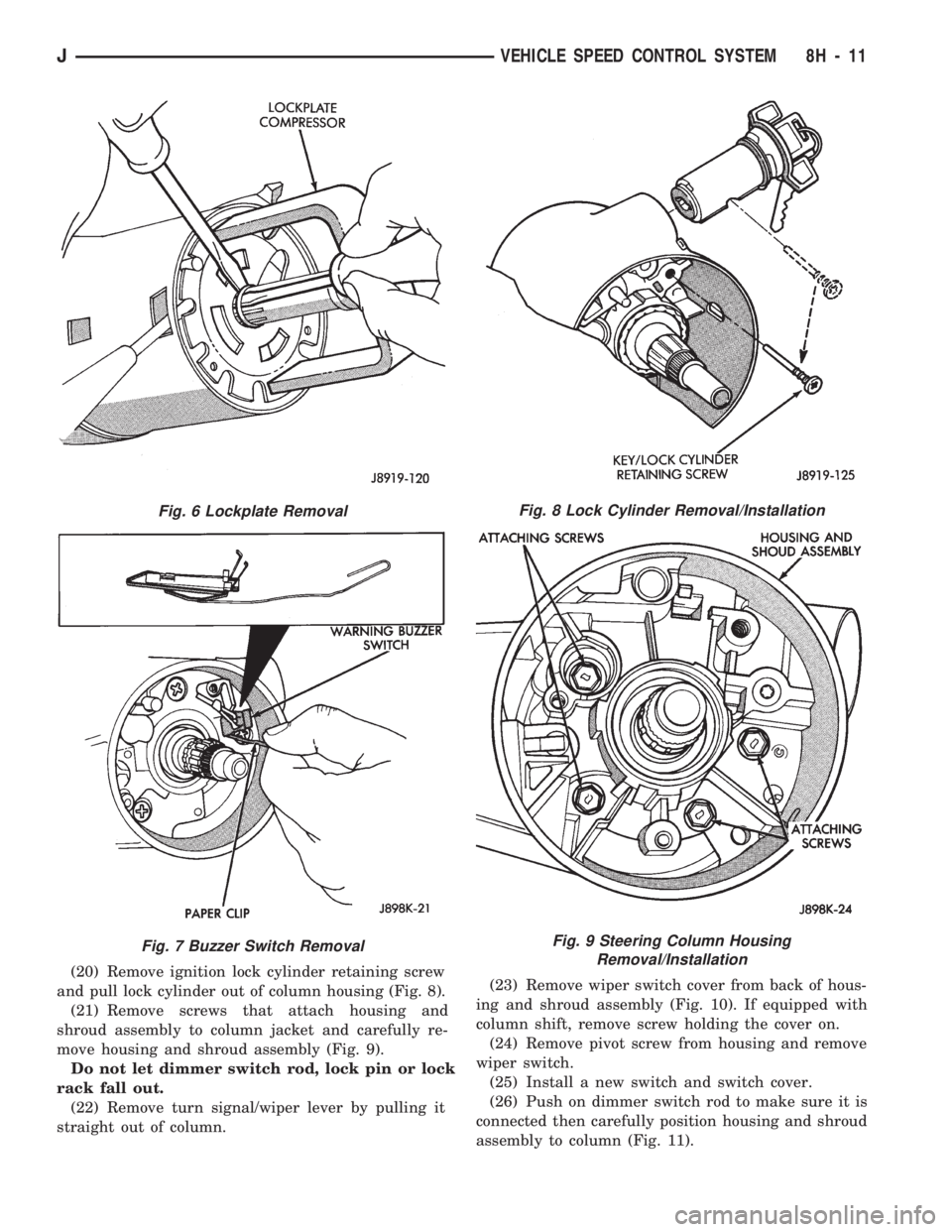
(20) Remove ignition lock cylinder retaining screw
and pull lock cylinder out of column housing (Fig. 8).
(21) Remove screws that attach housing and
shroud assembly to column jacket and carefully re-
move housing and shroud assembly (Fig. 9).
Do not let dimmer switch rod, lock pin or lock
rack fall out.
(22) Remove turn signal/wiper lever by pulling it
straight out of column.(23) Remove wiper switch cover from back of hous-
ing and shroud assembly (Fig. 10). If equipped with
column shift, remove screw holding the cover on.
(24) Remove pivot screw from housing and remove
wiper switch.
(25) Install a new switch and switch cover.
(26) Push on dimmer switch rod to make sure it is
connected then carefully position housing and shroud
assembly to column (Fig. 11).
Fig. 6 Lockplate Removal
Fig. 7 Buzzer Switch Removal
Fig. 8 Lock Cylinder Removal/Installation
Fig. 9 Steering Column Housing
Removal/Installation
JVEHICLE SPEED CONTROL SYSTEM 8H - 11
Page 401 of 1784
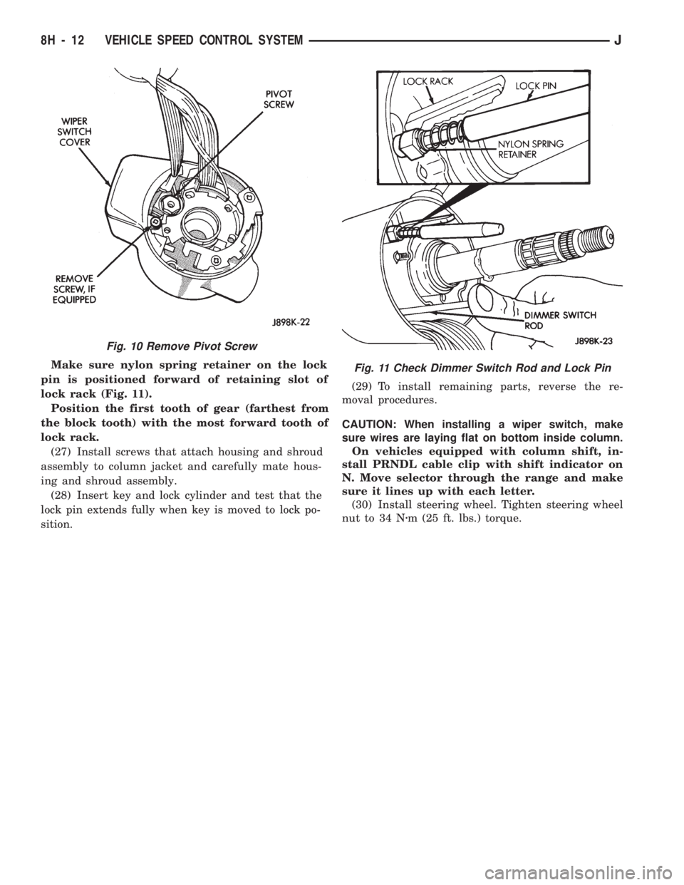
Make sure nylon spring retainer on the lock
pin is positioned forward of retaining slot of
lock rack (Fig. 11).
Position the first tooth of gear (farthest from
the block tooth) with the most forward tooth of
lock rack.
(27) Install screws that attach housing and shroud
assembly to column jacket and carefully mate hous-
ing and shroud assembly.
(28) Insert key and lock cylinder and test that the
lock pin extends fully when key is moved to lock po-
sition.(29) To install remaining parts, reverse the re-
moval procedures.
CAUTION: When installing a wiper switch, make
sure wires are laying flat on bottom inside column.
On vehicles equipped with column shift, in-
stall PRNDL cable clip with shift indicator on
N. Move selector through the range and make
sure it lines up with each letter.
(30) Install steering wheel. Tighten steering wheel
nut to 34 Nzm (25 ft. lbs.) torque.
Fig. 10 Remove Pivot Screw
Fig. 11 Check Dimmer Switch Rod and Lock Pin
8H - 12 VEHICLE SPEED CONTROL SYSTEMJ