1994 JEEP CHEROKEE lock
[x] Cancel search: lockPage 281 of 1784
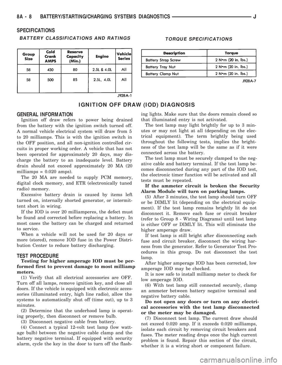
SPECIFICATIONS
IGNITION OFF DRAW (IOD) DIAGNOSIS
GENERAL INFORMATION
Ignition off draw refers to power being drained
from the battery with the ignition switch turned off.
A normal vehicle electrical system will draw from 5
to 20 milliamps. This is with the ignition switch in
the OFF position, and all non-ignition controlled cir-
cuits in proper working order. A vehicle that has not
been operated for approximately 20 days, may dis-
charge the battery to an inadequate level. Battery
drain should not exceed approximately 20 MA (20
milliamps = 0.020 amps).
The 20 MA are needed to supply PCM memory,
digital clock memory, and ETR (electronically tuned
radio) memory.
Excessive battery drain is caused by items left
turned on, internally shorted generator, or intermit-
tent short in wiring.
If the IOD is over 20 milliamperes, the defect must
be found and corrected before replacing a battery. In
most cases the battery can be charged and returned
to service.
When a vehicle will not be used for 20 days or
more (stored), remove IOD fuse in the Power Distri-
bution Center to reduce battery discharging.
TEST PROCEDURE
Testing for higher amperage IOD must be per-
formed first to prevent damage to most milliamp
meters.
(1) Verify that all electrical accessories are OFF.
Turn off all lamps, remove ignition key, and close all
doors. If the vehicle is equipped with electronic acces-
sories (illuminated entry, high line radio), allow the
systems to automatically shut off (time out), up to 3
minutes.
(2) Determine that the underhood lamp is operat-
ing properly, then disconnect or remove bulb.
(3) Disconnect negative cable from battery.
(4) Connect a typical 12-volt test lamp (low watt-
age bulb) between the negative cable clamp and the
battery negative terminal. If equipped with security
alarm, cycle the key in the door to turn off the flash-ing lights. Make sure that the doors remain closed so
that illuminated entry is not activated.
The test lamp may light brightly for up to 3 min-
utes or may not light at all (depending on the elec-
trical equipment). The term brightly being used
throughout the following tests, implies the bright-
ness of the test lamp will be the same as if it were
connected across the battery.
The test lamp must be securely clamped to the neg-
ative cable and battery terminal. If the test lamp be-
comes disconnected during any part of the IOD test,
the electronic timer function will be activated and all
tests must be repeated.
If the ammeter circuit is broken the Security
Alarm Module will turn on parking lamps.
(5) After 3 minutes, the test lamp should turn OFF
or be DIMLY lit (depending on the electrical equip-
ment). If the test lamp remains brightly lit do not
disconnect it. Remove each fuse or circuit breaker
(refer to Group 8 - Wiring Diagrams) until test lamp
is either OFF or DIMLY lit. This will eliminate the
higher amperage draw.
If test lamp is still bright after disconnecting each
fuse and circuit breaker, disconnect the wiring har-
ness from the generator. Refer to Generator Test Pro-
cedures in this group. Do not disconnect the test
lamp.
After higher amperage IOD has been corrected, low
amperage IOD may be checked.
It is now safe to install milliamp meter to check for
low amperage IOD.
(6) With test lamp still connected securely, clamp
an ammeter between battery negative terminal and
negative battery cable.
Do not open any doors or turn on any electri-
cal accessories with the test lamp disconnected
or the meter may be damaged.
(7) Disconnect test lamp. The current draw should
not exceed 0.020 amp. If it exceeds 0.020 milliamps,
isolate each circuit by removing circuit breakers and
fuses. The meter reading drops once the high current
problem is found. Repair this section of the circuit,
whether it is a wiring short or component failure.
BATTERY CLASSIFICATIONS AND RATINGSTORQUE SPECIFICATIONS
8A - 8 BATTERY/STARTING/CHARGING SYSTEMS DIAGNOSTICSJ
Page 284 of 1784
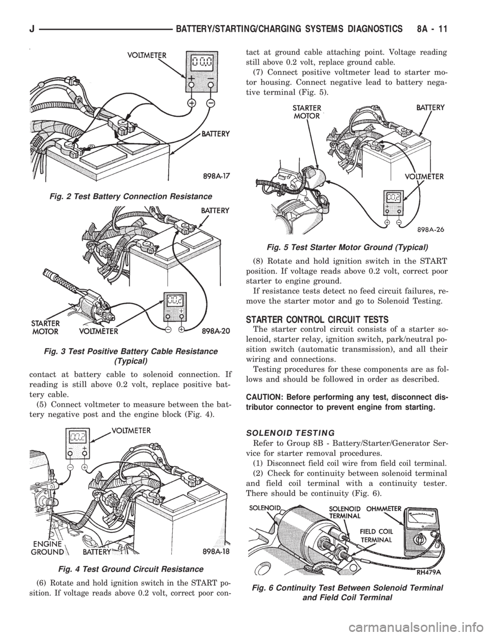
contact at battery cable to solenoid connection. If
reading is still above 0.2 volt, replace positive bat-
tery cable.
(5) Connect voltmeter to measure between the bat-
tery negative post and the engine block (Fig. 4).
(6) Rotate and hold ignition switch in the START po-
sition. If voltage reads above 0.2 volt, correct poor con-tact at ground cable attaching point. Voltage reading
still above 0.2 volt, replace ground cable.
(7) Connect positive voltmeter lead to starter mo-
tor housing. Connect negative lead to battery nega-
tive terminal (Fig. 5).
(8) Rotate and hold ignition switch in the START
position. If voltage reads above 0.2 volt, correct poor
starter to engine ground.
If resistance tests detect no feed circuit failures, re-
move the starter motor and go to Solenoid Testing.
STARTER CONTROL CIRCUIT TESTS
The starter control circuit consists of a starter so-
lenoid, starter relay, ignition switch, park/neutral po-
sition switch (automatic transmission), and all their
wiring and connections.
Testing procedures for these components are as fol-
lows and should be followed in order as described.
CAUTION: Before performing any test, disconnect dis-
tributor connector to prevent engine from starting.
SOLENOID TESTING
Refer to Group 8B - Battery/Starter/Generator Ser-
vice for starter removal procedures.
(1) Disconnect field coil wire from field coil terminal.
(2) Check for continuity between solenoid terminal
and field coil terminal with a continuity tester.
There should be continuity (Fig. 6).
Fig. 2 Test Battery Connection Resistance
Fig. 3 Test Positive Battery Cable Resistance
(Typical)
Fig. 4 Test Ground Circuit Resistance
Fig. 5 Test Starter Motor Ground (Typical)
Fig. 6 Continuity Test Between Solenoid Terminal
and Field Coil Terminal
JBATTERY/STARTING/CHARGING SYSTEMS DIAGNOSTICS 8A - 11
Page 288 of 1784

OPERATIONAL CHECK WITH VOLTMETER
When the ignition switch is turned to the ON po-
sition, battery potential will register on the voltme-
ter. During engine cranking a lower voltage will
appear on the meter. With the engine running, a
voltage reading higher than the first reading (igni-
tion in ON) should register.
DIAGNOSTIC PROCEDURES
If the indicator operates abnormally, or if an un-
dercharged or overcharged battery condition occurs,
the following procedures may be used to diagnose the
charging system.
Remember that an undercharged battery is often
caused by:
²accessories being left on overnight
²or by a defective switch which allows a bulb, such
as a liftgate or glove box light, to stay on (refer to
Ignition Off Draw Diagnosis).
VISUAL INSPECTION
²Inspect condition of battery cable terminals, bat-
tery posts, connections at engine block, starter motor
solenoid and relay. They should be clean and tight.
Repair as required.
²Inspect all fuses in the fuse block for tightness in
receptacles. They should be properly installed and
tight. Repair or replace as required.²Inspect the electrolyte level in the battery and add
water if necessary.
²Inspect generator mounting bolts for tightness. Re-
place or torque bolt as required. Refer to Torque
Specifications in Battery/Starter/Generator Service.
²Inspect generator drive belt condition and tension.
Tension or replace belt as required. Refer to Belt
Tension Specifications in Battery/Starter/Generator
Service.
²Inspect connection at generator B+ output. It
should be clean and tight. Repair as required.
GENERATOR OUTPUT WIRE RESISTANCE
TEST
Generator output wire resistance test will show
amount of voltage drop across generator output wire
between generator battery terminal and battery pos-
itive post.
PREPARATION
(1) Before starting test make sure vehicle has a
fully charged battery. Test and procedures on how to
check for a fully charged battery are shown in Bat-
tery Test Procedures.
(2) Turn OFF ignition switch.
(3) Disconnect negative cable from battery.
(4) Disconnect generator output wire from genera-
tor output battery terminal.
Fig. 2 Generator Output Wire Resistance Test (Typical)
JBATTERY/STARTING/CHARGING SYSTEMS DIAGNOSTICS 8A - 15
Page 300 of 1784
GENERATOR SERVICE PROCEDURES
GENERAL
The generator is belt-driven by the engine. All en-
gines use serpentine drive. This section will cover
generator removal and installation. The generator is
not serviceable. Information covering on-vehicle test-
ing can be found in Group 8A - Battery/Starting/
Charging Systems Diagnostics.
GENERATOR REPLACEMENTÐLEFT HAND DRIVE
WARNING: FAILURE TO DISCONNECT NEGATIVE
CABLE FROM BATTERY BEFORE DISCONNECTING
RED (OUTPUT) WIRE CONNECTOR FROM GENER-
ATOR CAN RESULT IN INJURY.
ALL YJ AND XJ WITH 2.5L ENGINE
Belt tension is adjusted at the power steering pump
(or idler pulley if not equipped with power steering).
To replace generator:
(1) Disconnect negative cable from battery.
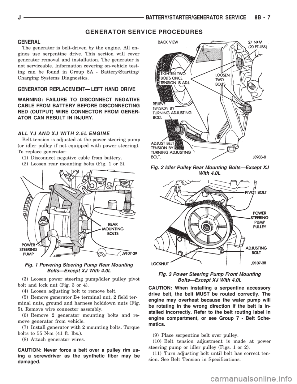
(2) Loosen rear mounting bolts (Fig. 1 or 2).
(3) Loosen power steering pump/idler pulley pivot
bolt and lock nut (Fig. 3 or 4).
(4) Loosen adjusting bolt to remove belt.
(5) Remove generator B+ terminal nut, 2 field ter-
minal nuts, ground and harness holddown nuts (Fig.
5). Remove wire connector assembly.
(6) Remove 2 generator mounting bolts and re-
move generator from vehicle.
(7) Install generator with 2 mounting bolts. Torque
bolts to 55 Nzm (41 ft. lbs.).
(8) Attach generator wires.
CAUTION: Never force a belt over a pulley rim us-
ing a screwdriver as the synthetic fiber may be
damaged.CAUTION: When installing a serpentine accessory
drive belt, the belt MUST be routed correctly. The
engine may overheat because the water pump will
be rotating in the wrong direction if the belt is in-
stalled incorrectly. Refer to the belt routing label in
engine compartment, or see Group 7 - Belt Sche-
matics.
(9) Place serpentine belt over pulley.
(10) Belt tension adjustment is made at power
steering pump or idler pulley (Figs. 1 or 2).
(11) Turn adjusting bolt until belt has correct ten-
sion. See Belt Tension in Specifications.
Fig. 1 Powering Steering Pump Rear Mounting
BoltsÐExcept XJ With 4.0L
Fig. 2 Idler Pulley Rear Mounting BoltsÐExcept XJ
With 4.0L
Fig. 3 Power Steering Pump Front Mounting
BoltsÐExcept XJ With 4.0L
JBATTERY/STARTER/GENERATOR SERVICE 8B - 7
Page 301 of 1784
(12) Tighten rear mounting bolts, pivot bolt, and
lock nut to 27 Nzm (20 ft. lbs.) torque.
(13) Connect negative cable to battery.
XJ WITH 4.0L ENGINE
Belt tension is adjusted at the power steering
pump.
To replace generator:
(1) Disconnect negative cable from battery.
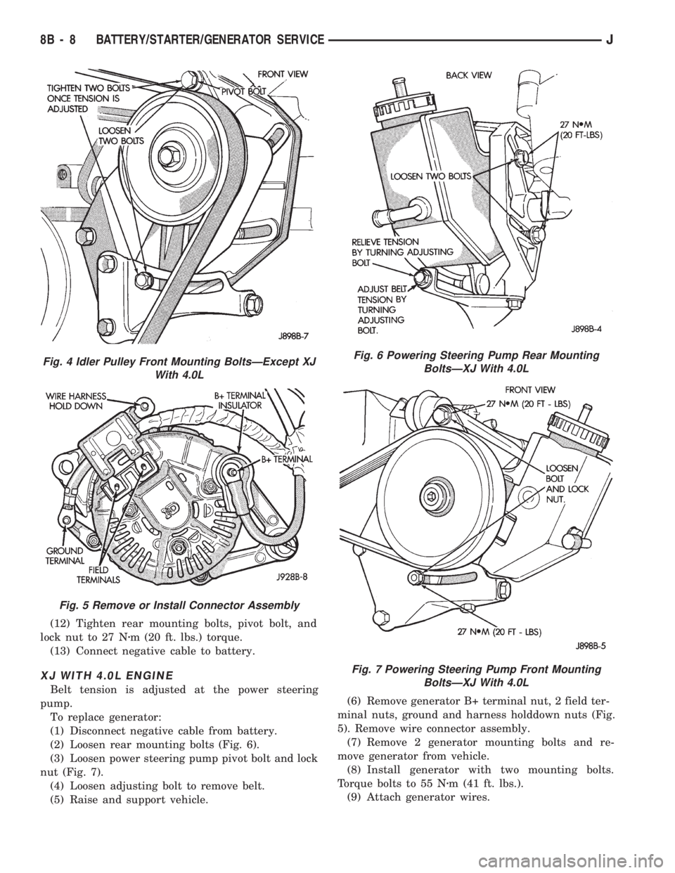
(2) Loosen rear mounting bolts (Fig. 6).
(3) Loosen power steering pump pivot bolt and lock
nut (Fig. 7).
(4) Loosen adjusting bolt to remove belt.
(5) Raise and support vehicle.(6) Remove generator B+ terminal nut, 2 field ter-
minal nuts, ground and harness holddown nuts (Fig.
5). Remove wire connector assembly.
(7) Remove 2 generator mounting bolts and re-
move generator from vehicle.
(8) Install generator with two mounting bolts.
Torque bolts to 55 Nzm (41 ft. lbs.).
(9) Attach generator wires.
Fig. 4 Idler Pulley Front Mounting BoltsÐExcept XJ
With 4.0L
Fig. 5 Remove or Install Connector Assembly
Fig. 6 Powering Steering Pump Rear Mounting
BoltsÐXJ With 4.0L
Fig. 7 Powering Steering Pump Front Mounting
BoltsÐXJ With 4.0L
8B - 8 BATTERY/STARTER/GENERATOR SERVICEJ
Page 302 of 1784
CAUTION: Never force a belt over a pulley rim us-
ing a screwdriver as the synthetic fiber may be
damaged.
CAUTION: When installing a serpentine accessory
drive belt, the belt MUST be routed correctly. The
engine may overheat because the water pump will
be rotating in the wrong direction if the belt is in-
stalled incorrectly. Refer to the belt routing label in
engine compartment, or see Group 7 - Belt Sche-
matics.
(10) Place serpentine belt over pulley.
(11) Belt tension adjustment is made at power
steering pump (Fig. 6).
(12) Turn adjusting bolt until belt has correct ten-
sion. See Belt Tension in Specifications.
(13) Tighten rear mounting bolts, pivot bolt, and
lock nut to 27 Nzm (20 ft. lbs.) torque.
(14) Remove support and lower vehicle.
(15) Connect negative cable to battery.
GENERATOR REPLACEMENTÐRIGHT HAND DRIVE
The generator used on the right hand drive is the
same as used on left hand drive. However, the
mounting and accessory drive belt installation are
different.
WARNING: FAILURE TO DISCONNECT NEGATIVE
CABLE FROM BATTERY BEFORE DISCONNECTING
RED (OUTPUT) WIRE CONNECTOR FROM GENER-
ATOR CAN RESULT IN INJURY.
(1) Remove negative cable from battery.
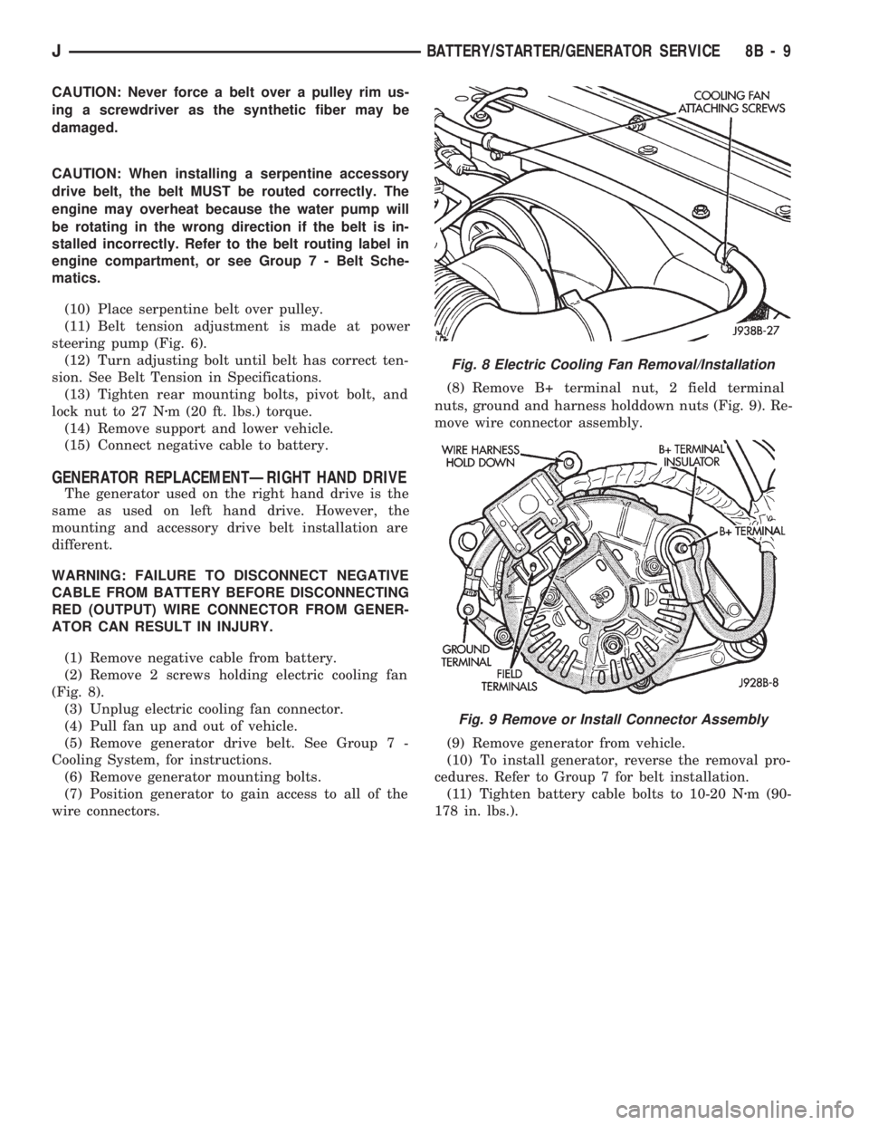
(2) Remove 2 screws holding electric cooling fan
(Fig. 8).
(3) Unplug electric cooling fan connector.
(4) Pull fan up and out of vehicle.
(5) Remove generator drive belt. See Group 7 -
Cooling System, for instructions.
(6) Remove generator mounting bolts.
(7) Position generator to gain access to all of the
wire connectors.(8) Remove B+ terminal nut, 2 field terminal
nuts, ground and harness holddown nuts (Fig. 9). Re-
move wire connector assembly.
(9) Remove generator from vehicle.
(10) To install generator, reverse the removal pro-
cedures. Refer to Group 7 for belt installation.
(11) Tighten battery cable bolts to 10-20 Nzm (90-
178 in. lbs.).
Fig. 8 Electric Cooling Fan Removal/Installation
Fig. 9 Remove or Install Connector Assembly
JBATTERY/STARTER/GENERATOR SERVICE 8B - 9
Page 315 of 1784
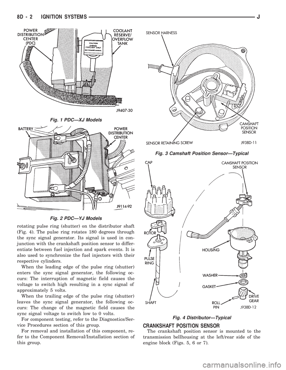
rotating pulse ring (shutter) on the distributor shaft
(Fig. 4). The pulse ring rotates 180 degrees through
the sync signal generator. Its signal is used in con-
junction with the crankshaft position sensor to differ-
entiate between fuel injection and spark events. It is
also used to synchronize the fuel injectors with their
respective cylinders.
When the leading edge of the pulse ring (shutter)
enters the sync signal generator, the following oc-
curs: The interruption of magnetic field causes the
voltage to switch high resulting in a sync signal of
approximately 5 volts.
When the trailing edge of the pulse ring (shutter)
leaves the sync signal generator, the following oc-
curs: The change of the magnetic field causes the
sync signal voltage to switch low to 0 volts.
For component testing, refer to the Diagnostics/Ser-
vice Procedures section of this group.
For removal and installation of this component, re-
fer to the Component Removal/Installation section of
this group.
CRANKSHAFT POSITION SENSOR
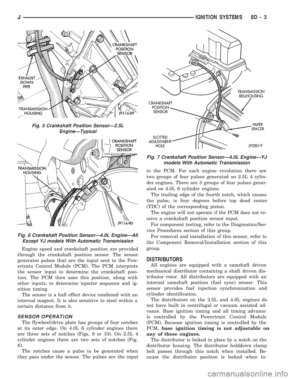
The crankshaft position sensor is mounted to the
transmission bellhousing at the left/rear side of the
engine block (Figs. 5, 6 or 7).
Fig. 1 PDCÐXJ Models
Fig. 2 PDCÐYJ Models
Fig. 3 Camshaft Position SensorÐTypical
Fig. 4 DistributorÐTypical
8D - 2 IGNITION SYSTEMSJ
Page 316 of 1784
Engine speed and crankshaft position are provided
through the crankshaft position sensor. The sensor
generates pulses that are the input sent to the Pow-
ertrain Control Module (PCM). The PCM interprets
the sensor input to determine the crankshaft posi-
tion. The PCM then uses this position, along with
other inputs, to determine injector sequence and ig-
nition timing.
The sensor is a hall effect device combined with an
internal magnet. It is also sensitive to steel within a
certain distance from it.
SENSOR OPERATION
The flywheel/drive plate has groups of four notches
at its outer edge. On 4.0L 6 cylinder engines there
are three sets of notches (Figs. 9 or 10). On 2.5L 4
cylinder engines there are two sets of notches (Fig.
8).
The notches cause a pulse to be generated when
they pass under the sensor. The pulses are the inputto the PCM. For each engine revolution there are
two groups of four pulses generated on 2.5L 4 cylin-
der engines. There are 3 groups of four pulses gener-
ated on 4.0L 6 cylinder engines.
The trailing edge of the fourth notch, which causes
the pulse, is four degrees before top dead center
(TDC) of the corresponding piston.
The engine will not operate if the PCM does not re-
ceive a crankshaft position sensor input.
For component testing, refer to the Diagnostics/Ser-
vice Procedures section of this group.
For removal and installation of this sensor, refer to
the Component Removal/Installation section of this
group.
DISTRIBUTORS
All engines are equipped with a camshaft driven
mechanical distributor containing a shaft driven dis-
tributor rotor. All distributors are equipped with an
internal camshaft position (fuel sync) sensor. This
sensor provides fuel injection synchronization and
cylinder identification.
The distributors on the 2.5L and 4.0L engines do
not have built in centrifugal or vacuum assisted ad-
vance. Base ignition timing and all timing advance
is controlled by the Powertrain Control Module
(PCM). Because ignition timing is controlled by the
PCM,base ignition timing is not adjustable on
any of these engines.
The distributor is locked in place by a notch on the
distributor housing. The distributor holddown clamp
bolt passes through this notch when installed. Be-
cause the distributor position is locked when in-
Fig. 5 Crankshaft Position SensorÐ2.5L
EngineÐTypical
Fig. 6 Crankshaft Position SensorÐ4.0L EngineÐAll
Except YJ models With Automatic Transmission
Fig. 7 Crankshaft Position SensorÐ4.0L EngineÐYJ
models With Automatic Transmission
JIGNITION SYSTEMS 8D - 3