1994 JEEP CHEROKEE lock
[x] Cancel search: lockPage 200 of 1784
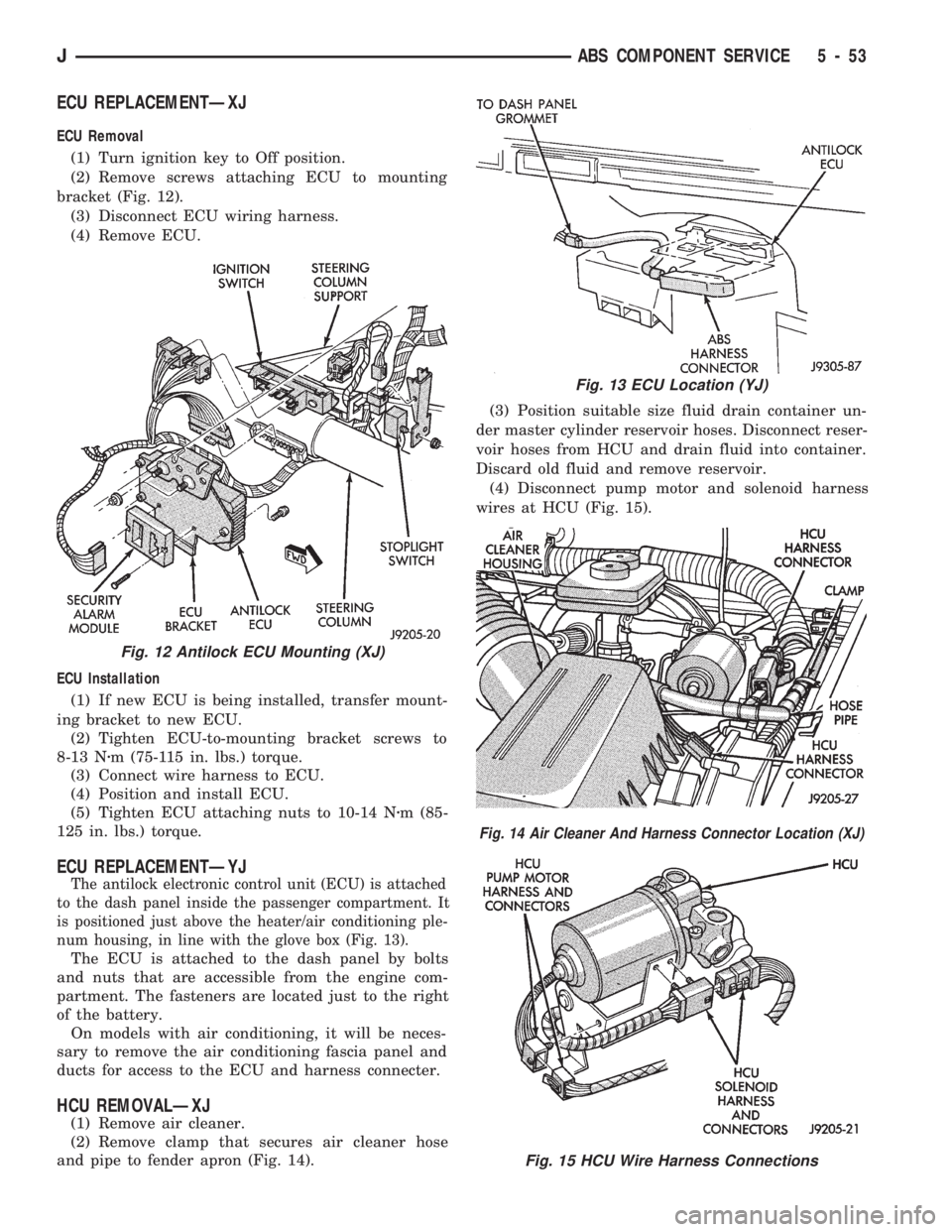
ECU REPLACEMENTÐXJ
ECU Removal
(1) Turn ignition key to Off position.
(2) Remove screws attaching ECU to mounting
bracket (Fig. 12).
(3) Disconnect ECU wiring harness.
(4) Remove ECU.
ECU Installation
(1) If new ECU is being installed, transfer mount-
ing bracket to new ECU.
(2) Tighten ECU-to-mounting bracket screws to
8-13 Nzm (75-115 in. lbs.) torque.
(3) Connect wire harness to ECU.
(4) Position and install ECU.
(5) Tighten ECU attaching nuts to 10-14 Nzm (85-
125 in. lbs.) torque.
ECU REPLACEMENTÐYJ
The antilock electronic control unit (ECU) is attached
to the dash panel inside the passenger compartment. It
is positioned just above the heater/air conditioning ple-
num housing, in line with the glove box (Fig. 13).
The ECU is attached to the dash panel by bolts
and nuts that are accessible from the engine com-
partment. The fasteners are located just to the right
of the battery.
On models with air conditioning, it will be neces-
sary to remove the air conditioning fascia panel and
ducts for access to the ECU and harness connecter.
HCU REMOVALÐXJ
(1) Remove air cleaner.
(2) Remove clamp that secures air cleaner hose
and pipe to fender apron (Fig. 14).(3) Position suitable size fluid drain container un-
der master cylinder reservoir hoses. Disconnect reser-
voir hoses from HCU and drain fluid into container.
Discard old fluid and remove reservoir.
(4) Disconnect pump motor and solenoid harness
wires at HCU (Fig. 15).
Fig. 12 Antilock ECU Mounting (XJ)
Fig. 13 ECU Location (YJ)
Fig. 14 Air Cleaner And Harness Connector Location (XJ)
Fig. 15 HCU Wire Harness Connections
JABS COMPONENT SERVICE 5 - 53
Page 206 of 1784
PARKING BRAKE LEVER REMOVAL (XJ WITH FULL
CONSOLE)
(1) Release parking brakes, if necessary.
(2) Raise vehicle.
(3) Remove adjusting nut from tensioner rod. Then
temporarily secure equalizer to nearby chassis com-
ponent with wire.
(4) Remove nuts attaching lever support plate to
underside of floorpan.
(5) Lower vehicle.
(6) On models with manual transmission, remove
shift knob, boot and bezel.
(7) On models with automatic transmission, re-
move shift handle cap and remove plunger, spring
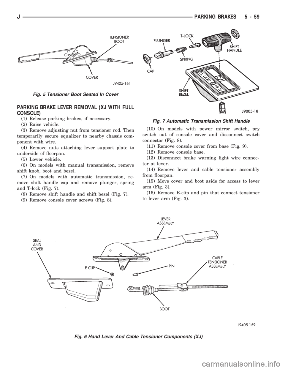
and T-lock (Fig. 7).
(8) Remove shift handle and shift bezel (Fig. 7).
(9) Remove console cover screws (Fig. 8).(10) On models with power mirror switch, pry
switch out of console cover and disconnect switch
connector (Fig. 8).
(11) Remove console cover from base (Fig. 9).
(12) Remove console base.
(13) Disconnect brake warning light wire connec-
tor at lever.
(14) Remove lever and cable tensioner assembly
from floorpan.
(15) Move cover and boot aside for access to lever
arm (Fig. 3).
(16) Remove E-clip and pin that connect tensioner
to lever arm (Fig. 3).
Fig. 6 Hand Lever And Cable Tensioner Components (XJ)
Fig. 5 Tensioner Boot Seated In Cover
Fig. 7 Automatic Transmission Shift Handle
JPARKING BRAKES 5 - 59
Page 210 of 1784
(12) Raise the vehicle.
(13) Install cable-to-frame retaining clip.
(14) Insert cable in equalizer and install equalizer
washer and nuts.
(15) Adjust parking brakes as described in Service
Adjustment section.
PARKING BRAKE REAR CABLE REPLACEMENT (YJ)
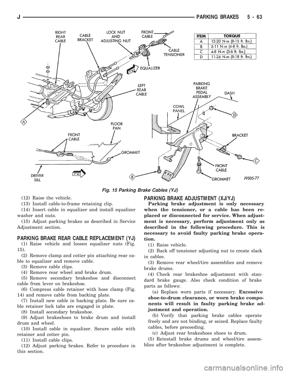
(1) Raise vehicle and loosen equalizer nuts (Fig.
15).
(2) Remove clamp and cotter pin attaching rear ca-
ble to equalizer and remove cable.
(3) Remove cable clips.
(4) Remove rear wheel and brake drum.
(5) Remove secondary brakeshoe and disconnect
cable from lever on brakeshoe.
(6) Compress cable retainer with hose clamp (Fig.
14) and remove cable from backing plate.
(7) Install new cable in backing plate. Be sure ca-
ble retainer lock tabs are engaged in plate.
(8) Install secondary brakeshoe.
(9) Adjust brakeshoes to brake drum and install
drum and wheel.
(10) Install cable in equalizer. Secure cable with
retainer and cotter pin.
(11) Install cable clips.
(12) Adjust parking brakes. Refer to procedure in
this section.
PARKING BRAKE ADJUSTMENT (XJ/YJ)
Parking brake adjustment is only necessary
when the tensioner, or a cable has been re-
placed or disconnected for service. When adjust-
ment is necessary, perform adjustment only as
described in the following procedure. This is
necessary to avoid faulty parking brake opera-
tion.
(1) Raise vehicle.
(2) Back off tensioner adjusting nut to create slack
in cables.
(3) Remove rear wheel/tire assemblies and remove
brake drums.
(4) Check rear brakeshoe adjustment with stan-
dard brake gauge. Also check condition of brake
parts as follows:
(a) Replace worn parts if necessary.Excessive
shoe-to-drum clearance, or worn brake compo-
nents will result in faulty parking brake ad-
justment and operation.
(b) Verify that parking brake cables operate
freely and are not binding, or seized. Replace faulty
cables, before proceeding.
(c) Adjust rear brakeshoes shoes to drum.
(5) Reinstall brake drums and wheel/tire assem-
blies after brakeshoe adjustment is complete.
Fig. 15 Parking Brake Cables (YJ)
JPARKING BRAKES 5 - 63
Page 218 of 1784
CLUTCH DIAGNOSIS
INDEX
page page
Clutch Problem Causes..................... 3
General Diagnosis Information................ 3Inspection and Diagnosis Charts.............. 4
GENERAL DIAGNOSIS INFORMATION
Unless the cause of a clutch problem is obvious, ac-
curate problem diagnosis will usually require a road
test to confirm a problem. Component inspection will
then be required to determine the actual problem
cause.
During a road test, drive the vehicle at normal
speeds. Shift the transmission through all gear
ranges and observe clutch action. If chatter, grab,
slip, or improper release is experienced, remove and
inspect the clutch components. However, if the prob-
lem is noise or hard shifting, further diagnosis may
be needed as the transmission or another driveline
component may be at fault. Careful observation dur-
ing the test will help narrow the problem area.
CLUTCH PROBLEM CAUSES
CONTAMINATION
Fluid contamination is a frequent cause of clutch
malfunctions. Oil, water, or clutch fluid on the clutch
contact surfaces will cause faulty operation. The
usual result is chatter, slip and grab.
During inspection, note if any components are con-
taminated with oil, hydraulic fluid, or water/road
splash.
Oil contamination indicates a leak at either the
rear main seal or transmission input shaft. Oil leak-
age produces a residue of oil on the housing interior
and on the clutch cover and flywheel. Heat buildup
caused by slippage between the cover, disc and fly-
wheel, can sometimes bake the oil residue onto the
components. The glaze-like residue ranges in color
from amber to black.
Road splash contamination means dirt/water is en-
tering the clutch housing due to loose bolts, housing
cracks, or through hydraulic line openings. Driving
through deep water puddles can force water/road
splash into the housing through such openings.
Clutch fluid leaks are from loose or damaged slave
cylinder fluid lines and connecting fittings. However,
clutch fluid leaks will usually be noted and corrected
before severe contamination occurs.
CLUTCH MISALIGNMENT
Clutch components must be in proper alignment
with the crankshaft and transmission input shaft.Misalignment caused by excessive runout or warpage
of any clutch component will cause grab, chatter and
improper clutch release.
Flywheel Runout
Check flywheel runout whenever misalignment is
suspected. Flywheel runout should not exceed 0.08
mm (0.003 in.). Measure runout at the outer edge of
the flywheel face with a dial indicator. Mount the in-
dicator on a stud installed in place of one of the fly-
wheel bolts.
Common causes of runout are:
²heat warpage
²improper machining
²incorrect bolt tightening
²improper seating on crankshaft flange shoulder
²foreign material on crankshaft flange
Flywheel machining is not recommended. The fly-
wheel clutch surface is machined to a unique contour
and machining will negate this feature. However,
minor flywheel scoring can be cleaned up by hand
with 180 grit emery, or with surface grinding equip-
ment. Remove only enough material to reduce scor-
ing (approximately 0.001 - 0.003 in.). Heavy stock
removal isnot recommended.Replace the flywheel
if scoring is severe and deeper than 0.076 mm (0.003
in.). Excessive stock removal can result in flywheel
cracking or warpage after installation; it can also
weaken the flywheel and interfere with proper clutch
release.
Clean the crankshaft flange before mounting the
flywheel. Dirt and grease on the flange surface may
cock the flywheel causing excessive runout. Use new
bolts when remounting a flywheel and secure the
bolts with Mopar Lock And Seal. Tighten flywheel
bolts to specified torque only. Overtightening can dis-
tort the flywheel hub causing runout.
Clutch Cover And Disc Runout
Check the clutch disc before installation. Axial
(face) runout of anewdisc should not exceed 0.50
mm (0.020 in.). Measure runout about 6 mm (1/4 in.)
from the outer edge of the disc facing. Obtain an-
other disc if runout is excessive.
Check condition of the clutch before installation. A
warped cover or diaphragm spring will cause grab
and incomplete release or engagement. Be careful
JCLUTCH DIAGNOSIS 6 - 3
Page 231 of 1784
Check flywheel runout if misalignment is sus-
pected. Runout should not exceed 0.08 mm (0.003
in.). Measure runout at the outer edge of the fly-
wheel face with a dial indicator. Mount the dial indi-
cator on a stud installed in place of one of the
flywheel attaching bolts.
Clean the crankshaft flange before mounting the
flywheel. Dirt and grease on the flange surface may
cock the flywheel causing excessive runout.
Check condition of the flywheel hub and attaching
bolts. Replace the flywheel if the hub exhibits cracks
in the area of the attaching bolt holes.
Install new attaching bolts whenever the flywheel
is replaced and use Mopar Lock N' Seal, or Loctite
242 on the replacement bolt threads.
Recommended flywheel bolt torques are:
²142 Nzm (105 ft. lbs.) for 6-cylinder flywheels
²68 Nzm (50 ft. lbs.) plus an additional turn of 60É
for 4-cylinder flywheels
Inspect the teeth on the starter ring gear.If the
teeth are worn or damaged, the flywheel should
be replaced as an assembly. This is the recom-
mended and preferred method of repair.
In cases where a new flywheel is not readily avail-
able, a replacement ring gear can be installed. How-
ever, the following precautions must be observed to
avoid damaging the flywheel and replacement gear.
(a) Mark position of the old gear for alignment
reference on the flywheel. Use a scriber for this
purpose.
(b) Wear protective goggles or approved safety
glasses. Also wear heat resistent gloves when han-
dling a heated ring gear.
(c) Remove the old gear by cutting most of the
way through it (at one point) with an abrasive cut-
off wheel. Then complete removal with a cold chisel
or punch.(d) The ring gear is a shrink fit on the flywheel.
This means the gear must be expanded by heating
in order to install it.The method of heating and
expanding the gear is extremely important.
Every surface of the gear must be heated at the
same time to produce uniform expansion. An oven
or similar enclosed heating device must be used.
Temperature required for uniform expansion is ap-
proximately 375É F.
CAUTION: Do not use an oxy/acetylene torch to re-
move the old gear, or to heat and expand a new
gear. The high temperature of the torch flame can
cause localized heating that will damage the fly-
wheel. In addition, using the torch to heat a replace-
ment gear will cause uneven heating and
expansion. The torch flame can also anneal the
gear teeth resulting in rapid wear and damage after
installation.
(e) The heated gear must be installed evenly to
avoid misalignment or distortion. A shop press and
suitable press plates should be used to install the
gear if at all possible.
(f) Be sure to wear eye and hand protection.
Heat resistent gloves and safety goggles are needed
for personal safety. Also use metal tongs, vise grips,
or similar tools to position the gear as necessary
for installation.
(g) Allow the flywheel and ring gear to cool down
before installation. Set the assembly on a work-
bench and let it cool in normal shop air.
CAUTION: Do not use water, or compressed air to
cool the flywheel. The rapid cooling produced by
water or compressed air can distort, or crack the
gear and flywheel.
6 - 16 CLUTCH SERVICEJ
Page 234 of 1784
COOLING SYSTEM
CONTENTS
page page
DIAGNOSIS............................. 4
ENGINE ACCESSORY DRIVE BELTS........ 31
ENGINE BLOCK HEATER................. 37GENERAL INFORMATION.................. 1
SERVICE PROCEDURES................... 9
SPECIFICATIONS....................... 38
GENERAL INFORMATION
Throughout this group, references are made to par-
ticular vehicle models by alphabetical designation
(XJ or YJ) or by the particular vehicle nameplate. A
chart showing a breakdown of alphabetical designa-
tions is included in the Introduction section at the
beginning of this manual.
COOLING SYSTEM
The cooling system regulates engine operating tem-
perature. It allows the engine to reach normal oper-
ating temperature as quickly as possible, maintains
normal operating temperature and prevents over-
heating.
The cooling system also provides a means of heat-
ing the passenger compartment and cooling the auto-
matic transmission fluid (if equipped). The cooling
system is pressurized and uses a centrifugal water
pump to circulate coolant throughout the system.
An optional factory installed heavy duty cooling
package is available on most models. The package
consists of a radiator that has an increased numberof cooling fins. XJ models equipped with a 4.0L 6 cyl-
inder engine and heavy duty cooling and/or air con-
ditioning also have an auxiliary electric cooling fan.
COOLING SYSTEM COMPONENTS
The cooling system consists of:
²A radiator
²Cooling fan (mechanical and/or electrical)
²Thermal viscous fan drive
²Fan shroud
²Radiator pressure cap
²Thermostat
²Coolant reserve/overflow system
²Transmission oil cooler (if equipped with an auto-
matic transmission)
²Coolant
²Water pump
²Hoses and hose clamps
SYSTEM COOLANT ROUTING
For cooling system flow routings, refer to Figs. 1, 2,
3or4.
JCOOLING SYSTEM 7 - 1
Page 242 of 1784
SERVICE PROCEDURES
INDEX
page page
Coolant................................ 15
Coolant Reserve/Overflow System............ 19
Cooling System Cleaning/Reverse Flushing..... 17
Cooling System Fans..................... 26
Cooling System Hoses.................... 26
Draining Cooling System................... 16
Radiator Pressure Cap.................... 20
Radiators............................... 22Refilling Cooling System................... 17
Testing Cooling System for Leaks............ 18
Thermostat............................. 13
Transmission Oil Coolers................... 29
Water Pump Tests........................ 9
Water PumpsÐGeneral Information............ 9
Water PumpsÐRemoval/Installation........... 10
WATER PUMPSÐGENERAL INFORMATION
A centrifugal water pump circulates coolant
through the water jackets, passages, intake manifold,
radiator core, cooling system hoses and heater core.
The pump is driven from the engine crankshaft by a
drive belt on all engines.
The water pump impeller is pressed onto the rear
of a shaft that rotates in bearings pressed into the
housing. The housing has a small hole to allow seep-
age to escape. The water pump seals are lubricated
by the antifreeze in the coolant mixture. No addi-
tional lubrication is necessary.
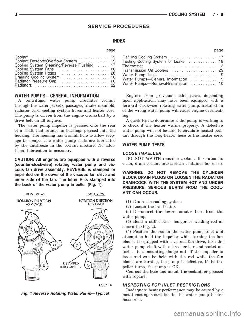
CAUTION: All engines are equipped with a reverse
(counter-clockwise) rotating water pump and vis-
cous fan drive assembly. REVERSE is stamped or
imprinted on the cover of the viscous fan drive and
inner side of the fan. The letter R is stamped into
the back of the water pump impeller (Fig. 1).Engines from previous model years, depending
upon application, may have been equipped with a
forward (clockwise) rotating water pump. Installation
of the wrong water pump will cause engine overheat-
ing.
A quick test to determine if the pump is working is
to check if the heater warms properly. A defective
water pump will not be able to circulate heated cool-
ant through the long heater hose to the heater core.
WATER PUMP TESTS
LOOSE IMPELLER
DO NOT WASTE reusable coolant. If solution is
clean, drain coolant into a clean container for reuse.
WARNING: DO NOT REMOVE THE CYLINDER
BLOCK DRAIN PLUGS OR LOOSEN THE RADIATOR
DRAINCOCK WITH THE SYSTEM HOT AND UNDER
PRESSURE. SERIOUS BURNS FROM THE COOL-
ANT CAN OCCUR.
(1) Drain the cooling system.
(2) Loosen the fan belt(s).
(3) Disconnect the lower radiator hose from the
water pump.
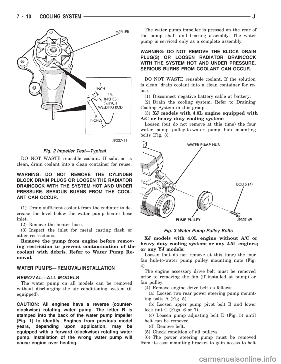
(4) Bend a stiff clothes hanger or welding rod as
shown in (Fig. 2).
(5) Position the rod in the water pump inlet and
attempt to hold the impeller while turning the fan
blades. If equipped with a viscous fan drive, turn the
water pump shaft with a breaker bar and socket at-
tached to a mounting flange nut. If the impeller is
loose and can be held with the rod while the fan
blades are turning, the pump is defective. If the im-
peller turns, the pump is OK.
Connect the hose and install the coolant, or proceed
with repairs.
INSPECTING FOR INLET RESTRICTIONS
Inadequate heater performance may be caused by a
metal casting restriction in the water pump heater
hose inlet.Fig. 1 Reverse Rotating Water PumpÐTypical
JCOOLING SYSTEM 7 - 9
Page 243 of 1784
DO NOT WASTE reusable coolant. If solution is
clean, drain coolant into a clean container for reuse.
WARNING: DO NOT REMOVE THE CYLINDER
BLOCK DRAIN PLUGS OR LOOSEN THE RADIATOR
DRAINCOCK WITH THE SYSTEM HOT AND UNDER
PRESSURE. SERIOUS BURNS FROM THE COOL-
ANT CAN OCCUR.
(1) Drain sufficient coolant from the radiator to de-
crease the level below the water pump heater hose
inlet.
(2) Remove the heater hose.
(3) Inspect the inlet for metal casting flash or
other restrictions.
Remove the pump from engine before remov-
ing restriction to prevent contamination of the
coolant with debris. Refer to Water Pump Re-
moval.
WATER PUMPSÐREMOVAL/INSTALLATION
REMOVALÐALL MODELS
The water pump on all models can be removed
without discharging the air conditioning system (if
equipped).
CAUTION: All engines have a reverse (counter-
clockwise) rotating water pump. The letter R is
stamped into the back of the water pump impeller
(Fig. 1) to identify. Engines from previous model
years, depending upon application, may be
equipped with a forward (clockwise) rotating water
pump. Installation of the wrong water pump will
cause engine over heating.The water pump impeller is pressed on the rear of
the pump shaft and bearing assembly. The water
pump is serviced only as a complete assembly.
WARNING: DO NOT REMOVE THE BLOCK DRAIN
PLUG(S) OR LOOSEN RADIATOR DRAINCOCK
WITH THE SYSTEM HOT AND UNDER PRESSURE.
SERIOUS BURNS FROM COOLANT CAN OCCUR.
DO NOT WASTE reusable coolant. If the solution
is clean, drain coolant into a clean container for re-
use.
(1) Disconnect negative battery cable at battery.
(2) Drain the cooling system. Refer to Draining
Cooling System in this group.
(3)XJ models with 4.0L engine equipped with
A/C or heavy duty cooling system:
Loosen (but do not remove at this time) the four
water pump pulley-to-water pump hub mounting
bolts (Fig. 3).
XJ models with 4.0L engine without A/C or
heavy duty cooling system; or any 2.5L engines;
or any YJ models:
Loosen (but do not remove at this time) the four
fan hub-to-water pump pulley mounting nuts (Fig.
4).
The engine accessory drive belt must be removed
prior to removing the fan (if installed at pump) or
fan pulley.
(4) Remove engine drive belt as follows:
(a) Loosen two rear power steering pump mount-
ing bolts A (Fig. 5).
(b) Loosen upper pump pivot bolt B and lower
lock nut C (Figs. 6 or 7).
(c) Loosen pump adjusting bolt D (Fig. 5) until
belt can be removed.
(d) Remove belt.
(5) Check condition of all pulleys.
(6) The power steering pump must be removed
from its cast mounting bracket to gain access to bolt
Fig. 2 Impeller TestÐTypical
Fig. 3 Water Pump Pulley Bolts
7 - 10 COOLING SYSTEMJ