1994 JEEP CHEROKEE lock
[x] Cancel search: lockPage 160 of 1784
BRAKE BLEEDINGÐBRAKE FLUID AND LEVELÐBRAKELINES AND HOSES
INDEX
page page
Brake BleedingÐXJ/YJ with ABS Brakes....... 14
Brake BleedingÐXJ/YJ with Standard Brakes . . . 13
Brake Fluid Contamination.................. 13
Brake Fluid Level........................ 13Brakeline Charts......................... 15
Brakelines and Hoses..................... 15
Combination Valve....................... 15
Recommended Brake Fluid................. 13
RECOMMENDED BRAKE FLUID
The only brake fluid recommended for Jeep vehi-
cles with standard or antilock brakes, is Mopar brake
fluid, or an equivalent fluid meeting SAE J1703 and
DOT 3 standards.
Use new brake fluid only to top off the master
cylinder or refill the system. Never use re-
claimed fluid, fluid not meeting the SAE/DOT
standards or fluid from an unsealed container.
Do not use fluid from any container that has
been left open for any length of time. Fluid in
open containers can absorb moisture.
BRAKE FLUID LEVEL
Always clean the master cylinder and cover before
checking fluid level. If not cleaned, dirt from the
cover could enter the fluid. Also check the cover seal
and replace it if torn or distorted.
Correct fluid level is to within 6 mm (1/4 in.) of the
reservoir rim, or to the fill mark on models with a
plastic reservoir. Refer to the Antilock Brake section
for fluid levels on models equipped with ABS brakes.
BRAKE FLUID CONTAMINATION
Oil in the fluid will cause brake system rubber
seals to soften and swell. The seals may also become
porous and begin to deteriorate.
If fluid contamination is suspected, drain off a sam-
ple from the master cylinder. A suction gun or simi-
lar device can be used for this purpose.
Empty the drained fluid into a glass container.
Contaminants in the fluid will cause the fluid to sep-
arate into distinct layers. If contamination has oc-
curred, the system rubber seals, hoses and cups must
be replaced and the system thoroughly flushed with
clean brake fluid.
BRAKE BLEEDINGÐXJ/YJ WITH STANDARD
BRAKES
Use Mopar DOT 3 brake fluid, or an equivalent
meeting SAE/DOT standards J1703-F and DOT 3, to
fill and bleed the system.
On standard brake models, bleeding can be per-
formed either manually or with pressure equipment.
However, if pressure equipment is used, it will be
necessary to hold the front brake metering valveopen in order to bleed the front brakes. The valve
can be held open with a tension clip tool or by hand.
It will also be necessary that a suitable size pressure
tank hose adapter be available for use on the master
cylinder.
MANUAL BLEEDING PROCEDURE
(1) If master cylinder has been overhauled or a
new cylinder will be installed, bleed cylinder on
bench before installation. This shortens time needed
to bleed system and ensures proper cylinder opera-
tion.
(2) Wipe master cylinder reservoir and cap clean
with shop towels.
(3) Remove cover and fill master cylinder reservoir
with Mopar, or equivalent DOT 3 brake fluid.
(4) Open all caliper and wheel cylinder bleed
screws.
(5) Close bleed screws after fluid begins flowing
from each bleed screw.
(6) Top off master cylinder reservoir again.
(7) Use following bleed sequence:
²master cylinder
²right rear
²left rear
²right front
²left front
(8) Observe following brake bleeding precautions:
²Do not pump brake pedal at any time while bleed-
ing. Air in system will be compressed into small bub-
bles that are distributed throughout hydraulic
system. This will make a second and third bleeding
operation necessary.
²Bleed only one wheel brake unit at a time and use
a bleed hose to bleed each wheel brake unit (Fig. 7).
²Attach one end of bleed hose to bleed screw and in-
sert opposite end in glass container partially filled
with brake fluid (Fig. 7). Glass container makes it
easier to see air bubbles as they exit the bleed hose.
²Be sure end of bleed hose is immersed in fluid. Im-
mersing hose end in fluid prevents air from being
drawn back into cylinder and brakeline.
(9) Bleed master cylinder first. Have helper oper-
ate brake pedal while bleeding each master cylinder
fluid outlet line.
JBRAKES 5 - 13
Page 167 of 1784
STANDARD MASTER CYLINDER
INDEX
page page
General Service Information................ 20
Master Cylinder Installation................. 20Master Cylinder Overhaul.................. 20
Master Cylinder Removal.................. 20
GENERAL SERVICE INFORMATION
The service information in this section covers the
standard (non-ABS) master cylinder only. The center
feed master cylinder used with the ABS system is
covered in the antilock brake component service sec-
tion.
MASTER CYLINDER REMOVAL
(1) Disconnect brake lines at master cylinder.
(2) Remove cylinder mounting nuts and remove
master cylinder.
(3) Remove cylinder cover and drain fluid.
MASTER CYLINDER INSTALLATION
(1) Bleed master cylinder on bench before installa-
tion. Refer to overhaul assembly procedure in this
section for bleeding method.
(2) Install cylinder on brake booster studs and in-
stall cylinder attaching nuts. Tighten nuts to 21 NIm
(15 ft. lbs.).
(3) Connect brakelines to cylinder.
(4) Fill and bleed brake system.
MASTER CYLINDER OVERHAUL
CYLINDER DISASSEMBLY
(1) Remove cylinder cover and drain fluid.
(2) Examine cylinder cover seal. Discard seal if
torn or distorted.
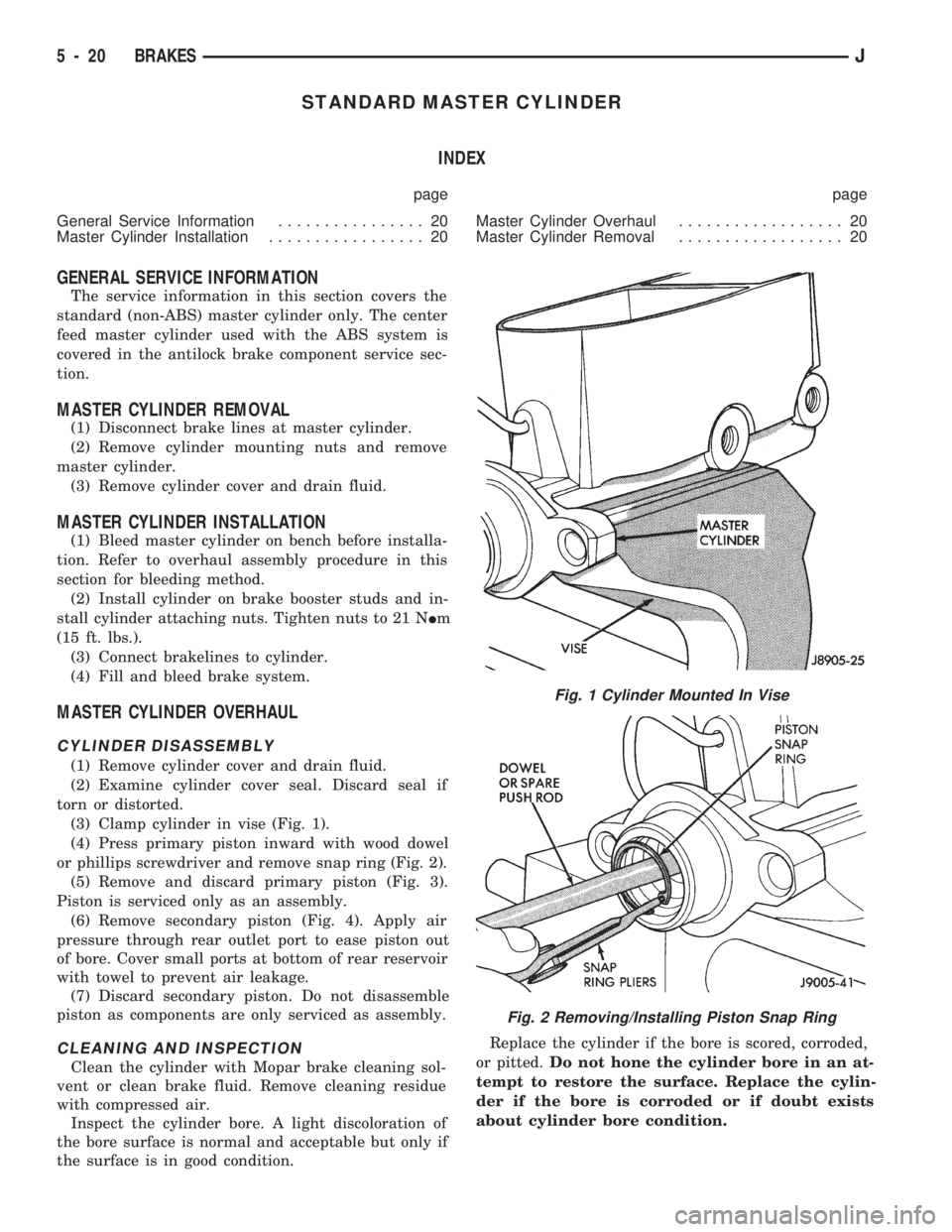
(3) Clamp cylinder in vise (Fig. 1).
(4) Press primary piston inward with wood dowel
or phillips screwdriver and remove snap ring (Fig. 2).
(5) Remove and discard primary piston (Fig. 3).
Piston is serviced only as an assembly.
(6) Remove secondary piston (Fig. 4). Apply air
pressure through rear outlet port to ease piston out
of bore. Cover small ports at bottom of rear reservoir
with towel to prevent air leakage.
(7) Discard secondary piston. Do not disassemble
piston as components are only serviced as assembly.
CLEANING AND INSPECTION
Clean the cylinder with Mopar brake cleaning sol-
vent or clean brake fluid. Remove cleaning residue
with compressed air.
Inspect the cylinder bore. A light discoloration of
the bore surface is normal and acceptable but only if
the surface is in good condition.Replace the cylinder if the bore is scored, corroded,
or pitted.Do not hone the cylinder bore in an at-
tempt to restore the surface. Replace the cylin-
der if the bore is corroded or if doubt exists
about cylinder bore condition.
Fig. 1 Cylinder Mounted In Vise
Fig. 2 Removing/Installing Piston Snap Ring
5 - 20 BRAKESJ
Page 170 of 1784
(7) Carefully move master cylinder aside and re-
move booster.
POWER BRAKE BOOSTER INSTALLATION
(1) Install check valve and grommet in booster.
Also install spacer on booster, if equipped.
(2) Position booster on dash panel and install
booster mounting bolts/nuts.
(3) Working inside vehicle, install nuts on booster
mounting studs.
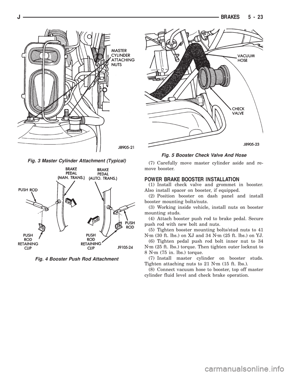
(4) Attach booster push rod to brake pedal. Secure
push rod with new bolt and nuts.
(5) Tighten booster mounting bolts/stud nuts to 41
Nzm (30 ft. lbs.) on XJ and 34 Nzm (25 ft. lbs.) on YJ.
(6) Tighten pedal push rod bolt inner nut to 34
Nzm (25 ft. lbs.) torque. Then tighten outer locknut to
8Nzm (75 in. lbs.) torque.
(7) Install master cylinder on booster studs.
Tighten attaching nuts to 21 Nzm (15 ft. lbs.).
(8) Connect vacuum hose to booster, top off master
cylinder fluid level and check brake operation.
Fig. 3 Master Cylinder Attachment (Typical)
Fig. 4 Booster Push Rod Attachment
Fig. 5 Booster Check Valve And Hose
JBRAKES 5 - 23
Page 183 of 1784
(2) Verify that left/right automatic adjuster lever
and cable are properly connected.
(3) Insert brake gauge in drum. Expand gauge un-
til gauge inner legs contact drum braking surface.
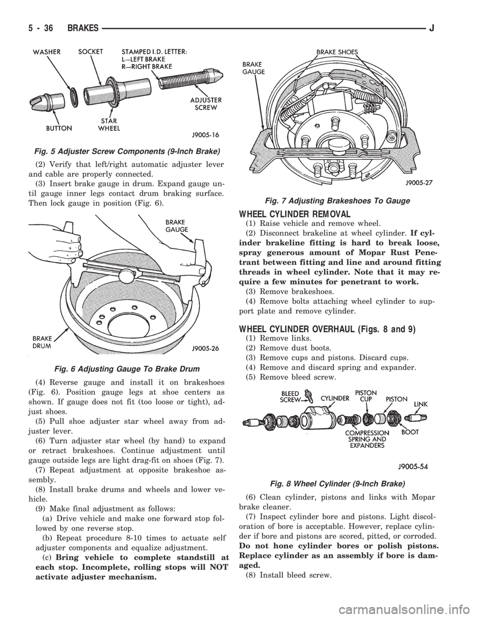
Then lock gauge in position (Fig. 6).
(4) Reverse gauge and install it on brakeshoes
(Fig. 6). Position gauge legs at shoe centers as
shown. If gauge does not fit (too loose or tight), ad-
just shoes.
(5) Pull shoe adjuster star wheel away from ad-
juster lever.
(6) Turn adjuster star wheel (by hand) to expand
or retract brakeshoes. Continue adjustment until
gauge outside legs are light drag-fit on shoes (Fig. 7).
(7) Repeat adjustment at opposite brakeshoe as-
sembly.
(8) Install brake drums and wheels and lower ve-
hicle.
(9) Make final adjustment as follows:
(a) Drive vehicle and make one forward stop fol-
lowed by one reverse stop.
(b) Repeat procedure 8-10 times to actuate self
adjuster components and equalize adjustment.
(c)Bring vehicle to complete standstill at
each stop. Incomplete, rolling stops will NOT
activate adjuster mechanism.
WHEEL CYLINDER REMOVAL
(1) Raise vehicle and remove wheel.
(2) Disconnect brakeline at wheel cylinder.If cyl-
inder brakeline fitting is hard to break loose,
spray generous amount of Mopar Rust Pene-
trant between fitting and line and around fitting
threads in wheel cylinder. Note that it may re-
quire a few minutes for penetrant to work.
(3) Remove brakeshoes.
(4) Remove bolts attaching wheel cylinder to sup-
port plate and remove cylinder.
WHEEL CYLINDER OVERHAUL (Figs. 8 and 9)
(1) Remove links.
(2) Remove dust boots.
(3) Remove cups and pistons. Discard cups.
(4) Remove and discard spring and expander.
(5) Remove bleed screw.
(6) Clean cylinder, pistons and links with Mopar
brake cleaner.
(7) Inspect cylinder bore and pistons. Light discol-
oration of bore is acceptable. However, replace cylin-
der if bore and pistons are scored, pitted, or corroded.
Do not hone cylinder bores or polish pistons.
Replace cylinder as an assembly if bore is dam-
aged.
(8) Install bleed screw.
Fig. 5 Adjuster Screw Components (9-Inch Brake)
Fig. 6 Adjusting Gauge To Brake Drum
Fig. 7 Adjusting Brakeshoes To Gauge
Fig. 8 Wheel Cylinder (9-Inch Brake)
5 - 36 BRAKESJ
Page 184 of 1784
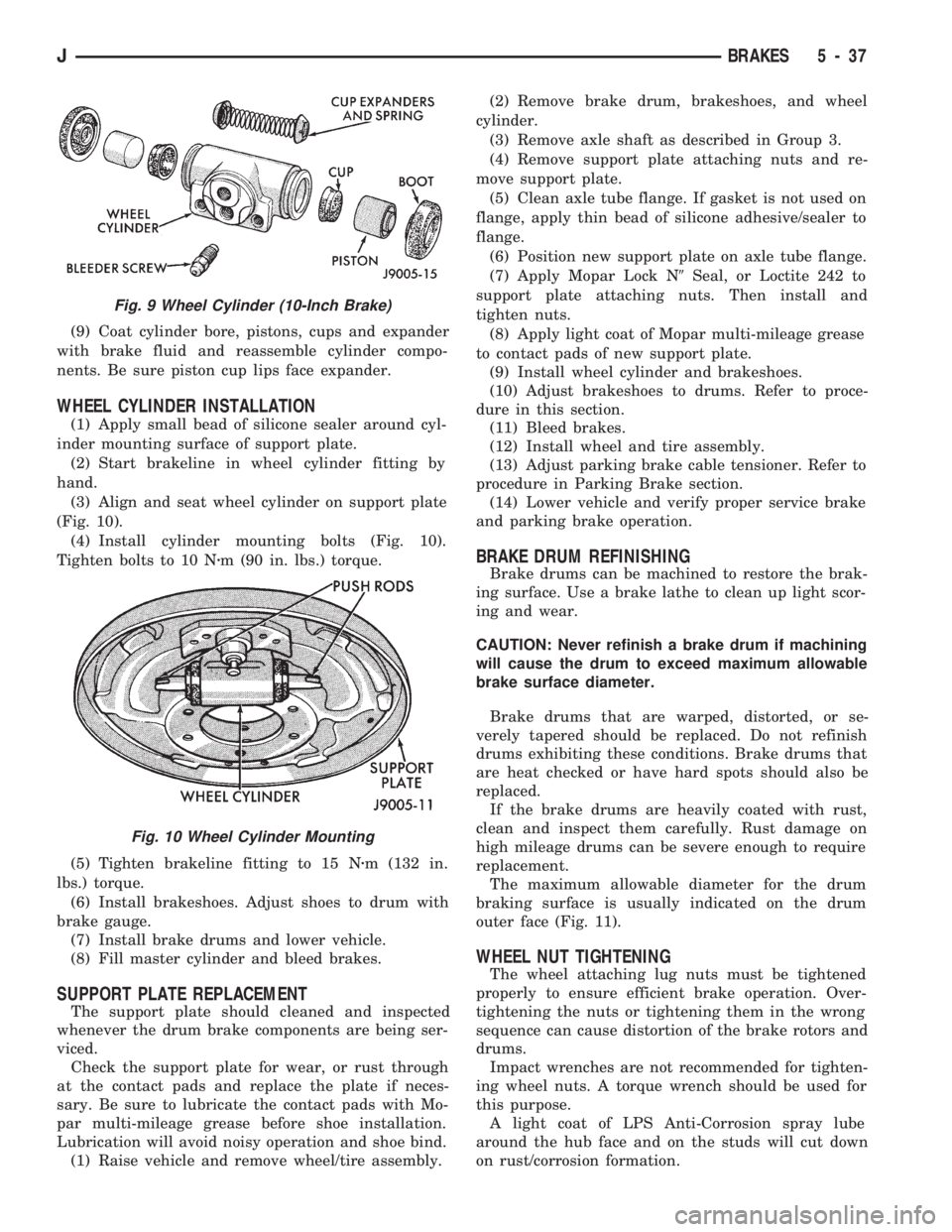
(9) Coat cylinder bore, pistons, cups and expander
with brake fluid and reassemble cylinder compo-
nents. Be sure piston cup lips face expander.
WHEEL CYLINDER INSTALLATION
(1) Apply small bead of silicone sealer around cyl-
inder mounting surface of support plate.
(2) Start brakeline in wheel cylinder fitting by
hand.
(3) Align and seat wheel cylinder on support plate
(Fig. 10).
(4) Install cylinder mounting bolts (Fig. 10).
Tighten bolts to 10 Nzm (90 in. lbs.) torque.
(5) Tighten brakeline fitting to 15 Nzm (132 in.
lbs.) torque.
(6) Install brakeshoes. Adjust shoes to drum with
brake gauge.
(7) Install brake drums and lower vehicle.
(8) Fill master cylinder and bleed brakes.
SUPPORT PLATE REPLACEMENT
The support plate should cleaned and inspected
whenever the drum brake components are being ser-
viced.
Check the support plate for wear, or rust through
at the contact pads and replace the plate if neces-
sary. Be sure to lubricate the contact pads with Mo-
par multi-mileage grease before shoe installation.
Lubrication will avoid noisy operation and shoe bind.
(1) Raise vehicle and remove wheel/tire assembly.(2) Remove brake drum, brakeshoes, and wheel
cylinder.
(3) Remove axle shaft as described in Group 3.
(4) Remove support plate attaching nuts and re-
move support plate.
(5) Clean axle tube flange. If gasket is not used on
flange, apply thin bead of silicone adhesive/sealer to
flange.
(6) Position new support plate on axle tube flange.
(7) Apply Mopar Lock N9Seal, or Loctite 242 to
support plate attaching nuts. Then install and
tighten nuts.
(8) Apply light coat of Mopar multi-mileage grease
to contact pads of new support plate.
(9) Install wheel cylinder and brakeshoes.
(10) Adjust brakeshoes to drums. Refer to proce-
dure in this section.
(11) Bleed brakes.
(12) Install wheel and tire assembly.
(13) Adjust parking brake cable tensioner. Refer to
procedure in Parking Brake section.
(14) Lower vehicle and verify proper service brake
and parking brake operation.
BRAKE DRUM REFINISHING
Brake drums can be machined to restore the brak-
ing surface. Use a brake lathe to clean up light scor-
ing and wear.
CAUTION: Never refinish a brake drum if machining
will cause the drum to exceed maximum allowable
brake surface diameter.
Brake drums that are warped, distorted, or se-
verely tapered should be replaced. Do not refinish
drums exhibiting these conditions. Brake drums that
are heat checked or have hard spots should also be
replaced.
If the brake drums are heavily coated with rust,
clean and inspect them carefully. Rust damage on
high mileage drums can be severe enough to require
replacement.
The maximum allowable diameter for the drum
braking surface is usually indicated on the drum
outer face (Fig. 11).
WHEEL NUT TIGHTENING
The wheel attaching lug nuts must be tightened
properly to ensure efficient brake operation. Over-
tightening the nuts or tightening them in the wrong
sequence can cause distortion of the brake rotors and
drums.
Impact wrenches are not recommended for tighten-
ing wheel nuts. A torque wrench should be used for
this purpose.
A light coat of LPS Anti-Corrosion spray lube
around the hub face and on the studs will cut down
on rust/corrosion formation.
Fig. 9 Wheel Cylinder (10-Inch Brake)
Fig. 10 Wheel Cylinder Mounting
JBRAKES 5 - 37
Page 186 of 1784
ABS SYSTEM OPERATION
INDEX
page page
Acceleration Switch....................... 41
Combination Valve....................... 42
Electronic Control Unit (ECU)............... 41
General Information....................... 39
Hydraulic Control Unit (HCU)................ 39
Ignition Switch........................... 42Master Cylinder.......................... 40
Pedal Travel Sensor...................... 41
Power Brake Booster..................... 40
System Relays.......................... 42
System Warning Lights.................... 42
Wheel Speed Sensors..................... 41
GENERAL INFORMATION
The Jeep antilock brake system (ABS) is an elec-
tronically operated, all-wheel brake control system.
Major components include the master cylinder, vac-
uum power brake booster, ECU, hydraulic control
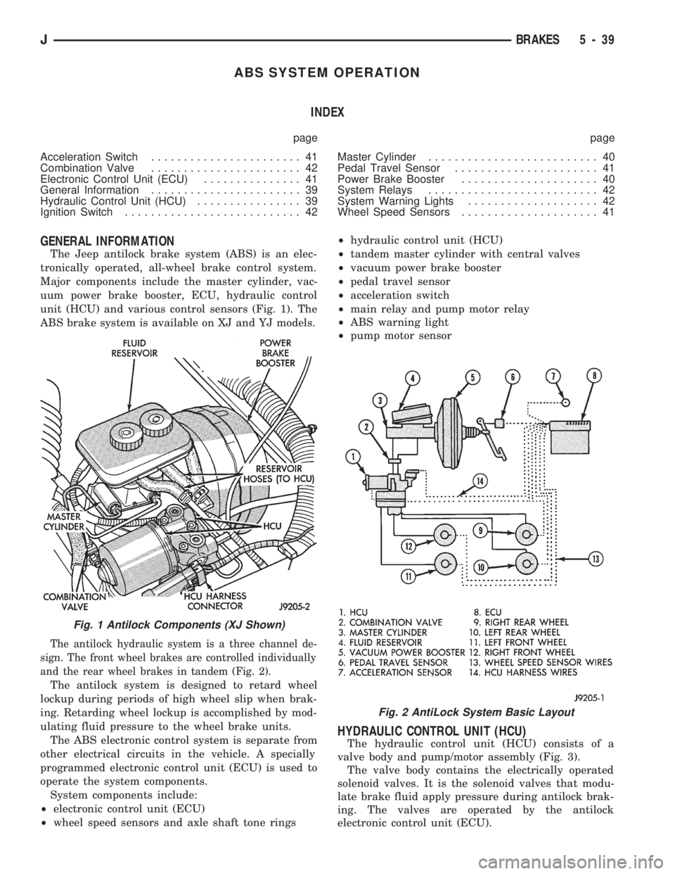
unit (HCU) and various control sensors (Fig. 1). The
ABS brake system is available on XJ and YJ models.
The antilock hydraulic system is a three channel de-
sign. The front wheel brakes are controlled individually
and the rear wheel brakes in tandem (Fig. 2).
The antilock system is designed to retard wheel
lockup during periods of high wheel slip when brak-
ing. Retarding wheel lockup is accomplished by mod-
ulating fluid pressure to the wheel brake units.
The ABS electronic control system is separate from
other electrical circuits in the vehicle. A specially
programmed electronic control unit (ECU) is used to
operate the system components.
System components include:
²electronic control unit (ECU)
²wheel speed sensors and axle shaft tone rings²hydraulic control unit (HCU)
²tandem master cylinder with central valves
²vacuum power brake booster
²pedal travel sensor
²acceleration switch
²main relay and pump motor relay
²ABS warning light
²pump motor sensor
HYDRAULIC CONTROL UNIT (HCU)
The hydraulic control unit (HCU) consists of a
valve body and pump/motor assembly (Fig. 3).
The valve body contains the electrically operated
solenoid valves. It is the solenoid valves that modu-
late brake fluid apply pressure during antilock brak-
ing. The valves are operated by the antilock
electronic control unit (ECU).
Fig. 1 Antilock Components (XJ Shown)
Fig. 2 AntiLock System Basic Layout
JBRAKES 5 - 39
Page 187 of 1784
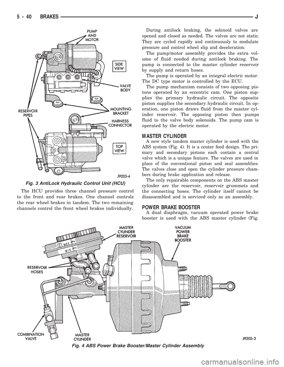
The HCU provides three channel pressure control
to the front and rear brakes. One channel controls
the rear wheel brakes in tandem. The two remaining
channels control the front wheel brakes individually.
During antilock braking, the solenoid valves are
opened and closed as needed. The valves are not static.
They are cycled rapidly and continuously to modulate
pressure and control wheel slip and deceleration.
The pump/motor assembly provides the extra vol-
ume of fluid needed during antilock braking. The
pump is connected to the master cylinder reservoir
by supply and return hoses.
The pump is operated by an integral electric motor.
The DC type motor is controlled by the ECU.
The pump mechanism consists of two opposing pis-
tons operated by an eccentric cam. One piston sup-
plies the primary hydraulic circuit. The opposite
piston supplies the secondary hydraulic circuit. In op-
eration, one piston draws fluid from the master cyl-
inder reservoir. The opposing piston then pumps
fluid to the valve body solenoids. The pump cam is
operated by the electric motor.
MASTER CYLINDER
A new style tandem master cylinder is used with the
ABS system (Fig. 4). It is a center feed design. The pri-
mary and secondary pistons each contain a central
valve which is a unique feature. The valves are used in
place of the conventional piston and seal assemblies.
The valves close and open the cylinder pressure cham-
bers during brake application and release.
The only repairable components on the ABS master
cylinder are the reservoir, reservoir grommets and
the connecting hoses. The cylinder itself cannot be
disassembled and is serviced only as an assembly.
POWER BRAKE BOOSTER
A dual diaphragm, vacuum operated power brake
booster is used with the ABS master cylinder (Fig.
Fig. 3 AntiLock Hydraulic Control Unit (HCU)
Fig. 4 ABS Power Brake Booster/Master Cylinder Assembly
5 - 40 BRAKESJ
Page 188 of 1784
4). The engine intake manifold serves as the vacuum
source for booster operation.
The booster is mounted on the engine compartment
side of the dash panel. The master cylinder is
mounted on attaching studs at the front of the
booster. The master cylinder central valves are di-
rectly actuated by the booster push rod.
The pedal travel sensor is mounted in the forward
face of the booster shell. The sensor plunger is actu-
ated by the booster diaphragm plate.
PEDAL TRAVEL SENSOR
The pedal travel sensor signals brake pedal posi-
tion to the antilock ECU. The sensor signal is based
on changes in electrical resistance. The resistance
changes occur in steps that are generated by changes
in brake pedal position. A resistance signal gener-
ated by changing brake pedal position, will cause the
ECU to run the antilock pump when necessary.
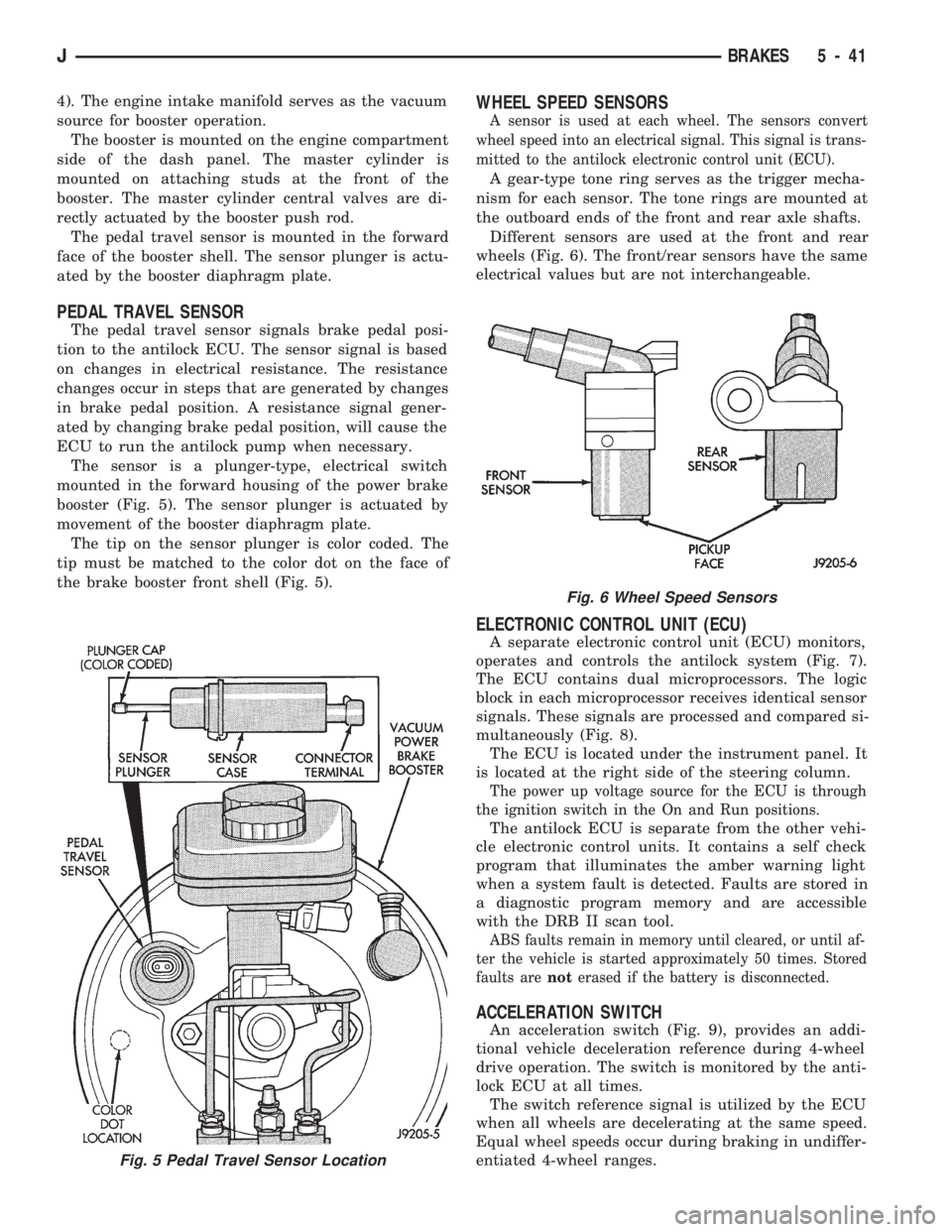
The sensor is a plunger-type, electrical switch
mounted in the forward housing of the power brake
booster (Fig. 5). The sensor plunger is actuated by
movement of the booster diaphragm plate.
The tip on the sensor plunger is color coded. The
tip must be matched to the color dot on the face of
the brake booster front shell (Fig. 5).
WHEEL SPEED SENSORS
A sensor is used at each wheel. The sensors convert
wheel speed into an electrical signal. This signal is trans-
mitted to the antilock electronic control unit (ECU).
A gear-type tone ring serves as the trigger mecha-
nism for each sensor. The tone rings are mounted at
the outboard ends of the front and rear axle shafts.
Different sensors are used at the front and rear
wheels (Fig. 6). The front/rear sensors have the same
electrical values but are not interchangeable.
ELECTRONIC CONTROL UNIT (ECU)
A separate electronic control unit (ECU) monitors,
operates and controls the antilock system (Fig. 7).
The ECU contains dual microprocessors. The logic
block in each microprocessor receives identical sensor
signals. These signals are processed and compared si-
multaneously (Fig. 8).
The ECU is located under the instrument panel. It
is located at the right side of the steering column.
The power up voltage source for the ECU is through
the ignition switch in the On and Run positions.
The antilock ECU is separate from the other vehi-
cle electronic control units. It contains a self check
program that illuminates the amber warning light
when a system fault is detected. Faults are stored in
a diagnostic program memory and are accessible
with the DRB II scan tool.
ABS faults remain in memory until cleared, or until af-
ter the vehicle is started approximately 50 times. Stored
faults arenoterased if the battery is disconnected.
ACCELERATION SWITCH
An acceleration switch (Fig. 9), provides an addi-
tional vehicle deceleration reference during 4-wheel
drive operation. The switch is monitored by the anti-
lock ECU at all times.
The switch reference signal is utilized by the ECU
when all wheels are decelerating at the same speed.
Equal wheel speeds occur during braking in undiffer-
entiated 4-wheel ranges.
Fig. 5 Pedal Travel Sensor Location
Fig. 6 Wheel Speed Sensors
JBRAKES 5 - 41