1994 JEEP CHEROKEE lock
[x] Cancel search: lockPage 26 of 1784

DRAINING ATF/FILTER REMOVAL
Drain the automatic transmission fluid (ATF) im-
mediately after stopping the engine (before the ATF
cools).
(1) Raise and support the vehicle.
(2) Loosen the transmission pan bolts and drain
the original ATF into an appropriate container. Re-
move the pan bolts, the pan and the gasket.
Care should be exercised when disposing used
ATF after it has been drained from a vehicle
transmission.
(3) Remove the screws and the ATF filter (Fig. 8).
Discard the filter.
FILTER INSTALLATION/ATF RE-FILL
(1) Install a replacement ATF filter. Tighten the
screws with 4 NIm (35 in. lbs.) torque.
(2) Clean the pan thoroughly. Install a replace-
ment gasket on the pan. Install the pan with the at-
taching bolts:
²model AW-4 transmission Ð tighten the pan bolts
with 7 NIm (60 in. lbs.) torque; and
²model 998 transmission Ð tighten the pan bolts
with 17 NIm (150 in. lbs.) torque.
(3) Remove the support and lower the vehicle.
(4) Pour approximately 4.7 liters (5 quarts) of ATF
into the filler tube. Use MerconŸ ATF for AW-4 au-
tomatic transmissions. Use MOPAR ATF PLUS type
7176 or equivalent, for 998 automatic transmissions.
(5) Place a block in front of and at the rear of one
wheel/tire to prevent vehicle movement.
(6) Start the engine and allow it to idle a few min-
utes.
(7) Apply the brake pedal and engage the parking
brake. Move the transmission selector lever through
all positions, then place the selector lever in NEU-
TRAL position.(8) With the transmission at normal operating
temperature, observe the ATF level on the dipstick.
Add ATF (if necessary) to raise the level to the
FULL mark on the dipstick.Only 0.5 liter (1.0 pint)
will raise the level from the ADD mark to the
FULL mark when the ATF is at normal operat-
ing temperature.
(9) Inspect for fluid leaks and correct as necessary.
(10) Remove the wheel/tire blocks.
TRANSFER CASE
RECOMMENDED MAINTENANCE
The fluid (ATF) level in transfer cases should be
determined at the same time as the engine oil is
changed and the oil filter is replaced. Add ATF as
necessary.
In addition, transfer case ATF should be changed
after each 48 000-km (30,000-miles) interval of vehi-
cle operation has elapsed.
FLUID SPECIFICATIONS
If it is necessary to add fluid to a transfer case (or
when the fluid is changed), use MOPAR ATF PLUS
type 7176 or an equivalent MerconŸ/Dexron IIŸ
ATF.
FLUID LEVEL
The transfer case fill-hole plug is located at the
rear of the housing (Fig. 9).
Determine the transfer case fluid (ATF) level ac-
cording to the following procedure.
(1) Raise and support the vehicle.
(2) Remove the fill-hole plug from the transfer
case. The ATF level should be at the bottom edge of
the fill hole. The level can be slightly below the bot-
tom edge of the fill hole if the fluid is cold.
Fig. 9 Transfer CaseÐTypical
Fig. 8 ATF FilterÐTypical
JLUBRICATION AND MAINTENANCE 0 - 25
Page 34 of 1784
(5) Inspect the reservoir rubber diaphragm seal for
cracks, cuts and distortion.
(6) Inspect the brake fluid tubing fittings and the
master cylinder housing for indications of fluid leak-
age. Repair as necessary.
(7) Install the brake fluid reservoir cover.
ANTI-LOCK BRAKE SYSTEMÐXJ VEHICLES
The anti-lock brake system fluid reservoir for XJ
Vehicles is located in the engine compartment at the
left side of the dash panel.
(1) Turn the ignition switch ON and allow the
pump motor to operate until it automatically de-en-
ergizes.
(2) Clean the cover before removing it.
CAUTION: Over-filling could cause fluid overflow
and possible reservoir damage when the pump mo-
tor energizes.
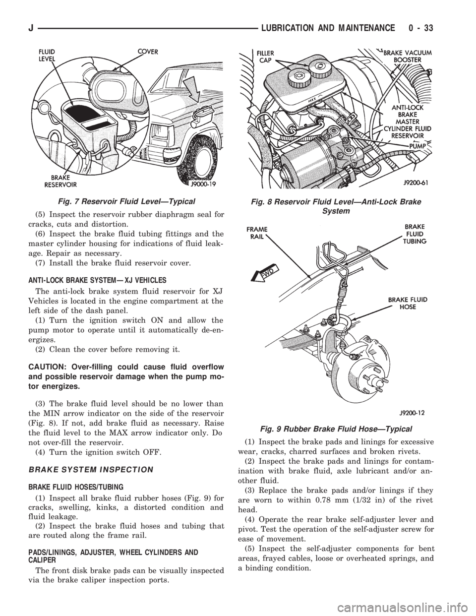
(3) The brake fluid level should be no lower than
the MIN arrow indicator on the side of the reservoir
(Fig. 8). If not, add brake fluid as necessary. Raise
the fluid level to the MAX arrow indicator only. Do
not over-fill the reservoir.
(4) Turn the ignition switch OFF.
BRAKE SYSTEM INSPECTION
BRAKE FLUID HOSES/TUBING
(1) Inspect all brake fluid rubber hoses (Fig. 9) for
cracks, swelling, kinks, a distorted condition and
fluid leakage.
(2) Inspect the brake fluid hoses and tubing that
are routed along the frame rail.
PADS/LININGS, ADJUSTER, WHEEL CYLINDERS AND
CALIPER
The front disk brake pads can be visually inspected
via the brake caliper inspection ports.(1) Inspect the brake pads and linings for excessive
wear, cracks, charred surfaces and broken rivets.
(2) Inspect the brake pads and linings for contam-
ination with brake fluid, axle lubricant and/or an-
other fluid.
(3) Replace the brake pads and/or linings if they
are worn to within 0.78 mm (1/32 in) of the rivet
head.
(4) Operate the rear brake self-adjuster lever and
pivot. Test the operation of the self-adjuster screw for
ease of movement.
(5) Inspect the self-adjuster components for bent
areas, frayed cables, loose or overheated springs, and
a binding condition.
Fig. 7 Reservoir Fluid LevelÐTypicalFig. 8 Reservoir Fluid LevelÐAnti-Lock Brake
System
Fig. 9 Rubber Brake Fluid HoseÐTypical
JLUBRICATION AND MAINTENANCE 0 - 33
Page 36 of 1784

(4) Extra close attention should be given to exter-
nal key lock cylinders during the autumn and winter
months to ensure protection from water and ice.(5) Extra close attention should also be given to
the hood latch components to ensure proper function-
ing.
HEADLAMPS
RECOMMENDED MAINTENANCE
Approximately every six months the headlamps
should be displayed on a vertical test surface. This
will ensure that the headlamps are positioned for
safe night-time driving.
BEAM AIM ADJUSTMENT
(1) Changes in the vehicle front and rear suspen-
sion will alter the headlamp beam patterns and this
can cause unsafe night-time driving conditions.
(2) If a vehicle is loaded the headlamp beam pat-
terns should be displayed on an vertical test surface
and the headlamps re-aimed.
(3) Observe the headlamp beam patterns on an ap-
propriate vertical test surface and, if necessary, ad-
just the headlamp beam aim.
(4) If necessary, refer to Group 8LÐLamps for
headlamp aim adjustment procedures.
BODY LUBRICANT SPECIFICATIONS
Fig. 11 Hood Hinge LubricationÐXJ Vehicles
JLUBRICATION AND MAINTENANCE 0 - 35
Page 57 of 1784
MODEL 30 AXLE AND TUBE AXLE (2WD)
INDEX
page page
Axle Bushing Replacement................. 32
Axle Shaft Ð Cardan U-Joint................ 25
Axle Specifications....................... 46
Backlash and Contact Pattern Analysis........ 44
Cleaning/Inspection....................... 35
Differential and Pinion Measurement.......... 38
Differential Assembly...................... 36
Differential Disassembly.................... 34
Differential Installation..................... 43
Differential Removal...................... 32
Differential Shim Pack Measurement and Adjustment.42
Drive Axle Assembly ReplacementÐXJ Vehicles . 21
Drive Axle Assembly ReplacementÐYJ Vehicles . 21Final Assembly.......................... 44
Hub Bearing and Axle Shaft................ 24
Information............................. 20
Inner Axle Shaft Oil Seal Replacement........ 33
Lubricant Change........................ 22
Lubricant Specifications.................... 20
Pinion Gear Assembly/Installation............ 40
Pinion Gear Depth Information.............. 37
Pinion Removal/Disassembly................ 34
Pinion Seal Replacement.................. 23
Steering Knuckle and Ball Studs............. 30
Vacuum Disconnect Axle Ð YJ Vehicles....... 26
INFORMATION
The housing for Model 30 front axles consists of an
iron center casting (differential housing) with axle
shaft tubes extending from either side. The tubes are
pressed into and welded to the differential housing to
form a one-piece axle housing.
The integral type housing, hypoid gear design has
the centerline of the pinion set above the centerline
of the ring gear.
The axle has a fitting for a vent hose used to re-
lieve internal pressure caused by lubricant vaporiza-
tion and internal expansion.
The axles are equipped with semi-floating axle
shafts, meaning that loads are supported by the hub
bearings. The axle shafts are retained by nuts at the
hub bearings. The hub bearings are bolted to the
steering knuckle at the outboard end of the axle tube
yoke. The hub bearings are serviced as an assembly.
The axles are equipped with ABS brake sensors.
The sensors are attached to the knuckle assemblies
and tone rings are pressed on the axle shaft.Use
care when removing axle shafts as NOT to dam-
age the tone wheel or the sensor.
The stamped steel cover provides a means for in-
spection and servicing the differential.
The Model 30 axle has the assembly part number
and gear ratio listed on a tag. The tag is attached to
the housing cover. Build date identification codes are
stamped on the axle shaft tube cover side.
The differential case is a one-piece design. The dif-
ferential pinion mate shaft is retained with a roll
pin. Differential bearing preload and ring gear back-
lash is adjusted by the use of shims (select thick-
ness). The shims are located between the differential
bearing cones and case. Pinion bearing preload is set
and maintained by the use of collapsible spacer.
PINION GEAR DEPTH MEASUREMENT WITH
PINION GAUGE SET 6774, Pinion Block 6733 and
Dial Indicator C-3339 is performed when;²Axle/differential housing is being replaced
²Original pinion depth shim pack is lost or mis-
placed
²Replacing the differential case
²Original differential bearing shim pack is lost or
misplaced
COMMAND-TRACÐYJ VEHICLES
The Command-Trac system is a vacuum disconnect
axle. The system has a two-piece axle shaft coupled
together by a shift collar. For two-wheel drive oper-
ation, the vacuum motor and shift fork disengages
the axle shaft splines. For four-wheel drive opera-
tion, the vacuum motor and shift fork engages the
splines.
SELEC-TRACÐXJ VEHICLES
The Selec-Trac system is a non-disconnect axle.
Shifting from two-wheel to four-wheel drive is at the
transfer case.
For XJ vehicles equipped withSelec-Tracand
ABS brake system, refer to Group 5ÐBrakes for ad-
ditional service information.
LUBRICANT SPECIFICATIONS
Multi-purpose, hypoid gear lubricant should be
used for Model 30 axles. The lubricant should have
MIL-L-2105C and API GL 5 quality specifications.
MOPARtHypoid Gear Lubricant conforms to both of
these specifications.
²The factory fill for the Model 30 axle is SAE 75W
gear lubricant.Do not use heavier weight lubri-
cant, this will cause axle engagement difficulties.
²The factory installed lubricant quantity for the
NON-DISCONNECT TYPE AXLE is 5061 fluid oz..
²The factory installed lubricant quantity for the
VACUUM-DISCONNECT TYPE AXLE is 5661 fluid
oz..
2 - 20 FRONT SUSPENSION AND AXLEJ
Page 71 of 1784
DIFFERENTIAL DISASSEMBLY
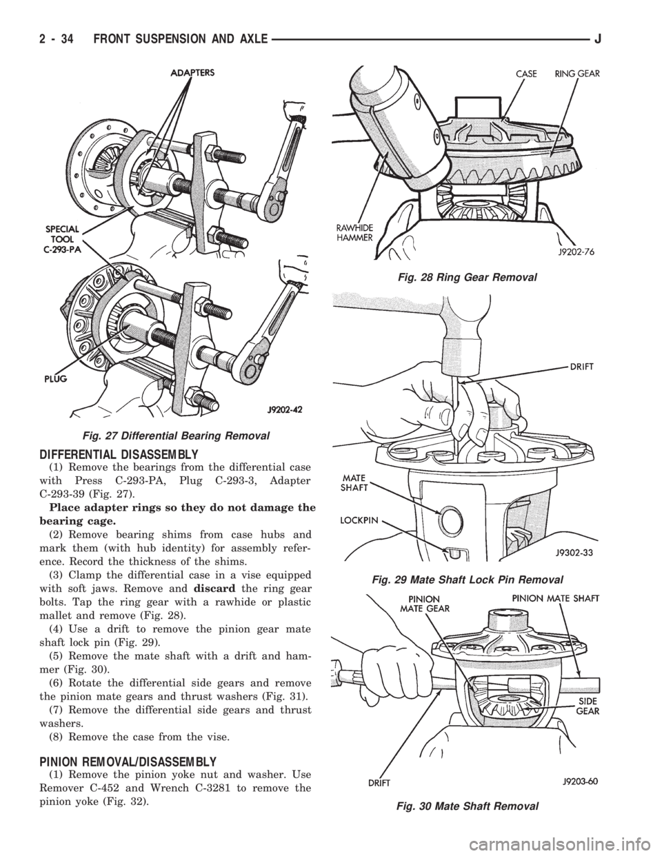
(1) Remove the bearings from the differential case
with Press C-293-PA, Plug C-293-3, Adapter
C-293-39 (Fig. 27).
Place adapter rings so they do not damage the
bearing cage.
(2) Remove bearing shims from case hubs and
mark them (with hub identity) for assembly refer-
ence. Record the thickness of the shims.
(3) Clamp the differential case in a vise equipped
with soft jaws. Remove anddiscardthe ring gear
bolts. Tap the ring gear with a rawhide or plastic
mallet and remove (Fig. 28).
(4) Use a drift to remove the pinion gear mate
shaft lock pin (Fig. 29).
(5) Remove the mate shaft with a drift and ham-
mer (Fig. 30).
(6) Rotate the differential side gears and remove
the pinion mate gears and thrust washers (Fig. 31).
(7) Remove the differential side gears and thrust
washers.
(8) Remove the case from the vise.
PINION REMOVAL/DISASSEMBLY
(1) Remove the pinion yoke nut and washer. Use
Remover C-452 and Wrench C-3281 to remove the
pinion yoke (Fig. 32).
Fig. 27 Differential Bearing Removal
Fig. 28 Ring Gear Removal
Fig. 29 Mate Shaft Lock Pin Removal
Fig. 30 Mate Shaft Removal
2 - 34 FRONT SUSPENSION AND AXLEJ
Page 73 of 1784
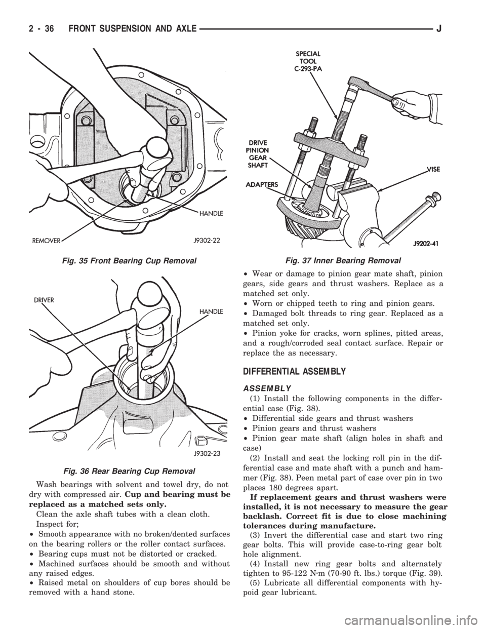
Wash bearings with solvent and towel dry, do not
dry with compressed air.Cup and bearing must be
replaced as a matched sets only.
Clean the axle shaft tubes with a clean cloth.
Inspect for;
²Smooth appearance with no broken/dented surfaces
on the bearing rollers or the roller contact surfaces.
²Bearing cups must not be distorted or cracked.
²Machined surfaces should be smooth and without
any raised edges.
²Raised metal on shoulders of cup bores should be
removed with a hand stone.²Wear or damage to pinion gear mate shaft, pinion
gears, side gears and thrust washers. Replace as a
matched set only.
²Worn or chipped teeth to ring and pinion gears.
²Damaged bolt threads to ring gear. Replaced as a
matched set only.
²Pinion yoke for cracks, worn splines, pitted areas,
and a rough/corroded seal contact surface. Repair or
replace the as necessary.
DIFFERENTIAL ASSEMBLY
ASSEMBLY
(1) Install the following components in the differ-
ential case (Fig. 38).
²Differential side gears and thrust washers
²Pinion gears and thrust washers
²Pinion gear mate shaft (align holes in shaft and
case)
(2) Install and seat the locking roll pin in the dif-
ferential case and mate shaft with a punch and ham-
mer (Fig. 38). Peen metal part of case over pin in two
places 180 degrees apart.
If replacement gears and thrust washers were
installed, it is not necessary to measure the gear
backlash. Correct fit is due to close machining
tolerances during manufacture.
(3) Invert the differential case and start two ring
gear bolts. This will provide case-to-ring gear bolt
hole alignment.
(4) Install new ring gear bolts and alternately
tighten to 95-122 Nzm (70-90 ft. lbs.) torque (Fig. 39).
(5) Lubricate all differential components with hy-
poid gear lubricant.
Fig. 35 Front Bearing Cup Removal
Fig. 36 Rear Bearing Cup Removal
Fig. 37 Inner Bearing Removal
2 - 36 FRONT SUSPENSION AND AXLEJ
Page 76 of 1784
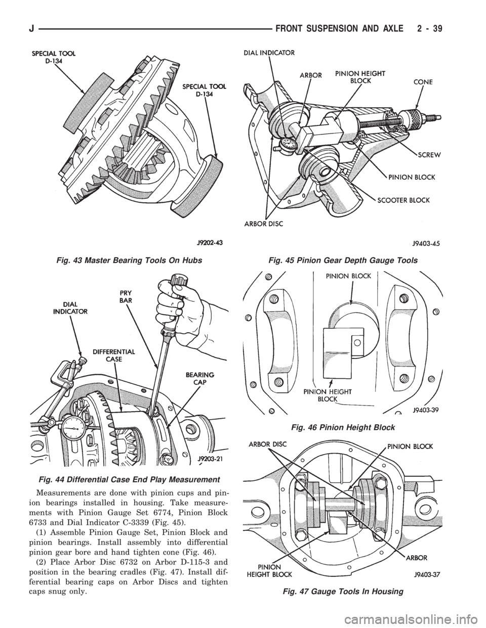
Measurements are done with pinion cups and pin-
ion bearings installed in housing. Take measure-
ments with Pinion Gauge Set 6774, Pinion Block
6733 and Dial Indicator C-3339 (Fig. 45).
(1) Assemble Pinion Gauge Set, Pinion Block and
pinion bearings. Install assembly into differential
pinion gear bore and hand tighten cone (Fig. 46).
(2) Place Arbor Disc 6732 on Arbor D-115-3 and
position in the bearing cradles (Fig. 47). Install dif-
ferential bearing caps on Arbor Discs and tighten
caps snug only.
Fig. 45 Pinion Gear Depth Gauge Tools
Fig. 46 Pinion Height Block
Fig. 47 Gauge Tools In Housing
Fig. 43 Master Bearing Tools On Hubs
Fig. 44 Differential Case End Play Measurement
JFRONT SUSPENSION AND AXLE 2 - 39
Page 77 of 1784
Arbor Discs have different steps to fit other
axle sizes. Pick correct size step for axle being
serviced.
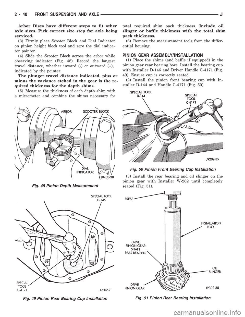
(3) Firmly place Scooter Block and Dial Indicator
on pinion height block tool and zero the dial indica-
tor pointer.
(4) Slide the Scooter Block across the arbor while
observing indicator (Fig. 48). Record the longest
travel distance, whether inward (-) or outward (+),
indicated by the pointer.
The plunger travel distance indicated, plus or
minus the variance etched in the gear is the re-
quired thickness for the depth shims.
(5) Measure the thickness of each depth shim with
a micrometer and combine the shims necessary fortotal required shim pack thickness.Include oil
slinger or baffle thickness with the total shim
pack thickness.
(6) Remove the measurement tools from the differ-
ential housing.
PINION GEAR ASSEMBLY/INSTALLATION
(1) Place the shims (and baffle if equipped) in the
pinion gear rear bearing bore. Install the bearing cup
with Installer D-146 and Driver Handle C-4171 (Fig.
49). Ensure cup is correctly seated.
(2) Install the pinion front bearing cup with In-
staller D-144 and Handle C-4171 (Fig. 50).
(3) Install the rear bearing and oil slinger on the
pinion gear with Installer W-262 until completely
seated (Fig. 51).
Fig. 48 Pinion Depth Measurement
Fig. 49 Pinion Rear Bearing Cup Installation
Fig. 50 Pinion Front Bearing Cup Installation
Fig. 51 Pinion Rear Bearing Installation
2 - 40 FRONT SUSPENSION AND AXLEJ