1994 JEEP CHEROKEE lock
[x] Cancel search: lockPage 256 of 1784
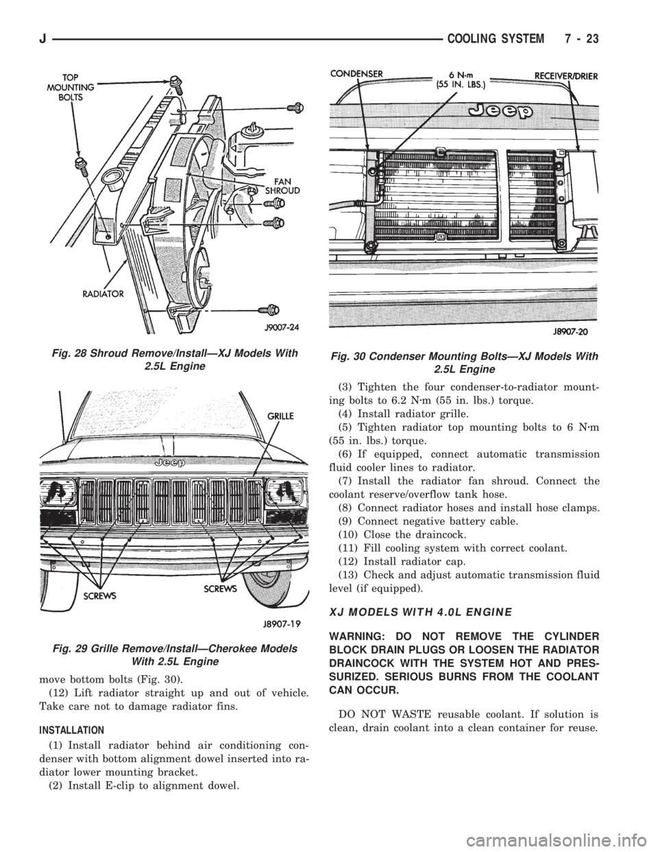
move bottom bolts (Fig. 30).
(12) Lift radiator straight up and out of vehicle.
Take care not to damage radiator fins.
INSTALLATION
(1) Install radiator behind air conditioning con-
denser with bottom alignment dowel inserted into ra-
diator lower mounting bracket.
(2) Install E-clip to alignment dowel.(3) Tighten the four condenser-to-radiator mount-
ing bolts to 6.2 Nzm (55 in. lbs.) torque.
(4) Install radiator grille.
(5) Tighten radiator top mounting bolts to 6 Nzm
(55 in. lbs.) torque.
(6) If equipped, connect automatic transmission
fluid cooler lines to radiator.
(7) Install the radiator fan shroud. Connect the
coolant reserve/overflow tank hose.
(8) Connect radiator hoses and install hose clamps.
(9) Connect negative battery cable.
(10) Close the draincock.
(11) Fill cooling system with correct coolant.
(12) Install radiator cap.
(13) Check and adjust automatic transmission fluid
level (if equipped).
XJ MODELS WITH 4.0L ENGINE
WARNING: DO NOT REMOVE THE CYLINDER
BLOCK DRAIN PLUGS OR LOOSEN THE RADIATOR
DRAINCOCK WITH THE SYSTEM HOT AND PRES-
SURIZED. SERIOUS BURNS FROM THE COOLANT
CAN OCCUR.
DO NOT WASTE reusable coolant. If solution is
clean, drain coolant into a clean container for reuse.
Fig. 28 Shroud Remove/InstallÐXJ Models With
2.5L Engine
Fig. 29 Grille Remove/InstallÐCherokee Models
With 2.5L Engine
Fig. 30 Condenser Mounting BoltsÐXJ Models With
2.5L Engine
JCOOLING SYSTEM 7 - 23
Page 258 of 1784
(7) If equipped, connect automatic transmission
fluid cooler lines. If equipped with remote cooler, at-
tach cooler line to bracket at bottom of radiator.
(8) Install electric cooling fan (if equipped). Insert
alignment tabs at bottom of fan shroud into slots in
bracket at bottom of radiator. Tighten mounting
bolts to 4 Nzm (36 in. lbs.) torque.
(9) Connect electric cooling fan electrical connec-
tor.(10) Install mechanical cooling fan shroud. Insert
alignment tabs at bottom of shroud into slots in
bracket at bottom of radiator. Tighten mounting
bolts to 4 Nzm (36 in. lbs.) torque (Fig. 32).
(11) Close radiator draincock.
(12) Install grille.
(13) Connect negative battery cable.
(14) Fill cooling system with correct coolant. Refer
to the Coolant section of this group.
(15) Install pressure cap.
(16) Check and adjust automatic transmission fluid
level (if equipped).
YJ MODELS
WARNING: DO NOT REMOVE THE CYLINDER
BLOCK DRAIN PLUGS OR LOOSEN THE RADIATOR
DRAINCOCK WITH THE SYSTEM HOT AND PRES-
SURIZED. SERIOUS BURNS FROM THE COOLANT
CAN OCCUR.
DO NOT WASTE reusable coolant. If solution is
clean, drain coolant into a clean container for reuse.
WARNING: CONSTANT TENSION HOSE CLAMPS
ARE USED ON MOST COOLING SYSTEM HOSES.
WHEN REMOVING OR INSTALLING, USE ONLY
TOOLS DESIGNED FOR SERVICING THIS TYPE OF
CLAMP, SUCH AS SPECIAL CLAMP TOOL (NUM-
BER 6094) (FIG. 26). SNAP-ON CLAMP TOOL (NUM-
BER HPC-20) MAY BE USED FOR LARGER
CLAMPS. ALWAYS WEAR SAFETY GLASSES
WHEN SERVICING CONSTANT TENSION CLAMPS.
CAUTION: A number or letter is stamped into the
tongue of constant tension clamps. If replacement
is necessary, use only an original equipment clamp
with matching number or letter.
REMOVAL
(1) Disconnect negative battery cable at battery.
(2) Observe the previousWARNINGS.Remove
the radiator cap.
(3) Position drain pan under draincock. Open radi-
ator draincock and drain radiator.
(4) Remove radiator upper and lower hose clamps
and hoses.
(5) Disconnect coolant reserve/overflow tank hose
from radiator.
(6) Remove fan shroud bolts and push shroud back
onto fan (Fig. 35).
(7) If equipped, disconnect and plug automatic
transmission fluid cooler lines.
(8) Remove radiator attaching bolts.
(9) Lift radiator straight up and out of vehicle tak-
ing care not to damage radiator fins.
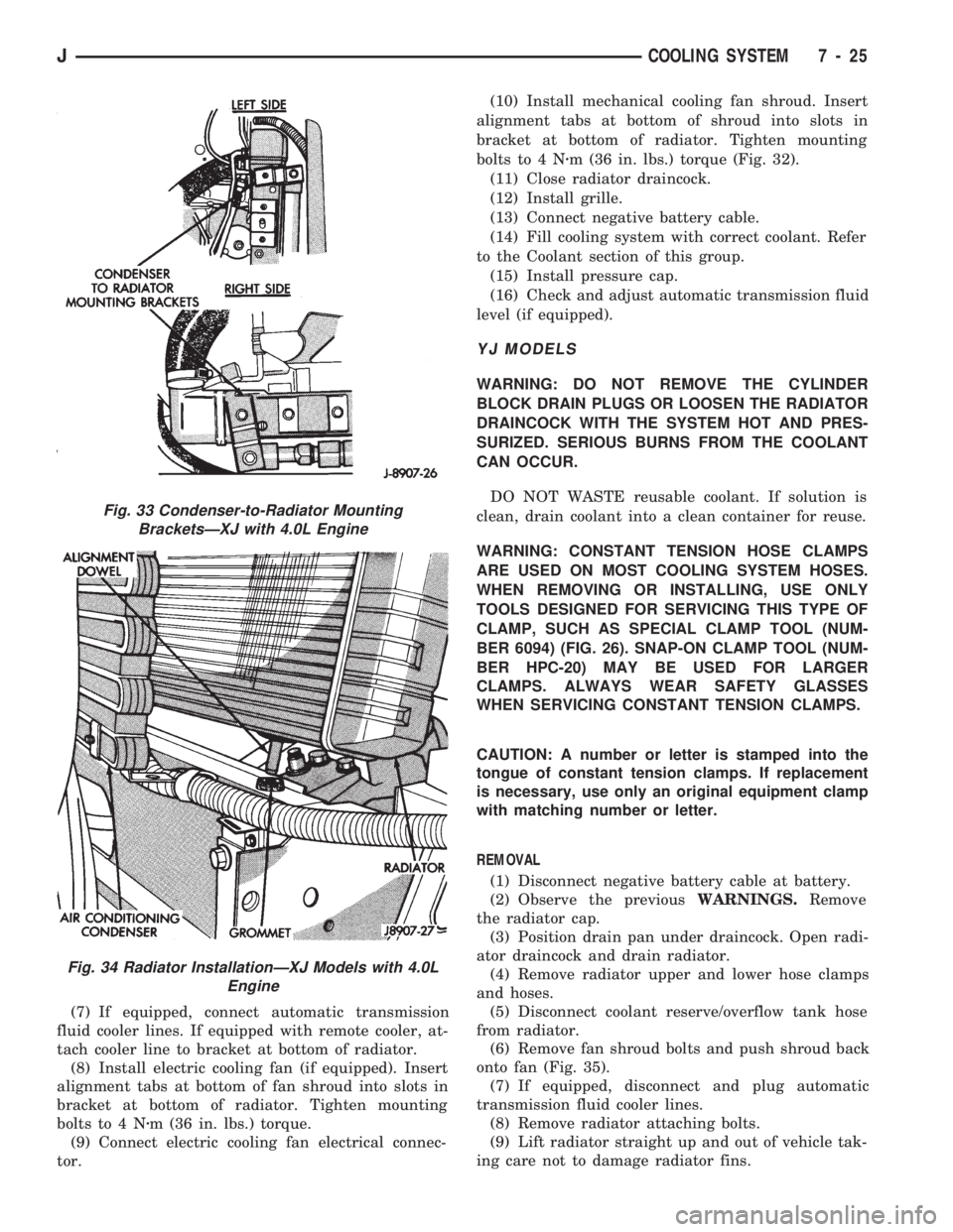
Fig. 33 Condenser-to-Radiator Mounting
BracketsÐXJ with 4.0L Engine
Fig. 34 Radiator InstallationÐXJ Models with 4.0L
Engine
JCOOLING SYSTEM 7 - 25
Page 260 of 1784
speed of the fan to a predetermined maximum level
at higher engine speeds. A bimetallic spring coil is
located on the front face. This spring coil reacts to
the temperature of the radiator discharge air. It en-
gages the viscous fan drive for higher fan speed if
the air temperature from the radiator rises above a
certain point. Until additional engine cooling is nec-
essary, the fan will remain at a reduced rpm regard-
less of engine speed.
Only when sufficient heat is present, will the vis-
cous fan drive engage. This is when the air flowing
through the radiator core causes a reaction from the
bimetallic coil. It then increases fan speed to provide
the necessary additional engine cooling.
Once the engine has cooled, the radiator discharge
temperature will drop. The bimetallic coil again re-
acts and the fan speed is reduced to the previous dis-
engaged speed.
CAUTION: Engines equipped with serpentine drive
belts have reverse rotating fans and viscous fan
drives. They are marked with the word REVERSE to
designate their usage. Installation of the wrong fan
or viscous fan drive can result in engine overheat-
ing.
VISCOUS FAN DRIVE TEST
The cooling system must be in good condition. This
is checked prior to performing the following test. It
also will ensure against excessively high coolant
temperature.
CAUTION: Be sure that there is adequate fan blade
clearance before drilling.(1) Drill a 3.18-mm (1/8-in) diameter hole in the
top center of the fan shroud.
(2) Obtain a dial thermometer with an 8 inch stem
(or equivalent). It should have a range of -18É-to-
105ÉC (0É-to-220É F). Insert thermometer through the
hole in the shroud. Be sure that there is adequate
clearance from the fan blades.
(3) Connect a tachometer and an engine ignition
timing light (timing light is to be used as a strobe
light).
(4) Block the air flow through the radiator. Secure
a sheet of plastic in front of the radiator (or air con-
ditioner condenser). Use tape at the top to secure the
plastic and be sure that the air flow is blocked.
(5) Be sure that the air conditioner (if equipped) is
turned off.
WARNING: USE EXTREME CAUTION WHEN THE
ENGINE IS OPERATING. DO NOT STAND IN A DI-
RECT LINE WITH THE FAN. DO NOT PUT YOUR
HANDS NEAR THE PULLEYS, BELTS OR FAN. DO
NOT WEAR LOOSE CLOTHING.
(6) Start the engine and operate at 2400 rpm with
the timing light (strobe light) aimed at the fan
blades. Within ten minutes the air temperature (in-
dicated on the dial thermometer) should be 88É C
(190É F). Satisfactory operation of the fan drive re-
quires that it engage before or at 88É C (190É F). En-
gagement is distinguishable by a definite increase in
flow noise. The timing light also will indicate an in-
crease in the speed of the fan.
(7) When the air temperature reaches 88É C (190É
F), remove the plastic sheet. Satisfactory operation of
the viscous fan requires the air temperature to drop
20É F (11É C) or more. A definite decrease of audible-
fan-air-flow-noise should be noticed. Replace defec-
tive fan assemblies.
VISCOUS FAN DRIVE REPLACEMENT
REMOVAL
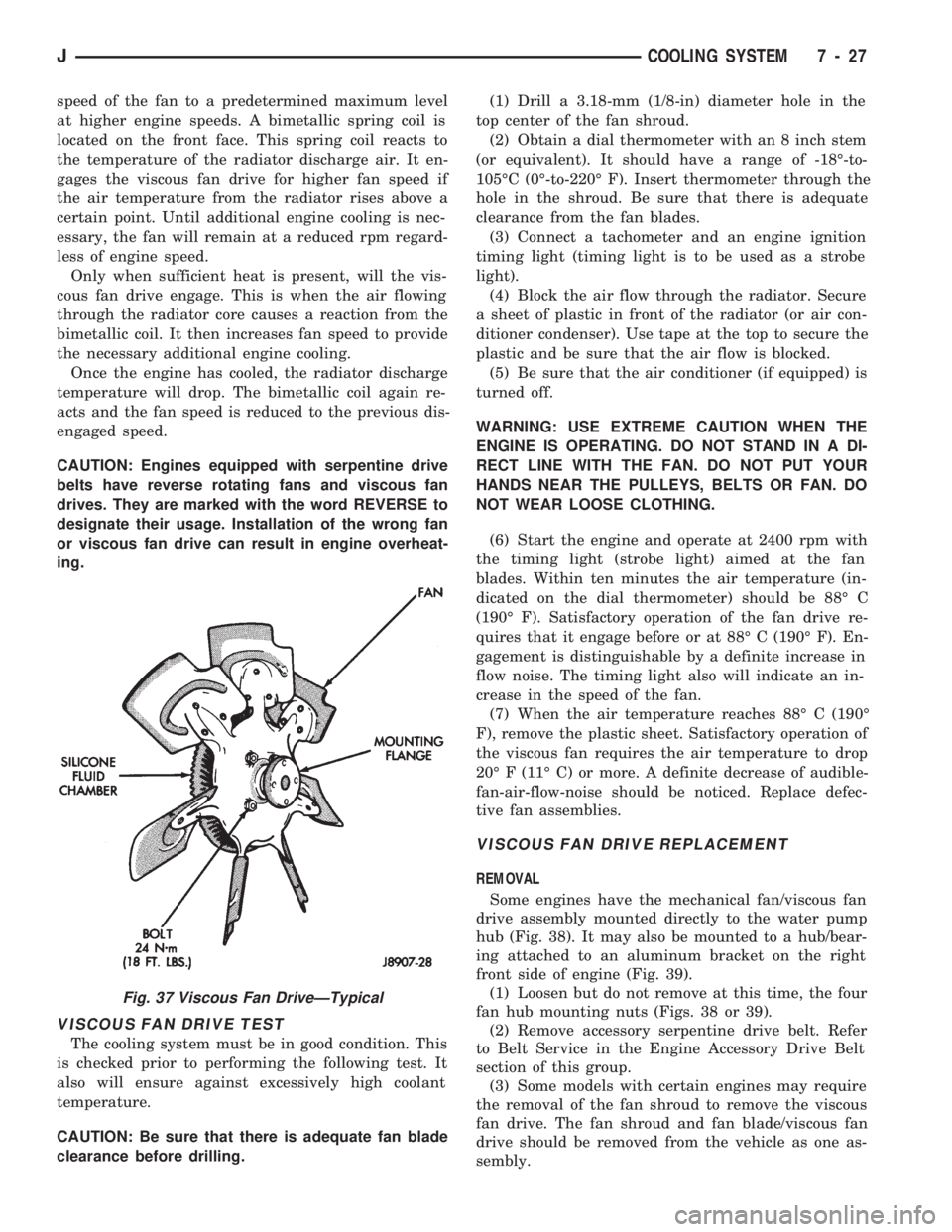
Some engines have the mechanical fan/viscous fan
drive assembly mounted directly to the water pump
hub (Fig. 38). It may also be mounted to a hub/bear-
ing attached to an aluminum bracket on the right
front side of engine (Fig. 39).
(1) Loosen but do not remove at this time, the four
fan hub mounting nuts (Figs. 38 or 39).
(2) Remove accessory serpentine drive belt. Refer
to Belt Service in the Engine Accessory Drive Belt
section of this group.
(3) Some models with certain engines may require
the removal of the fan shroud to remove the viscous
fan drive. The fan shroud and fan blade/viscous fan
drive should be removed from the vehicle as one as-
sembly.
Fig. 37 Viscous Fan DriveÐTypical
JCOOLING SYSTEM 7 - 27
Page 267 of 1784
BELT TENSIONÐRIGHT HAND DRIVE (RHD)
XJ MODELS WITH 4.0L ENGINE
It is not necessary to adjust belt tension on RHD
vehicles if equipped with a 4.0L engine. The engine
is equipped with an automatic belt tensioner (Fig. 7).
The tensioner maintains correct belt tension at all
times.Due to the use of this belt tensioner, DO
NOT attempt to use a belt tension gauge on this
engine.
BELT TENSION SPECIFICATIONS
Refer to the Specifications section at the end of this
group.
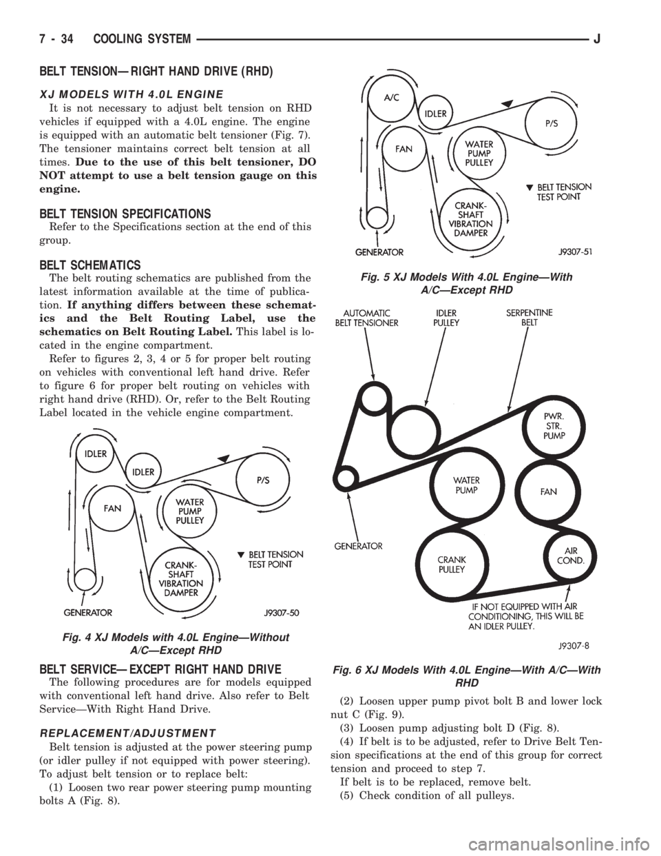
BELT SCHEMATICS
The belt routing schematics are published from the
latest information available at the time of publica-
tion.If anything differs between these schemat-
ics and the Belt Routing Label, use the
schematics on Belt Routing Label.This label is lo-
cated in the engine compartment.
Refer to figures 2, 3, 4 or 5 for proper belt routing
on vehicles with conventional left hand drive. Refer
to figure 6 for proper belt routing on vehicles with
right hand drive (RHD). Or, refer to the Belt Routing
Label located in the vehicle engine compartment.
BELT SERVICEÐEXCEPT RIGHT HAND DRIVE
The following procedures are for models equipped
with conventional left hand drive. Also refer to Belt
ServiceÐWith Right Hand Drive.
REPLACEMENT/ADJUSTMENT
Belt tension is adjusted at the power steering pump
(or idler pulley if not equipped with power steering).
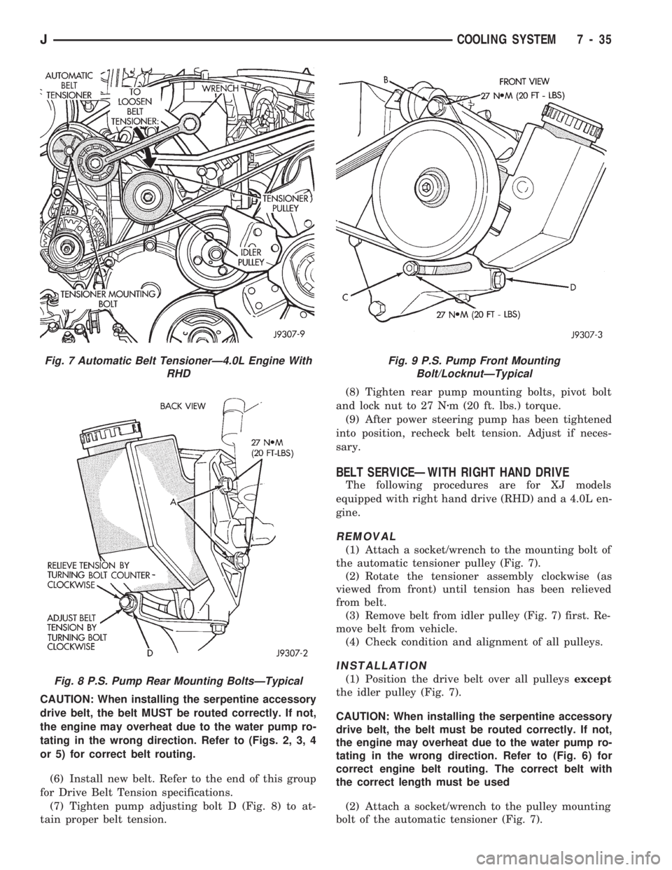
To adjust belt tension or to replace belt:
(1) Loosen two rear power steering pump mounting
bolts A (Fig. 8).(2) Loosen upper pump pivot bolt B and lower lock
nut C (Fig. 9).
(3) Loosen pump adjusting bolt D (Fig. 8).
(4) If belt is to be adjusted, refer to Drive Belt Ten-
sion specifications at the end of this group for correct
tension and proceed to step 7.
If belt is to be replaced, remove belt.
(5) Check condition of all pulleys.
Fig. 4 XJ Models with 4.0L EngineÐWithout
A/CÐExcept RHD
Fig. 5 XJ Models With 4.0L EngineÐWith
A/CÐExcept RHD
Fig. 6 XJ Models With 4.0L EngineÐWith A/CÐWith
RHD
7 - 34 COOLING SYSTEMJ
Page 268 of 1784
CAUTION: When installing the serpentine accessory
drive belt, the belt MUST be routed correctly. If not,
the engine may overheat due to the water pump ro-
tating in the wrong direction. Refer to (Figs. 2, 3, 4
or 5) for correct belt routing.
(6) Install new belt. Refer to the end of this group
for Drive Belt Tension specifications.
(7) Tighten pump adjusting bolt D (Fig. 8) to at-
tain proper belt tension.(8) Tighten rear pump mounting bolts, pivot bolt
and lock nut to 27 Nzm (20 ft. lbs.) torque.
(9) After power steering pump has been tightened
into position, recheck belt tension. Adjust if neces-
sary.
BELT SERVICEÐWITH RIGHT HAND DRIVE
The following procedures are for XJ models
equipped with right hand drive (RHD) and a 4.0L en-
gine.
REMOVAL
(1) Attach a socket/wrench to the mounting bolt of
the automatic tensioner pulley (Fig. 7).
(2) Rotate the tensioner assembly clockwise (as
viewed from front) until tension has been relieved
from belt.
(3) Remove belt from idler pulley (Fig. 7) first. Re-
move belt from vehicle.
(4) Check condition and alignment of all pulleys.
INSTALLATION
(1) Position the drive belt over all pulleysexcept
the idler pulley (Fig. 7).
CAUTION: When installing the serpentine accessory
drive belt, the belt must be routed correctly. If not,
the engine may overheat due to the water pump ro-
tating in the wrong direction. Refer to (Fig. 6) for
correct engine belt routing. The correct belt with
the correct length must be used
(2) Attach a socket/wrench to the pulley mounting
bolt of the automatic tensioner (Fig. 7).
Fig. 7 Automatic Belt TensionerÐ4.0L Engine With
RHD
Fig. 8 P.S. Pump Rear Mounting BoltsÐTypical
Fig. 9 P.S. Pump Front Mounting
Bolt/LocknutÐTypical
JCOOLING SYSTEM 7 - 35
Page 269 of 1784
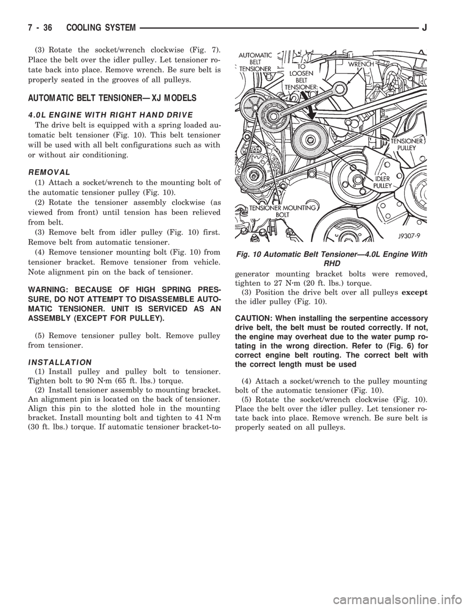
(3) Rotate the socket/wrench clockwise (Fig. 7).
Place the belt over the idler pulley. Let tensioner ro-
tate back into place. Remove wrench. Be sure belt is
properly seated in the grooves of all pulleys.
AUTOMATIC BELT TENSIONERÐXJ MODELS
4.0L ENGINE WITH RIGHT HAND DRIVE
The drive belt is equipped with a spring loaded au-
tomatic belt tensioner (Fig. 10). This belt tensioner
will be used with all belt configurations such as with
or without air conditioning.
REMOVAL
(1) Attach a socket/wrench to the mounting bolt of
the automatic tensioner pulley (Fig. 10).
(2) Rotate the tensioner assembly clockwise (as
viewed from front) until tension has been relieved
from belt.
(3) Remove belt from idler pulley (Fig. 10) first.
Remove belt from automatic tensioner.
(4) Remove tensioner mounting bolt (Fig. 10) from
tensioner bracket. Remove tensioner from vehicle.
Note alignment pin on the back of tensioner.
WARNING: BECAUSE OF HIGH SPRING PRES-
SURE, DO NOT ATTEMPT TO DISASSEMBLE AUTO-
MATIC TENSIONER. UNIT IS SERVICED AS AN
ASSEMBLY (EXCEPT FOR PULLEY).
(5) Remove tensioner pulley bolt. Remove pulley
from tensioner.
INSTALLATION
(1) Install pulley and pulley bolt to tensioner.
Tighten bolt to 90 Nzm (65 ft. lbs.) torque.
(2) Install tensioner assembly to mounting bracket.
An alignment pin is located on the back of tensioner.
Align this pin to the slotted hole in the mounting
bracket. Install mounting bolt and tighten to 41 Nzm
(30 ft. lbs.) torque. If automatic tensioner bracket-to-generator mounting bracket bolts were removed,
tighten to 27 Nzm (20 ft. lbs.) torque.
(3) Position the drive belt over all pulleysexcept
the idler pulley (Fig. 10).
CAUTION: When installing the serpentine accessory
drive belt, the belt must be routed correctly. If not,
the engine may overheat due to the water pump ro-
tating in the wrong direction. Refer to (Fig. 6) for
correct engine belt routing. The correct belt with
the correct length must be used
(4) Attach a socket/wrench to the pulley mounting
bolt of the automatic tensioner (Fig. 10).
(5) Rotate the socket/wrench clockwise (Fig. 10).
Place the belt over the idler pulley. Let tensioner ro-
tate back into place. Remove wrench. Be sure belt is
properly seated on all pulleys.
Fig. 10 Automatic Belt TensionerÐ4.0L Engine With
RHD
7 - 36 COOLING SYSTEMJ
Page 270 of 1784
ENGINE BLOCK HEATER
GENERAL INFORMATION
DESCRIPTION AND OPERATION
An optional engine block heater is available for all
models. The heater is equipped with a power cord.
The cord is attached to an engine compartment com-
ponent with tie-straps. The heater warms the engine
providing easier engine starting and faster warm-up
in low temperatures. The heater is mounted in a core
hole of the engine cylinder block (in place of a freeze
plug) with the heating element immersed in engine
coolant. Connect the power cord to a grounded 110-
120 volt AC electrical outlet with a grounded, three-
wire extension cord.
WARNING: DO NOT OPERATE ENGINE UNLESS
BLOCK HEATER CORD HAS BEEN DISCONNECTED
FROM POWER SOURCE AND SECURED IN PLACE.
BLOCK HEATER SPECIFICATIONS
²2.5L Engine: 115 Volts 400 Watts
²4.0L Engine: 120 Volts 600 Watts
REMOVAL
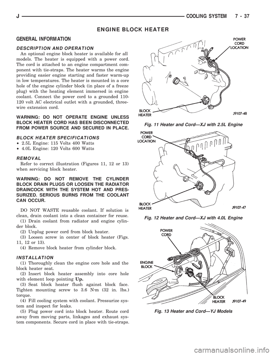
Refer to correct illustration (Figures 11, 12 or 13)
when servicing block heater.
WARNING: DO NOT REMOVE THE CYLINDER
BLOCK DRAIN PLUGS OR LOOSEN THE RADIATOR
DRAINCOCK WITH THE SYSTEM HOT AND PRES-
SURIZED. SERIOUS BURNS FROM THE COOLANT
CAN OCCUR.
DO NOT WASTE reusable coolant. If solution is
clean, drain coolant into a clean container for reuse.
(1) Drain coolant from radiator and engine cylin-
der block.
(2) Unplug power cord from block heater.
(3) Loosen screw in center of block heater (Figs.
11, 12 or 13).
(4) Remove block heater from cylinder block.
INSTALLATION
(1) Thoroughly clean the engine core hole and the
block heater seat.
(2) Insert block heater assembly into core hole
with element loop pointingUp.
(3) Seat block heater flush against block face.
Tighten mounting screw to 3.6 Nzm (32 in. lbs.)
torque.
(4) Fill cooling system with coolant. Pressurize sys-
tem and inspect for leaks.
(5) Plug power cord into block heater. Route cord
away from moving parts, linkages and exhaust sys-
tem components. Secure cord in place with tie-straps.
Fig. 11 Heater and CordÐXJ with 2.5L Engine
Fig. 12 Heater and CordÐXJ with 4.0L Engine
Fig. 13 Heater and CordÐYJ Models
JCOOLING SYSTEM 7 - 37
Page 274 of 1784
ELECTRICAL
GROUP INDEX
Group Group
AUDIO SYSTEMS....................... 8F
BATTERY/STARTER/GENERATOR SERVICE . . 8B
BATTERY/STARTING/CHARGING SYSTEMS
DIAGNOSTICS........................ 8A
CHIME/WARNING BUZZER SYSTEM....... 8U
HORNS............................... 8G
IGNITION SYSTEMS.................... 8D
INSTRUMENT PANEL AND GAUGES........ 8E
LAMPS............................... 8L
OVERHEAD CONSOLE................... 8CPOWER LOCKS........................ 8P
POWER MIRRORS...................... 8T
POWER SEAT.......................... 8R
POWER WINDOWS..................... 8S
REAR WINDOW DEFOGGER.............. 8N
TURN SIGNALS AND HAZARD WARNING
FLASHERS........................... 8J
VEHICLE SPEED CONTROL SYSTEM....... 8H
WINDSHIELD WIPERS AND WASHERS..... 8K
WIRING DIAGRAMS.................... 8W
BATTERY/STARTING/CHARGING SYSTEMS DIAGNOSTICS
CONTENTS
page page
BATTERY TEST PROCEDURES............. 2
ENGINE STARTER MOTOR TEST
PROCEDURES ON VEHICLE.............. 9GENERATOR TEST PROCEDURES ON
VEHICLE............................. 14
IGNITION OFF DRAW (IOD) DIAGNOSIS...... 8
USING ON-BOARD DIAGNOSTIC SYSTEM.... 19
GENERAL INFORMATION
The battery, starting, and charging systems oper-
ate with one another, and therefore, must be thor-
oughly tested as a complete system. In order for the
vehicle to start and charge properly, it must have a
battery that will perform to specifications. The
starter motor, generator, wiring, and electronics also
must perform within specifications. Group 8A covers
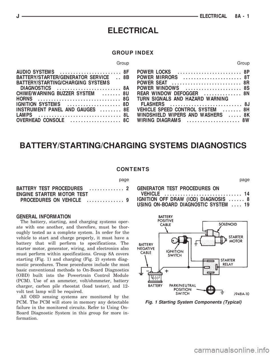
starting (Fig. 1) and charging (Fig. 2) system diag-
nostic procedures. These procedures include the most
basic conventional methods to On-Board Diagnostics
(OBD) built into the Powertrain Control Module
(PCM). Use of an ammeter, volt/ohmmeter, battery
charger, carbon pile rheostat (load tester), and 12-
volt test lamp will be required.
All OBD sensing systems are monitored by the
PCM. The PCM will store in memory any detectable
failure in the monitored circuits. Refer to Using On-
Board Diagnostic System in this group for more in-
formation.
Fig. 1 Starting System Components (Typical)
JELECTRICAL 8A - 1