1994 JEEP CHEROKEE lock
[x] Cancel search: lockPage 402 of 1784

TURN SIGNALS AND HAZARD WARNING FLASHER
CONTENTS
page page
HAZARD LAMPSÐXJ.................... 1
HAZARD LAMPSÐYJ.................... 2
TURN SIGNALSÐXJ..................... 1TURN SIGNALSÐYJ..................... 2
TURN/HAZARD SWITCH REPLACEMENT - ALL
MODELS............................. 3
TURN SIGNALSÐXJ
Refer to Section 8W - Wiring Diagrams for cir-
cuit wiring diagram.
DESCRIPTION
With the turn signal lever in its up or down posi-
tion and the ignition switch in ACCESSORY or ON,
current flows through the:
²turn/hazard switch
²selected turn indicator bulb
²front and rear turn signal bulbs
²and the front side marker bulb.
With the headlamps OFF, the turn and front side
marker lamps flash in unison.With the headlamps
ON, the turn and front side marker lamps flash al-
ternately.
DIAGNOSISÐTURN SIGNAL INOPERATIVE
(1) A turn signal indicator that does not flash usu-
ally indicates a burned out turn signal bulb. Check
for and replace if defective. System should now func-
tion properly. If not, go to next step.
High generator output voltage can burn out
lamps rapidly.(2) Remove and inspect 20 amp #8 fuse. Replace if
necessary. If OK, go to next step.
(3) Remove turn flasher, light blue can, located in
upper left corner of fuse block.
(4) Turn ignition switch to ACCESSORY. Check
for battery voltage at flasher bottom cavity on fuse
block. If OK, go to next step. If not, repair open cir-
cuit in wiring between turn flasher and #8 fuse.
(5) Turn ignition switch to ACCESSORY. Move
turn signal lever up or down. Replace turn flasher
with known good flasher. The lamps should flash. If
not, replace original flasher and go to next step.
(6) Turn ignition switch to OFF. Follow procedure
for turn/hazard switch replacement to locate steering
column connector. Unplug connector.
(7) Turn ignition switch to ACCESSORY. Check
for battery voltage at connector terminal L. If OK,
replace turn/hazard switch and check that lamps
flash. If not, repair open circuit in wiring between
turn flasher and steering column connector terminal
L.
HAZARD LAMPSÐXJ
Refer to Section 8W - Wiring Diagrams for cir-
cuit wiring diagram.
DESCRIPTION
With the hazard switch ON, current flows through
the:
²hazard flasher
²the turn/hazard switch
²two front turn signal bulbs
²two rear turn signal bulbs
²two front side marker bulbs
²and two turn indicator bulbs.
All of these bulbs will flash on and off.
DIAGNOSISÐHAZARD LAMPS INOPERATIVE
(1) Inspect 20 amp #F13 fuse in Power Distribu-
tion Center (PDC). The PDC is located in the engine
compartment, passenger side. For location of fuse,check underside of PDC cover. Replace if necessary.
If OK, go to next step.
(2) Remove hazard flasher (tin can) located in fuse
block.
(3) Check for battery voltage at the terminal on
the right (3 o'clock). If OK, go to next step. If not, re-
pair open circuit in wiring between #F13 fuse and
hazard flasher right terminal.
(4) Replace hazard flasher with known good
flasher. Activate hazard warning switch. Lamps
should flash. If not, replace original flasher and go to
next step.
(5) Follow procedure for turn/hazard switch re-
placement to locate steering column connector. Un-
plug connector.
(6) Check for battery voltage at connector terminal
K. If OK, replace turn/hazard switch. If not, repair
open circuit in wiring between hazard flasher and
steering column connector terminal K.
JTURN SIGNALS AND HAZARD WARNING FLASHER 8J - 1
Page 403 of 1784

TURN SIGNALSÐYJ
Refer to Section 8W - Wiring Diagrams for cir-
cuit wiring diagram.
DESCRIPTION
With the turn signal lever in its up or down posi-
tion and the ignition switch in ACCESSORY or ON,
current flows through the:
²turn/hazard switch
²selected turn indicator bulb
²front and rear turn signal bulbs
²front side marker bulb
With the headlamps OFF, the turn and side
marker lamps flash in unison.With the headlamps
ON, the turn and side marker lamps flash alter-
nately.
DIAGNOSINGÐTURN SIGNAL INOPERATIVE
(1) A turn signal indicator that does not flash usu-
ally indicates a burned out turn signal bulb. Check
for and replace if defective. System should now func-
tion properly. If not, go to next step.
High generator output voltage can burn out
lamps rapidly.
(2) Locate fuse block under driver's side of instru-
ment panel.(3) Remove and inspect 15 amp #4 fuse. Replace if
necessary. If OK, go to next step.
(4) Remove turn flasher, light blue can, located in
fuse block.
(5) Turn ignition switch to ACCESSORY. Check
for battery voltage at cavity on left (closest to hazard
flasher can). If OK, go to next step. If not, repair
open circuit in wiring between turn flasher and #4
fuse.
(6) Turn ignition switch to ACCESSORY. Move
turn signal lever up or down. Replace turn flasher
with known good flasher. The lamps should flash. If
not, replace original flasher and go to next step.
(7) Turn ignition switch to OFF. Follow procedure
for turn/hazard switch replacement to locate steering
column connector. Unplug connector.
(8) Turn ignition switch to ACCESSORY. Check
for battery voltage at connector terminal L. If OK,
replace turn/hazard switch. If not, repair open circuit
in wiring between turn flasher and steering column
connector terminal L.
HAZARD LAMPSÐYJ
Refer to Section 8W - Wiring Diagrams for cir-
cuit wiring diagram.
DESCRIPTION
With the hazard switch ON, current flows through
the:
²hazard flasher
²turn/hazard switch
²two front turn signal bulbs
²two rear turn signal bulbs
²two front side marker bulbs
²two turn indicator bulbs.
All of these bulbs will flash on and off.
DIAGNOSISÐHAZARD LAMPS INOPERATIVE
(1) Inspect 20 amp #F5 fuse in Power Distribution
Center (PDC). The PDC is located in the engine com-
partment, passenger side. For location of fuse, check
underside of PDC cover. Replace if necessary. If OK,
go to next step.(2) Remove hazard flasher (tin can) located in fuse
block.
(3) Check for battery voltage at the terminal on
the left. If OK, go to next step. If not, repair open cir-
cuit in wiring between #F5 fuse and hazard flasher
left terminal.
(4) Replace hazard flasher with known good
flasher. Activate hazard warning switch. Lamps
should flash. If not, replace original flasher and go to
next step.
(5) Follow procedure for turn/hazard switch re-
placement to locate steering column connector. Un-
plug connector.
(6) Check for battery voltage at connector terminal
K. If OK, replace turn/hazard switch. If not, repair
open circuit in wiring between hazard flasher and
steering column connector terminal K.
8J - 2 TURN SIGNALS AND HAZARD WARNING FLASHERJ
Page 404 of 1784
TURN/HAZARD SWITCH REPLACEMENT - ALL MODELS
(1) Disconnect negative cable from battery.
(2) Remove the horn button with a push and turn
motion.
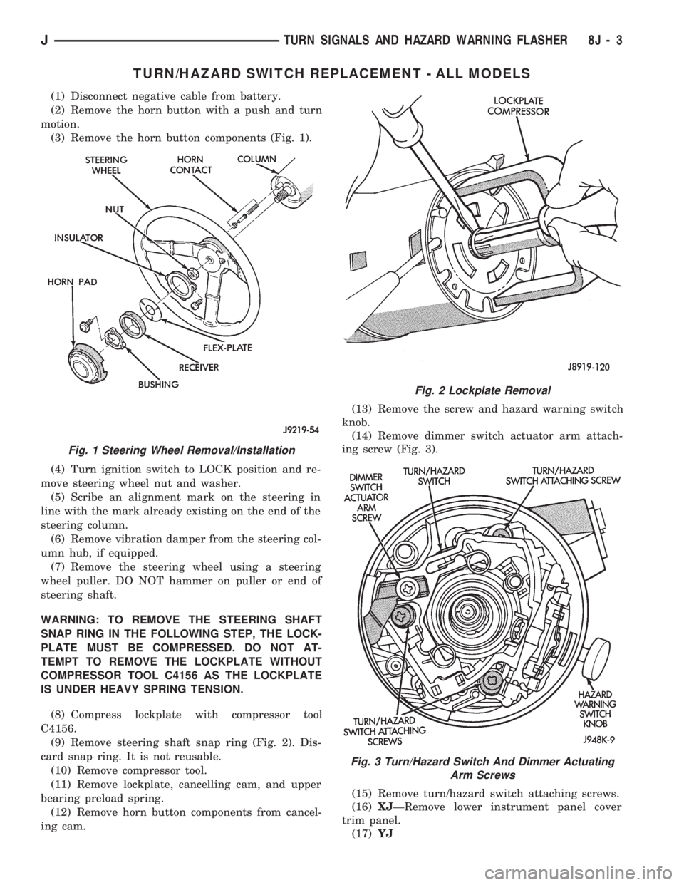
(3) Remove the horn button components (Fig. 1).
(4) Turn ignition switch to LOCK position and re-
move steering wheel nut and washer.
(5) Scribe an alignment mark on the steering in
line with the mark already existing on the end of the
steering column.
(6) Remove vibration damper from the steering col-
umn hub, if equipped.
(7) Remove the steering wheel using a steering
wheel puller. DO NOT hammer on puller or end of
steering shaft.
WARNING: TO REMOVE THE STEERING SHAFT
SNAP RING IN THE FOLLOWING STEP, THE LOCK-
PLATE MUST BE COMPRESSED. DO NOT AT-
TEMPT TO REMOVE THE LOCKPLATE WITHOUT
COMPRESSOR TOOL C4156 AS THE LOCKPLATE
IS UNDER HEAVY SPRING TENSION.
(8) Compress lockplate with compressor tool
C4156.
(9) Remove steering shaft snap ring (Fig. 2). Dis-
card snap ring. It is not reusable.
(10) Remove compressor tool.
(11) Remove lockplate, cancelling cam, and upper
bearing preload spring.
(12) Remove horn button components from cancel-
ing cam.(13) Remove the screw and hazard warning switch
knob.
(14) Remove dimmer switch actuator arm attach-
ing screw (Fig. 3).
(15) Remove turn/hazard switch attaching screws.
(16)XJÐRemove lower instrument panel cover
trim panel.
(17)YJ
Fig. 1 Steering Wheel Removal/Installation
Fig. 2 Lockplate Removal
Fig. 3 Turn/Hazard Switch And Dimmer Actuating
Arm Screws
JTURN SIGNALS AND HAZARD WARNING FLASHER 8J - 3
Page 405 of 1784

(a) Remove 6 housing screws (Fig. 4).
(b) Slide housing toward steering wheel.
(18) Remove cover under column.
(19) If vehicle is equipped with a column shift, re-
move PRNDL cable clip (Fig. 5).
(20) Remove 2 nuts holding steering column
bracket to brake sled (Fig. 6).
(21) Remove 4 bolts holding steering column
bracket to column.
(22) Loosen column brace mounting nut at drivers
side kick panel. This will allow column to drop.(23) Push turn/hazard connector up and out of
steering column connector (Fig. 7).
(24) Pry up locking tabs of steering column connec-
tor and remove connector from column bracket.
(25) Tape connector to wires as shown (Fig. 8).
(26) Remove plastic harness cover by pulling it up
and over the weld nuts then open and slide the cover
off the harness (Fig. 9).
Fig. 4 Instrument Housing Removal/InstallationÐYJ
Fig. 5 PRNDL Cable Clip Removal/Installation
Fig. 6 Lower Steering Column
Fig. 7 Turn/Hazard Switch And Steering Column
Connectors
8J - 4 TURN SIGNALS AND HAZARD WARNING FLASHERJ
Page 408 of 1784
WINDSHIELD WIPERS
CONTENTS
page page
WIPER CONTROL SWITCH REPLACEMENT . . 15
WIPER SWITCH TESTING................ 19XJ .................................... 1
YJ .................................... 8
XJ
INDEX
page page
Diagnosing Rear Wiper..................... 6
Diagnosing Rear Wiper Washer.............. 6
Diagnosing Windshield Washer (Intermittent)..... 5
Diagnosing Windshield Washer (Non-Intermittent) . 4
Diagnosing Windshield Wipers............... 11
Front Wipers/Washers...................... 1
Intermittent Wiper Module................... 5
Liftgate Wiper............................ 5Liftgate Wiper Switch Replacement............ 6
Rear Wiper/Washer Switch Testing............ 7
Torque Specifications XJ.................... 7
Washer Pump Replacement................. 6
Washer Pump ReplacementÐLeft Hand Drive.... 2
Washer Pump ReplacementÐRight Hand Drive . . 3
Windshield Wiper Motor.................... 2
FRONT WIPERS/WASHERS
GENERAL
Two-speed electric windshield wipers and electric
washers are standard equipment. An optional inter-
mittent wiper system provides a pause between wipe
cycles for use during conditions of very light precipi-
tation.
The windshield wipers can be operated with the
windshield wiper switch only when the ignition
switch is in the ON or ACCESSORY position. A cir-
cuit breaker located in the fuse block protects the cir-
cuitry of the wiper system.
WIPERS
The standard windshield wiper circuit contains
three components; wiper/washer switch, motor, and
front washer pump. Both standard and intermittent
circuits are the same, except that the intermittent
circuit requires a module and delay resistance in the
wiper switch. Both circuits receive battery feed from,
and are protected by a 5.5 amp circuit breaker.
In the standard wiper circuit, the switch connects
the motor directly to battery feed for low and high
speed operation. In the intermittent circuit, the
switch supplies battery feed to the intermittent wiper
module, which then supplies the motor. In the delay
position, the module is connected with the variable
resistor in the wiper switch. The value of the resis-tance is used by the module to charge a capacitor,
which triggers the amount of delay between wipes.
The wiper motor has an arrangement of brushes
providing the two wiper speeds. When the wipers are
turned off, the park switch maintains current to the
motor until the wipers reach the park position on the
windshield.
The park arm in the motor assembly is connected
to the park switch and is driven by the motor. When
the wiper switch is turned off, current flows through
the contact and the module to the motor until the
wipers reach the park position.
CAUTION: The wiper arms and blades must not be
moved manually from side to side or damage may
result.
WASHERS
With the washer switch ON, current flows through
the washer pump to ground. The front washer pump
runs as long as the driver holds the switch ON. On
standard wipers, the washer switch automatically
moves the wiper switch to LO when the washer is
turned on. On intermittent wipers, the wiper module
runs the wiper motor on LO. Turning the switch to
OFF stops the wipers.
If the washer knob is depressed while the wiper
switch is in the OFF position, the wiper control will
operate for approximately 3 wipes and automatically
turn OFF.
JWINDSHIELD WIPERS 8K - 1
Page 409 of 1784
WINDSHIELD WIPER MOTOR
REMOVAL
(1) Remove wiper arm assemblies by lifting blade
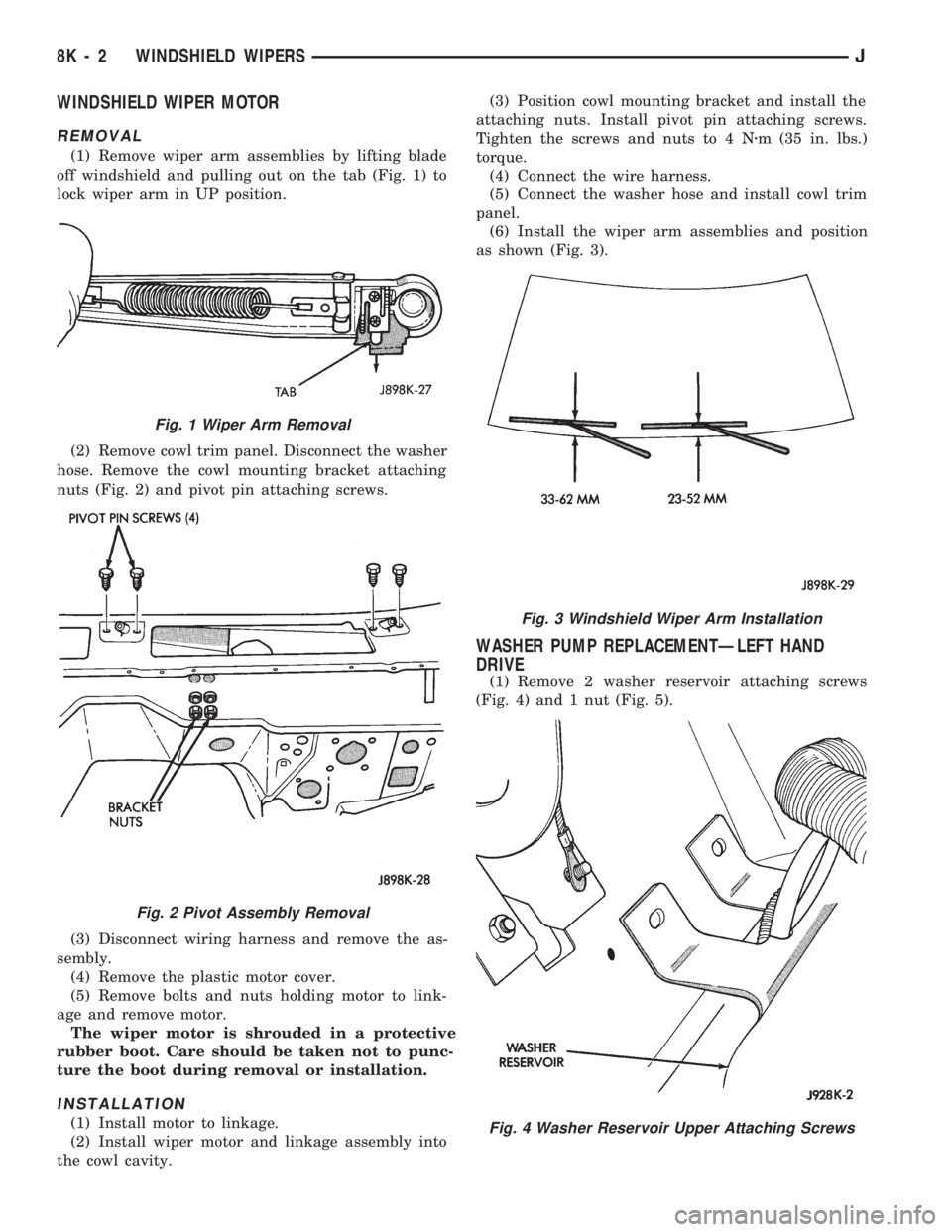
off windshield and pulling out on the tab (Fig. 1) to
lock wiper arm in UP position.
(2) Remove cowl trim panel. Disconnect the washer
hose. Remove the cowl mounting bracket attaching
nuts (Fig. 2) and pivot pin attaching screws.
(3) Disconnect wiring harness and remove the as-
sembly.
(4) Remove the plastic motor cover.
(5) Remove bolts and nuts holding motor to link-
age and remove motor.
The wiper motor is shrouded in a protective
rubber boot. Care should be taken not to punc-
ture the boot during removal or installation.
INSTALLATION
(1) Install motor to linkage.
(2) Install wiper motor and linkage assembly into
the cowl cavity.(3) Position cowl mounting bracket and install the
attaching nuts. Install pivot pin attaching screws.
Tighten the screws and nuts to 4 Nzm (35 in. lbs.)
torque.
(4) Connect the wire harness.
(5) Connect the washer hose and install cowl trim
panel.
(6) Install the wiper arm assemblies and position
as shown (Fig. 3).
WASHER PUMP REPLACEMENTÐLEFT HAND
DRIVE
(1) Remove 2 washer reservoir attaching screws
(Fig. 4) and 1 nut (Fig. 5).
Fig. 1 Wiper Arm Removal
Fig. 2 Pivot Assembly Removal
Fig. 3 Windshield Wiper Arm Installation
Fig. 4 Washer Reservoir Upper Attaching Screws
8K - 2 WINDSHIELD WIPERSJ
Page 410 of 1784
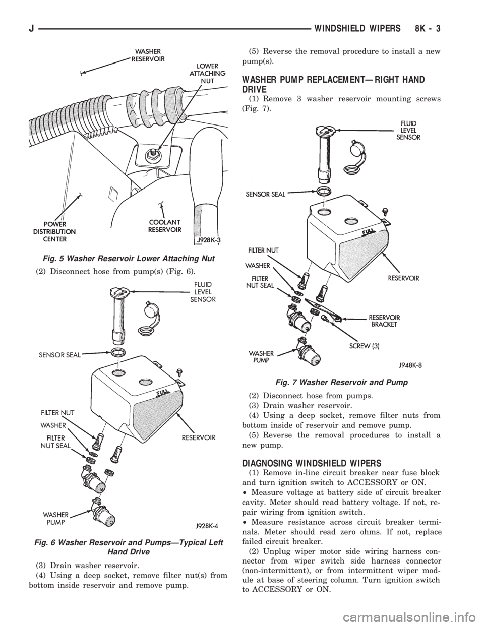
(2) Disconnect hose from pump(s) (Fig. 6).
(3) Drain washer reservoir.
(4) Using a deep socket, remove filter nut(s) from
bottom inside reservoir and remove pump.(5) Reverse the removal procedure to install a new
pump(s).
WASHER PUMP REPLACEMENTÐRIGHT HAND
DRIVE
(1) Remove 3 washer reservoir mounting screws
(Fig. 7).
(2) Disconnect hose from pumps.
(3) Drain washer reservoir.
(4) Using a deep socket, remove filter nuts from
bottom inside of reservoir and remove pump.
(5) Reverse the removal procedures to install a
new pump.
DIAGNOSING WINDSHIELD WIPERS
(1) Remove in-line circuit breaker near fuse block
and turn ignition switch to ACCESSORY or ON.
²Measure voltage at battery side of circuit breaker
cavity. Meter should read battery voltage. If not, re-
pair wiring from ignition switch.
²Measure resistance across circuit breaker termi-
nals. Meter should read zero ohms. If not, replace
failed circuit breaker.
(2) Unplug wiper motor side wiring harness con-
nector from wiper switch side harness connector
(non-intermittent), or from intermittent wiper mod-
ule at base of steering column. Turn ignition switch
to ACCESSORY or ON.
Fig. 5 Washer Reservoir Lower Attaching Nut
Fig. 6 Washer Reservoir and PumpsÐTypical Left
Hand Drive
Fig. 7 Washer Reservoir and Pump
JWINDSHIELD WIPERS 8K - 3
Page 415 of 1784
YJ
INDEX
page page
Diagnosing Windshield Wipers............... 11
Diagnosing Intermittent Windshield Washer..... 12
Diagnosing Non-Intermittent Windshield Washer . 12
Diagnosing Rear Wiper/Washer.............. 14
Front Wiper Arm and Pivot Assembly Replacement . 9
Front Wiper Arm Replacement............... 8
Front Wiper Blade Replacement.............. 8
Front Wiper Motor........................ 10Front Wipers/Washers General Information...... 8
Rear Washer Pump Replacement............ 13
Rear Wiper Arm Replacement............... 12
Rear Wiper Motor Replacement.............. 13
Rear Wiper Switch Replacement............. 13
Rear Wiper/Washer Switch Testing........... 14
Washer Nozzle Replacement................ 13
Washer Pump Replacement................ 11
FRONT WIPERS/WASHERS GENERAL
INFORMATION
The non-intermittent windshield wiper circuit con-
tains three components; control switch, motor and
washer pump. The intermittent circuit contains the
same components and a wiper module that provides
the delay function. Both circuits receive battery feed
from and are protected by a 5.3 amp circuit breaker.
In the non-intermittent wiper circuit, the switch
connects the motor directly to ignition feed for low
and high speed operation. In the intermittent circuit,
the switch supplies ignition feed to the delay module,
which then supplies the motor. In the delay position,
the module is connected with the variable resistor in
the wiper switch. The value of the resistance is used
by the solid state module to charge a capacitor,
which triggers the amount of delay between wipes.
The wiper motor has an arrangement of brushes
providing the two wiper speeds. When the wipers are
turned off, the park switch maintains current to the
motor until the wipers reach the park position on the
windshield.
The washer pump receives ignition feed either di-
rectly from the wiper switch or from the intermittent
module. In either case the electric motor will drive
the washer pump.
The wiper motor is mounted on the lower left cor-
ner of the windshield.
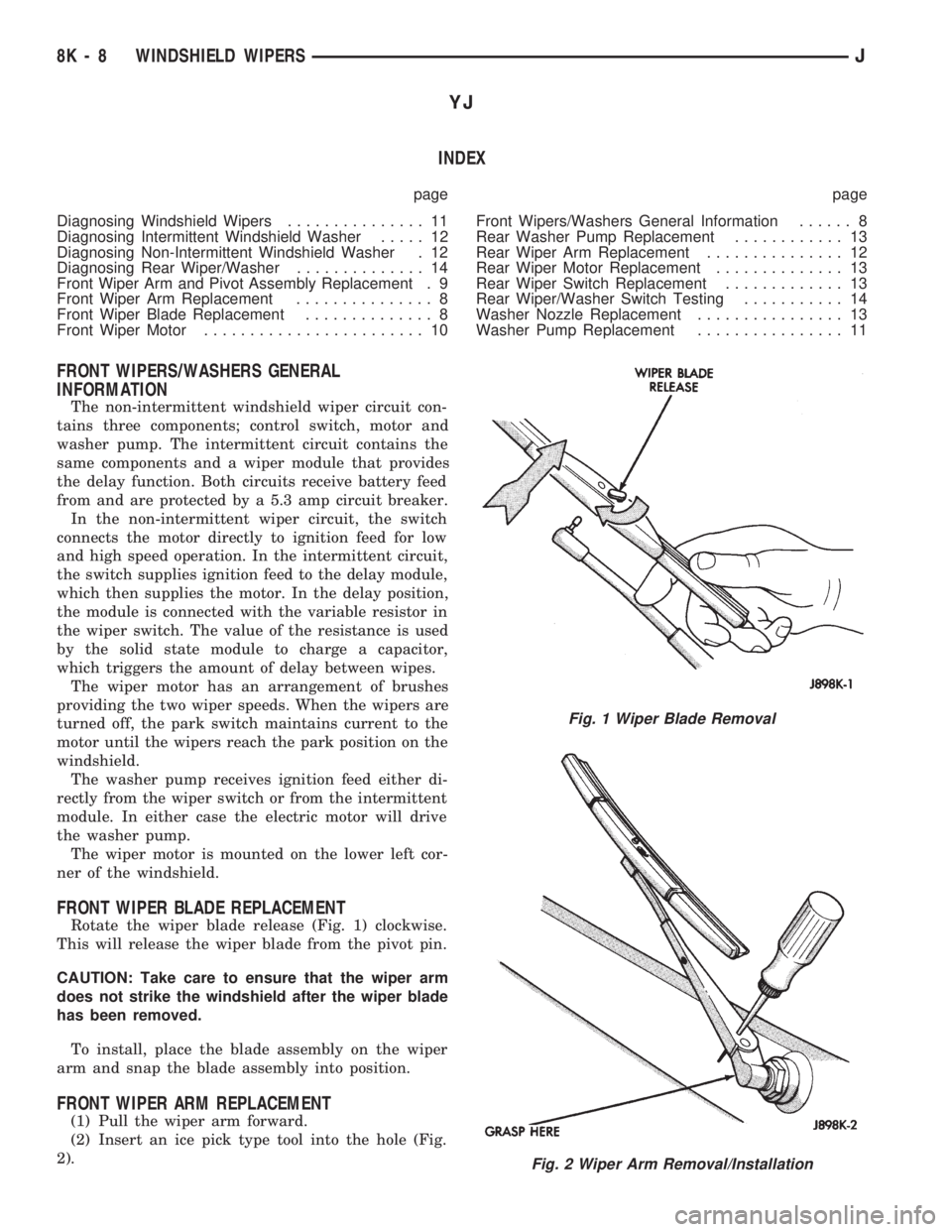
FRONT WIPER BLADE REPLACEMENT
Rotate the wiper blade release (Fig. 1) clockwise.
This will release the wiper blade from the pivot pin.
CAUTION: Take care to ensure that the wiper arm
does not strike the windshield after the wiper blade
has been removed.
To install, place the blade assembly on the wiper
arm and snap the blade assembly into position.
FRONT WIPER ARM REPLACEMENT
(1) Pull the wiper arm forward.
(2) Insert an ice pick type tool into the hole (Fig.
2).
Fig. 1 Wiper Blade Removal
Fig. 2 Wiper Arm Removal/Installation
8K - 8 WINDSHIELD WIPERSJ