1994 JEEP CHEROKEE lamps
[x] Cancel search: lampsPage 899 of 1784
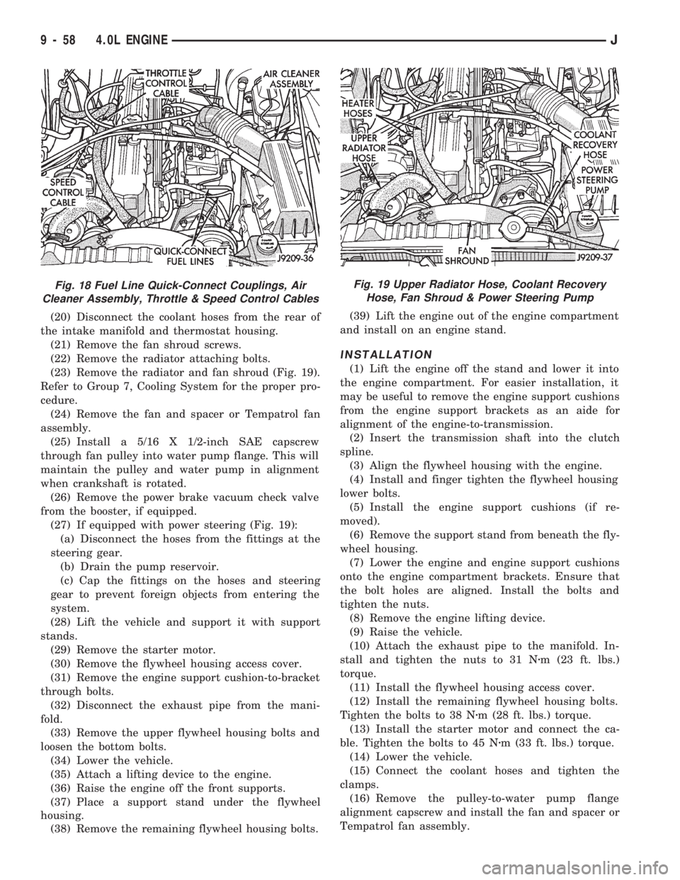
(20) Disconnect the coolant hoses from the rear of
the intake manifold and thermostat housing.
(21) Remove the fan shroud screws.
(22) Remove the radiator attaching bolts.
(23) Remove the radiator and fan shroud (Fig. 19).
Refer to Group 7, Cooling System for the proper pro-
cedure.
(24) Remove the fan and spacer or Tempatrol fan
assembly.
(25) Install a 5/16 X 1/2-inch SAE capscrew
through fan pulley into water pump flange. This will
maintain the pulley and water pump in alignment
when crankshaft is rotated.
(26) Remove the power brake vacuum check valve
from the booster, if equipped.
(27) If equipped with power steering (Fig. 19):
(a) Disconnect the hoses from the fittings at the
steering gear.
(b) Drain the pump reservoir.
(c) Cap the fittings on the hoses and steering
gear to prevent foreign objects from entering the
system.
(28) Lift the vehicle and support it with support
stands.
(29) Remove the starter motor.
(30) Remove the flywheel housing access cover.
(31) Remove the engine support cushion-to-bracket
through bolts.
(32) Disconnect the exhaust pipe from the mani-
fold.
(33) Remove the upper flywheel housing bolts and
loosen the bottom bolts.
(34) Lower the vehicle.
(35) Attach a lifting device to the engine.
(36) Raise the engine off the front supports.
(37) Place a support stand under the flywheel
housing.
(38) Remove the remaining flywheel housing bolts.(39) Lift the engine out of the engine compartment
and install on an engine stand.
INSTALLATION
(1) Lift the engine off the stand and lower it into
the engine compartment. For easier installation, it
may be useful to remove the engine support cushions
from the engine support brackets as an aide for
alignment of the engine-to-transmission.
(2) Insert the transmission shaft into the clutch
spline.
(3) Align the flywheel housing with the engine.
(4) Install and finger tighten the flywheel housing
lower bolts.
(5) Install the engine support cushions (if re-
moved).
(6) Remove the support stand from beneath the fly-
wheel housing.
(7) Lower the engine and engine support cushions
onto the engine compartment brackets. Ensure that
the bolt holes are aligned. Install the bolts and
tighten the nuts.
(8) Remove the engine lifting device.
(9) Raise the vehicle.
(10) Attach the exhaust pipe to the manifold. In-
stall and tighten the nuts to 31 Nzm (23 ft. lbs.)
torque.
(11) Install the flywheel housing access cover.
(12) Install the remaining flywheel housing bolts.
Tighten the bolts to 38 Nzm (28 ft. lbs.) torque.
(13) Install the starter motor and connect the ca-
ble. Tighten the bolts to 45 Nzm (33 ft. lbs.) torque.
(14) Lower the vehicle.
(15) Connect the coolant hoses and tighten the
clamps.
(16) Remove the pulley-to-water pump flange
alignment capscrew and install the fan and spacer or
Tempatrol fan assembly.
Fig. 18 Fuel Line Quick-Connect Couplings, Air
Cleaner Assembly, Throttle & Speed Control CablesFig. 19 Upper Radiator Hose, Coolant Recovery
Hose, Fan Shroud & Power Steering Pump
9 - 58 4.0L ENGINEJ
Page 937 of 1784
red. Remove the exhaust tailpipe/muffler clamp and
twist the exhaust tailpipe out of the muffler.
INSTALLATION
(1) Install the muffler onto the catalytic converter.
Install the clamp and tighten the nuts finger tight.
(2) Install the exhaust tailpipe into the rear of the
muffler.
(3) Install the exhaust tailpipe/muffler assembly
on the rear exhaust tailpipe hanger. Make sure that
the exhaust tailpipe has sufficient clearance from the
floor pan.
(4) Install the remaining clamps and the front ex-
haust tailpipe hanger.
(5) Tighten the nuts on the muffler-to-catalytic
converter clamp to 61 Nzm (45 ft. lbs.) torque (Fig.
6). Tighten the nuts on the rear exhaust tailpipe
clamp to 14 Nzm (10 ft. lbs.) torque (Fig. 7).
(6) Lower the vehicle.
(7) Start the engine and inspect for exhaust leaks
and exhaust system contact with the body panels.
Adjust the alignment, if needed.
MUFFLER AND EXHAUST TAILPIPEÐYJ VEHICLES
All original equipment exhaust systems are manu-
factured with the exhaust tailpipe welded to the muf-
fler. Service replacement mufflers and exhaust
tailpipes are clamped together.
WARNING: IF TORCHES ARE USED WHEN WORK-
ING ON THE EXHAUST SYSTEM, DO NOT ALLOW
THE FLAME NEAR THE FUEL LINES.
REMOVAL
(1) Raise the vehicle and support the rear of the
vehicle by the side rails and allow the axle to hang
free.
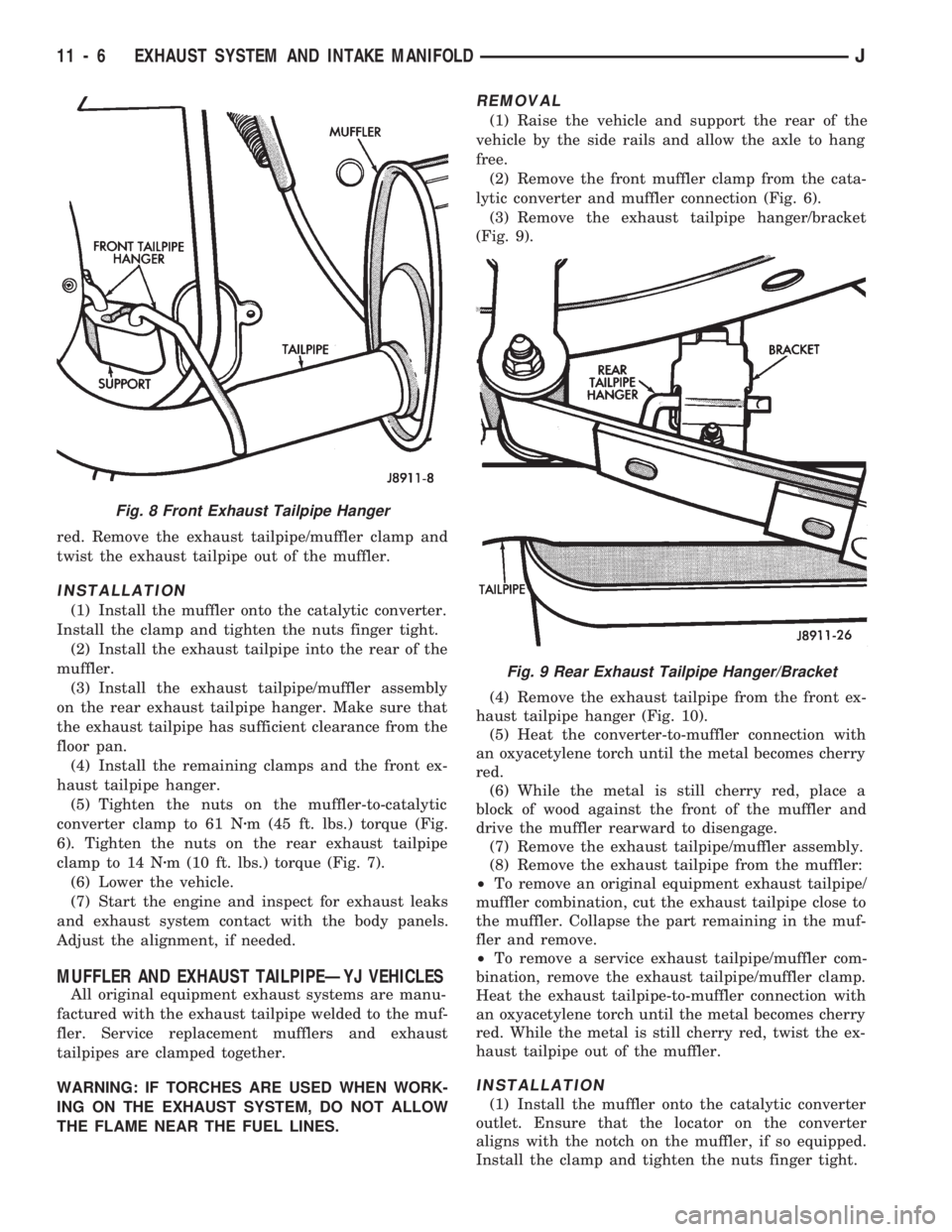
(2) Remove the front muffler clamp from the cata-
lytic converter and muffler connection (Fig. 6).
(3) Remove the exhaust tailpipe hanger/bracket
(Fig. 9).
(4) Remove the exhaust tailpipe from the front ex-
haust tailpipe hanger (Fig. 10).
(5) Heat the converter-to-muffler connection with
an oxyacetylene torch until the metal becomes cherry
red.
(6) While the metal is still cherry red, place a
block of wood against the front of the muffler and
drive the muffler rearward to disengage.
(7) Remove the exhaust tailpipe/muffler assembly.
(8) Remove the exhaust tailpipe from the muffler:
²To remove an original equipment exhaust tailpipe/
muffler combination, cut the exhaust tailpipe close to
the muffler. Collapse the part remaining in the muf-
fler and remove.
²To remove a service exhaust tailpipe/muffler com-
bination, remove the exhaust tailpipe/muffler clamp.
Heat the exhaust tailpipe-to-muffler connection with
an oxyacetylene torch until the metal becomes cherry
red. While the metal is still cherry red, twist the ex-
haust tailpipe out of the muffler.
INSTALLATION
(1) Install the muffler onto the catalytic converter
outlet. Ensure that the locator on the converter
aligns with the notch on the muffler, if so equipped.
Install the clamp and tighten the nuts finger tight.
Fig. 8 Front Exhaust Tailpipe Hanger
Fig. 9 Rear Exhaust Tailpipe Hanger/Bracket
11 - 6 EXHAUST SYSTEM AND INTAKE MANIFOLDJ
Page 938 of 1784
(2) Install the exhaust tailpipe into the muffler
outlet. Ensure that the locator on the exhaust
tailpipe aligns with the notch on the muffler, if so
equipped. Install the clamp and tighten the nuts fin-
ger tight.
(3) Install the front exhaust tailpipe supports and
the rear exhaust tailpipe hanger. Ensure that the ex-
haust tailpipe has sufficient clearance from the floor
pan and shields.
(4) Tighten the nuts on the muffler-to-catalytic
converter and the muffler-to-exhaust tailpipe clamps
to 61 Nzm (45 ft. lbs.) torque.
(5) Lower the vehicle.
(6) Start the engine and inspect for exhaust leaks
and contact with the body panels and shields.
ENGINE EXHAUST MANIFOLDÐ2.5L ENGINE
REMOVAL
(1) Disconnect the battery negative cable.
(2) Remove all components attached to the intake
manifold.
(3) Raise the vehicle.
(4) Disconnect the exhaust pipe from the engine
exhaust manifold.
(5) Lower the vehicle.
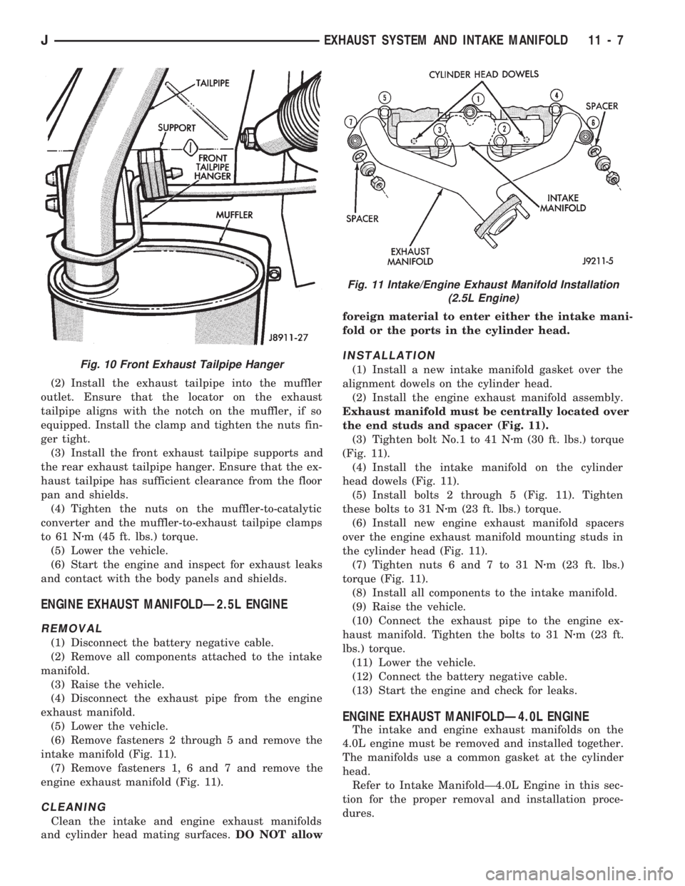
(6) Remove fasteners 2 through 5 and remove the
intake manifold (Fig. 11).
(7) Remove fasteners 1, 6 and 7 and remove the
engine exhaust manifold (Fig. 11).
CLEANING
Clean the intake and engine exhaust manifolds
and cylinder head mating surfaces.DO NOT allowforeign material to enter either the intake mani-
fold or the ports in the cylinder head.
INSTALLATION
(1) Install a new intake manifold gasket over the
alignment dowels on the cylinder head.
(2) Install the engine exhaust manifold assembly.
Exhaust manifold must be centrally located over
the end studs and spacer (Fig. 11).
(3) Tighten bolt No.1 to 41 Nzm (30 ft. lbs.) torque
(Fig. 11).
(4) Install the intake manifold on the cylinder
head dowels (Fig. 11).
(5) Install bolts 2 through 5 (Fig. 11). Tighten
these bolts to 31 Nzm (23 ft. lbs.) torque.
(6) Install new engine exhaust manifold spacers
over the engine exhaust manifold mounting studs in
the cylinder head (Fig. 11).
(7) Tighten nuts 6 and 7 to 31 Nzm (23 ft. lbs.)
torque (Fig. 11).
(8) Install all components to the intake manifold.
(9) Raise the vehicle.
(10) Connect the exhaust pipe to the engine ex-
haust manifold. Tighten the bolts to 31 Nzm (23 ft.
lbs.) torque.
(11) Lower the vehicle.
(12) Connect the battery negative cable.
(13) Start the engine and check for leaks.
ENGINE EXHAUST MANIFOLDÐ4.0L ENGINE
The intake and engine exhaust manifolds on the
4.0L engine must be removed and installed together.
The manifolds use a common gasket at the cylinder
head.
Refer to Intake ManifoldÐ4.0L Engine in this sec-
tion for the proper removal and installation proce-
dures.
Fig. 10 Front Exhaust Tailpipe Hanger
Fig. 11 Intake/Engine Exhaust Manifold Installation
(2.5L Engine)
JEXHAUST SYSTEM AND INTAKE MANIFOLD 11 - 7
Page 945 of 1784
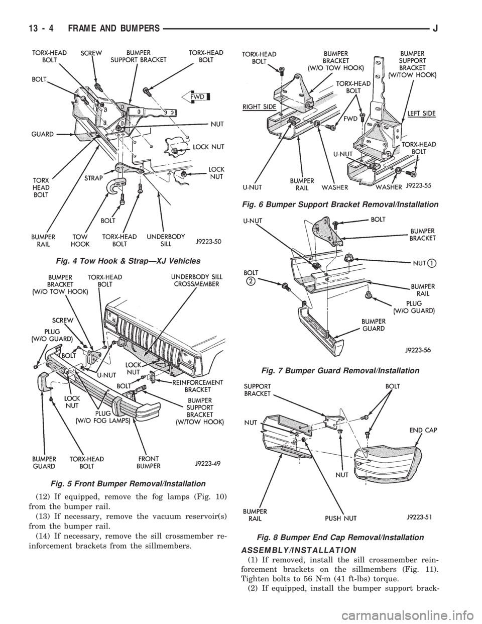
(12) If equipped, remove the fog lamps (Fig. 10)
from the bumper rail.
(13) If necessary, remove the vacuum reservoir(s)
from the bumper rail.
(14) If necessary, remove the sill crossmember re-
inforcement brackets from the sillmembers.
ASSEMBLY/INSTALLATION
(1) If removed, install the sill crossmember rein-
forcement brackets on the sillmembers (Fig. 11).
Tighten bolts to 56 Nzm (41 ft-lbs) torque.
(2) If equipped, install the bumper support brack-
Fig. 4 Tow Hook & StrapÐXJ Vehicles
Fig. 5 Front Bumper Removal/Installation
Fig. 6 Bumper Support Bracket Removal/Installation
Fig. 7 Bumper Guard Removal/Installation
Fig. 8 Bumper End Cap Removal/Installation
13 - 4 FRAME AND BUMPERSJ
Page 946 of 1784
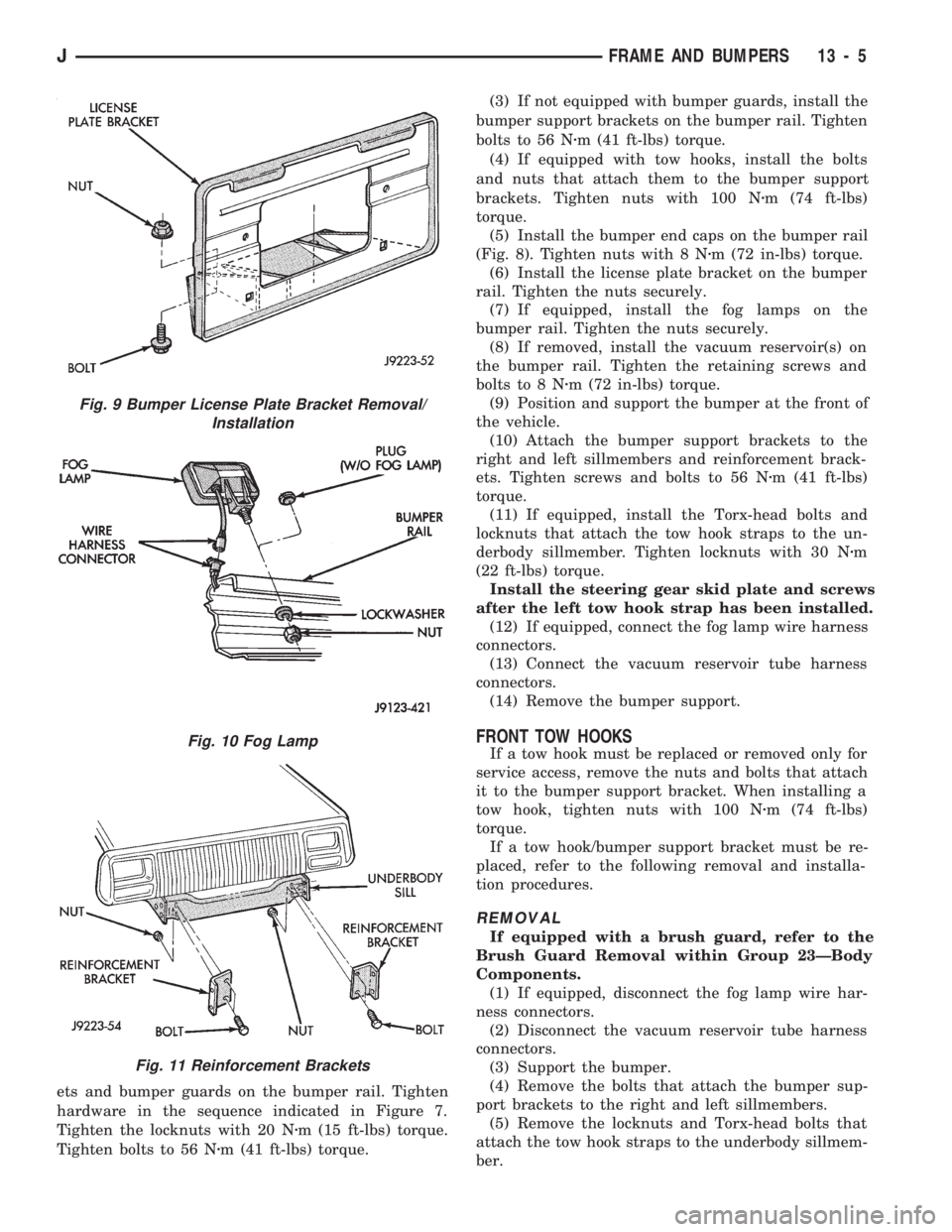
ets and bumper guards on the bumper rail. Tighten
hardware in the sequence indicated in Figure 7.
Tighten the locknuts with 20 Nzm (15 ft-lbs) torque.
Tighten bolts to 56 Nzm (41 ft-lbs) torque.(3) If not equipped with bumper guards, install the
bumper support brackets on the bumper rail. Tighten
bolts to 56 Nzm (41 ft-lbs) torque.
(4) If equipped with tow hooks, install the bolts
and nuts that attach them to the bumper support
brackets. Tighten nuts with 100 Nzm (74 ft-lbs)
torque.
(5) Install the bumper end caps on the bumper rail
(Fig. 8). Tighten nuts with 8 Nzm (72 in-lbs) torque.
(6) Install the license plate bracket on the bumper
rail. Tighten the nuts securely.
(7) If equipped, install the fog lamps on the
bumper rail. Tighten the nuts securely.
(8) If removed, install the vacuum reservoir(s) on
the bumper rail. Tighten the retaining screws and
bolts to 8 Nzm (72 in-lbs) torque.
(9) Position and support the bumper at the front of
the vehicle.
(10) Attach the bumper support brackets to the
right and left sillmembers and reinforcement brack-
ets. Tighten screws and bolts to 56 Nzm (41 ft-lbs)
torque.
(11) If equipped, install the Torx-head bolts and
locknuts that attach the tow hook straps to the un-
derbody sillmember. Tighten locknuts with 30 Nzm
(22 ft-lbs) torque.
Install the steering gear skid plate and screws
after the left tow hook strap has been installed.
(12) If equipped, connect the fog lamp wire harness
connectors.
(13) Connect the vacuum reservoir tube harness
connectors.
(14) Remove the bumper support.
FRONT TOW HOOKS
If a tow hook must be replaced or removed only for
service access, remove the nuts and bolts that attach
it to the bumper support bracket. When installing a
tow hook, tighten nuts with 100 Nzm (74 ft-lbs)
torque.
If a tow hook/bumper support bracket must be re-
placed, refer to the following removal and installa-
tion procedures.
REMOVAL
If equipped with a brush guard, refer to the
Brush Guard Removal within Group 23ÐBody
Components.
(1) If equipped, disconnect the fog lamp wire har-
ness connectors.
(2) Disconnect the vacuum reservoir tube harness
connectors.
(3) Support the bumper.
(4) Remove the bolts that attach the bumper sup-
port brackets to the right and left sillmembers.
(5) Remove the locknuts and Torx-head bolts that
attach the tow hook straps to the underbody sillmem-
ber.
Fig. 9 Bumper License Plate Bracket Removal/
Installation
Fig. 10 Fog Lamp
Fig. 11 Reinforcement Brackets
JFRAME AND BUMPERS 13 - 5
Page 955 of 1784

YJ BUMPERS AND FRAME ATTACHED COMPONENTS
INDEX
page page
Generator Splash Shield................... 14
Body.................................. 18
Engine Front Support Cushion............... 15
Frame Crossmember Cover................. 14
Front Bumper........................... 14
Fuel and Brake Fluid Tube Retainer Clip....... 16
Fuel Filter Shield and Bracket............... 17
Fuel Tank Skid Plate...................... 16Muffler and Tailpipe Heat Shields............ 17
Muffler/Tailpipe Hanger Bracket.............. 16
Rear Bumper............................ 18
Rear Jounce Bumper..................... 18
Service Information....................... 14
Tow Hooks............................. 14
Transfer Case Skid Plate.................. 15
SERVICE INFORMATION
In some cases, components in the following proce-
dures either support, or are hidden by other compo-
nents.
FRONT BUMPER
The YJ front bumper is a one-piece rail (Fig. 1). A
front crossmember cover (Fig. 1) is also installed on
all YJ vehicles.
BUMPER REMOVAL
(1) Disconnect and remove the fog lamps, if
equipped.
(2) Remove the nuts and bolts that retain the
bumper extensions to the bumper rail and remove
the extensions.
(3) Remove the nuts and bolts that attach the
bumper rail/tow hooks to the frame rails.(4) Remove the bumper rail from the frame rails.
BUMPER INSTALLATION
(1) Position the front bumper on the frame rails.
(2) Install the bolts and attach the front bumper
rail (and tow hooks, if equipped) to the frame rails.
(3) Tighten the bolts to 102 Nzm (75 ft-lbs) torque.
(4) Position the bumper extensions on the bumper
rail and install the retaining bolts.
(5) Tighten the bolts to 104 Nzm (77 ft-lbs) torque.
(6) Install the fog lamps, if equipped.
FRAME CROSSMEMBER COVER
REMOVAL
(1) Remove the screws that attach the crossmem-
ber cover and support to the frame rails.
(2) Remove the crossmember cover and support
from the frame rails.
INSTALLATION
(1) Position the support and crossmember cover on
the frame rails.
(2) Install the attaching screws.
(3) Tighten the screws to 8 Nzm (72 in-lbs) torque.
TOW HOOKS
REMOVAL
(1) Remove the two bolts that attach the tow hook
to the bumper rail and to the frame rail.
(2) Remove the tow hook.
INSTALLATION
(1) Position the tow hook on the bumper rail and
frame rail.
(2) Install the attaching bolts.
(3) Tighten the bolts to 102 Nzm (75 ft-lbs) torque.
GENERATOR SPLASH SHIELD
REMOVAL
(1) Remove the shield retaining nut and washer
(Fig. 2) from the engine oil pan stud (2.5L engines
only).
Fig. 1 Front Bumper Rail, Crossmember Cover &
Tow Hooks
13 - 14 FRAME AND BUMPERSJ
Page 961 of 1784
(1) Disconnect the battery negative cable.
(2) Disconnect all wire harness connectors that
connect body wire harnesses to the frame wire har-
nesses.
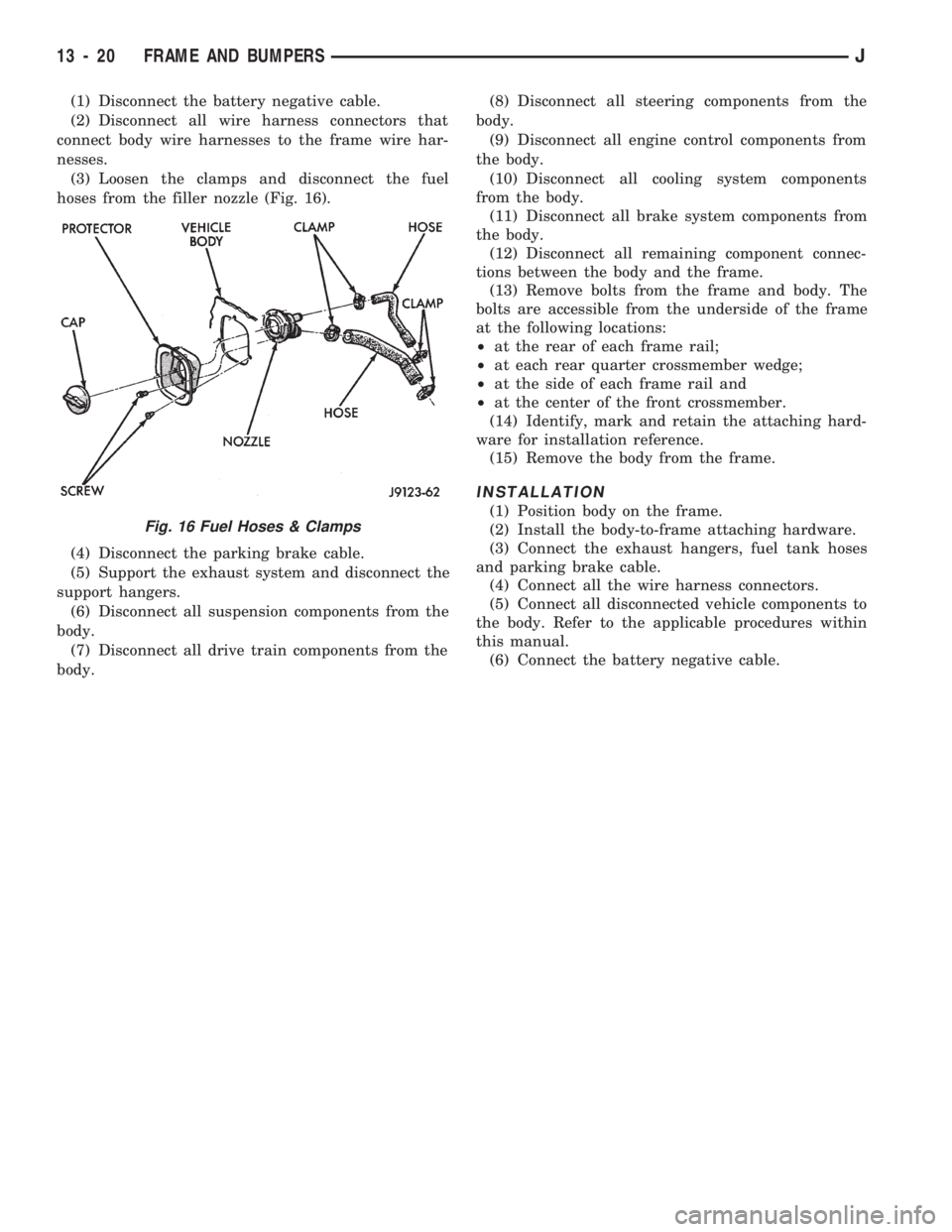
(3) Loosen the clamps and disconnect the fuel
hoses from the filler nozzle (Fig. 16).
(4) Disconnect the parking brake cable.
(5) Support the exhaust system and disconnect the
support hangers.
(6) Disconnect all suspension components from the
body.
(7) Disconnect all drive train components from the
body.(8) Disconnect all steering components from the
body.
(9) Disconnect all engine control components from
the body.
(10) Disconnect all cooling system components
from the body.
(11) Disconnect all brake system components from
the body.
(12) Disconnect all remaining component connec-
tions between the body and the frame.
(13) Remove bolts from the frame and body. The
bolts are accessible from the underside of the frame
at the following locations:
²at the rear of each frame rail;
²at each rear quarter crossmember wedge;
²at the side of each frame rail and
²at the center of the front crossmember.
(14) Identify, mark and retain the attaching hard-
ware for installation reference.
(15) Remove the body from the frame.
INSTALLATION
(1) Position body on the frame.
(2) Install the body-to-frame attaching hardware.
(3) Connect the exhaust hangers, fuel tank hoses
and parking brake cable.
(4) Connect all the wire harness connectors.
(5) Connect all disconnected vehicle components to
the body. Refer to the applicable procedures within
this manual.
(6) Connect the battery negative cable.
Fig. 16 Fuel Hoses & Clamps
13 - 20 FRAME AND BUMPERSJ
Page 963 of 1784
line. You may encounter fuels containing 3 percent
or more methanol along with other alcohols called co-
solvents.
Problems that are the result of using methanol/gas-
oline blends are not the responsibility of Chrysler
Corporation. They may not be covered by the vehicle
warranty.
MTBE/ETBE
Gasoline and MTBE (Methyl Tertiary Butyl Ether)
blends are a mixture of unleaded gasoline and up to
15 percent MTBE. Gasoline and ETBE (Ethyl Ter-
tiary Butyl Ether) are blends of gasoline and up to
17 percent ETBE. Gasoline blended with MTBE or
ETBE may be used in your vehicle.CLEAN AIR GASOLINE
Many gasolines are now being blended that con-
tribute to cleaner air, especially in those areas of the
country where air pollution levels are high. These
new blends provide a cleaner burning fuel and some
are referred to asReformulated Gasoline.
In areas of the country where carbon monoxide lev-
els are high, gasolines are being treated with oxy-
genated materials such as MTBE, ETBE and
ethanol.
Chrysler Corporation supports these efforts toward
cleaner air and recommends that you use these gas-
olines as they become available.
FUEL DELIVERY SYSTEM
INDEX
page page
Fuel Filter............................... 8
Fuel Pressure Leak Down Test............... 7
Fuel Pressure Release Procedure............. 5
Fuel Pump Capacity Test................... 7
Fuel Pump Electrical Control................. 5Fuel Pump Module........................ 2
Fuel System Pressure Test.................. 5
Fuel Tubes/Lines/Hoses and Clamps........... 9
Quick-Connect Fittings..................... 9
FUEL PUMP MODULE
The fuel pump module is installed in the top of the
fuel tank. The fuel pump module contains the follow-
ing components:
²Electric fuel pump
²Fuel pump reservoir
²In-tank fuel filter
²Fuel gauge sending unit
²Fuel supply and return tube connections
The fuel pump used on all vehicles is a gear/rotor
type pump. It is driven by a permanent magnet 12
volt electric motor that is immersed in the fuel tank.
The electrical pump is integral with the fuel sender
unit. The pump/sender assembly is installed inside
the fuel tank.
The fuel pump has a check valve at the outlet end
that consists of a ball held against a seat by force ap-
plied from a spring. When the pump is operating,
fuel pressure overcomes spring pressure and forces
the ball off its seat, allowing fuel to flow. When the
pump is not operating, spring pressure forces the ball
back against the seat preventing fuel backflow
through the pump.
Fuel system pressure is maintained at approxi-
mately 214 kPa (31 psi). This is when the pump is
operating and vacuum is supplied to the fuel pres-
sure regulator. If vacuum is not supplied to the pres-
sure regulator, fuel pressure will be approximately
55-69 kPa (8-10 psi) higher. This may be due to a
broken or clogged vacuum line. When the fuel pumpis not operating, system fuel pressure of 131-269 kPa
(19-39 psi) is maintained. This is done by the fuel
pump outlet check valve and the vacuum assisted
fuel pressure regulator.
REMOVALÐXJ MODELS
The fuel pump/gauge sender unit assembly can be
removed from the fuel tank without removing the
tank from the vehicle.
WARNING: THE FUEL SYSTEM IS UNDER A CON-
STANT PRESSURE (EVEN WITH THE ENGINE OFF).
BEFORE SERVICING THE FUEL PUMP MODULE,
THE FUEL SYSTEM PRESSURE MUST BE RE-
LEASED. REFER TO THE FUEL PRESSURE RE-
LEASE PROCEDURE IN THIS GROUP.
WARNING: EXTINGUISH ALL TOBACCO SMOKING
PRODUCTS BEFORE SERVICING THE FUEL SYS-
TEM. KEEP OPEN FLAME AWAY FROM FUEL SYS-
TEM COMPONENTS.
(1) Remove fuel filler cap. Perform the Fuel Pres-
sure Release Procedure as outlined in this group.
(2) Disconnect negative battery cable.
(3) Using an approved portable gasoline siphon/
storage tank, drain fuel tank until fuel level is below
one quarter (1/4) full.
(4) Raise and support vehicle.
14 - 2 FUEL SYSTEMJ