1994 JEEP CHEROKEE lamps
[x] Cancel search: lampsPage 1458 of 1784
EXTERIOR COMPONENTS
BRUSH GUARD
REMOVAL
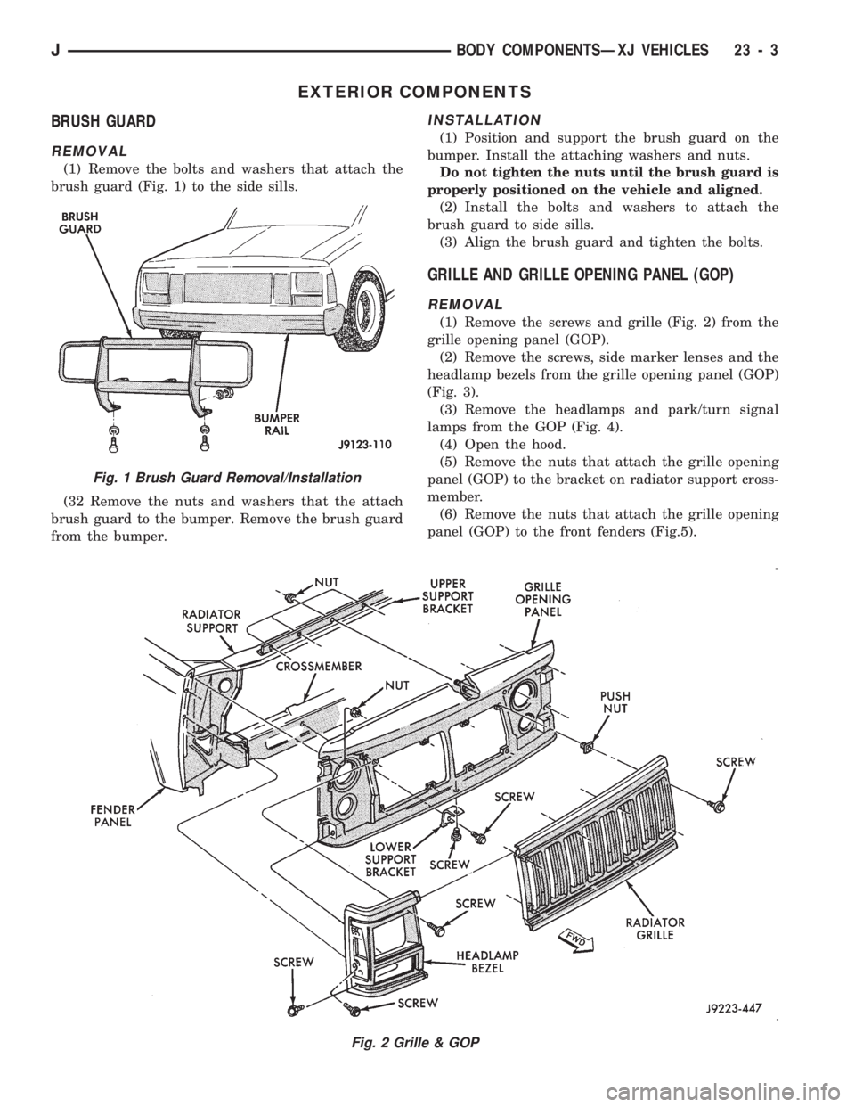
(1) Remove the bolts and washers that attach the
brush guard (Fig. 1) to the side sills.
(32 Remove the nuts and washers that the attach
brush guard to the bumper. Remove the brush guard
from the bumper.
INSTALLATION
(1) Position and support the brush guard on the
bumper. Install the attaching washers and nuts.
Do not tighten the nuts until the brush guard is
properly positioned on the vehicle and aligned.
(2) Install the bolts and washers to attach the
brush guard to side sills.
(3) Align the brush guard and tighten the bolts.
GRILLE AND GRILLE OPENING PANEL (GOP)
REMOVAL
(1) Remove the screws and grille (Fig. 2) from the
grille opening panel (GOP).
(2) Remove the screws, side marker lenses and the
headlamp bezels from the grille opening panel (GOP)
(Fig. 3).
(3) Remove the headlamps and park/turn signal
lamps from the GOP (Fig. 4).
(4) Open the hood.
(5) Remove the nuts that attach the grille opening
panel (GOP) to the bracket on radiator support cross-
member.
(6) Remove the nuts that attach the grille opening
panel (GOP) to the front fenders (Fig.5).
Fig. 2 Grille & GOP
Fig. 1 Brush Guard Removal/Installation
JBODY COMPONENTSÐXJ VEHICLES 23 - 3
Page 1460 of 1784
INSTALLATION
(1) Place the grille opening panel (GOP) on bumper
and connect all front lamp wire harness connectors.
(2) Position the grille opening panel (GOP) on the
vehicle and install the side and upper nuts. Tighten
nuts to 7 Nzm (58 in-lbs) torque.
(3) Install the screw to attach grille opening panel
(GOP) to the crossmember support bracket. Tighten
the screw to 1 Nzm (11 in-lbs) torque.
(4) Install headlamps and park/turn signal lamps
in GOP.(5) Install the headlamp bezels on the GOP.
Tighten the screws to 1 Nzm (13 in-lbs) torque.
(6) Install the side marker lenses and screws on
the grille opening panel (GOP). Tighten the screws to
1Nzm (13 in-lbs) torque.
(7) Install the grille on the GOP. Tighten screws to
1Nzm (13 in-lbs) torque.
(8) Adjust the headlamp aim, if necessary. Refer to
the headlamp beam adjustment procedure within
Group 8L.
RADIATOR SUPPORT CROSSMEMBER
REMOVAL
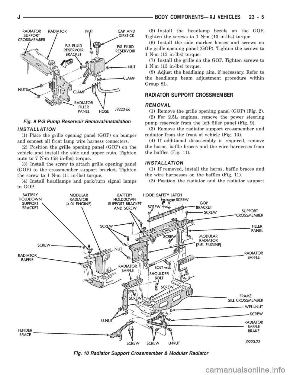
(1) Remove the grille opening panel (GOP) (Fig. 2).
(2) For 2.5L engines, remove the power steering
pump reservoir from the left filler panel (Fig. 9).
(3) Remove the radiator support crossmember and
radiator from the front of vehicle (Fig. 10).
(4) If additional disassembly is required, remove
the horns, baffle braces and the wire harnesses from
the baffles (Fig. 11).
INSTALLATION
(1) If removed, install the horns, baffle braces and
the wire harnesses on the baffles (Fig. 11).
(2) Position the radiator and the radiator support
Fig. 9 P/S Pump Reservoir Removal/Installation
Fig. 10 Radiator Support Crossmember & Modular Radiator
JBODY COMPONENTSÐXJ VEHICLES 23 - 5
Page 1472 of 1784
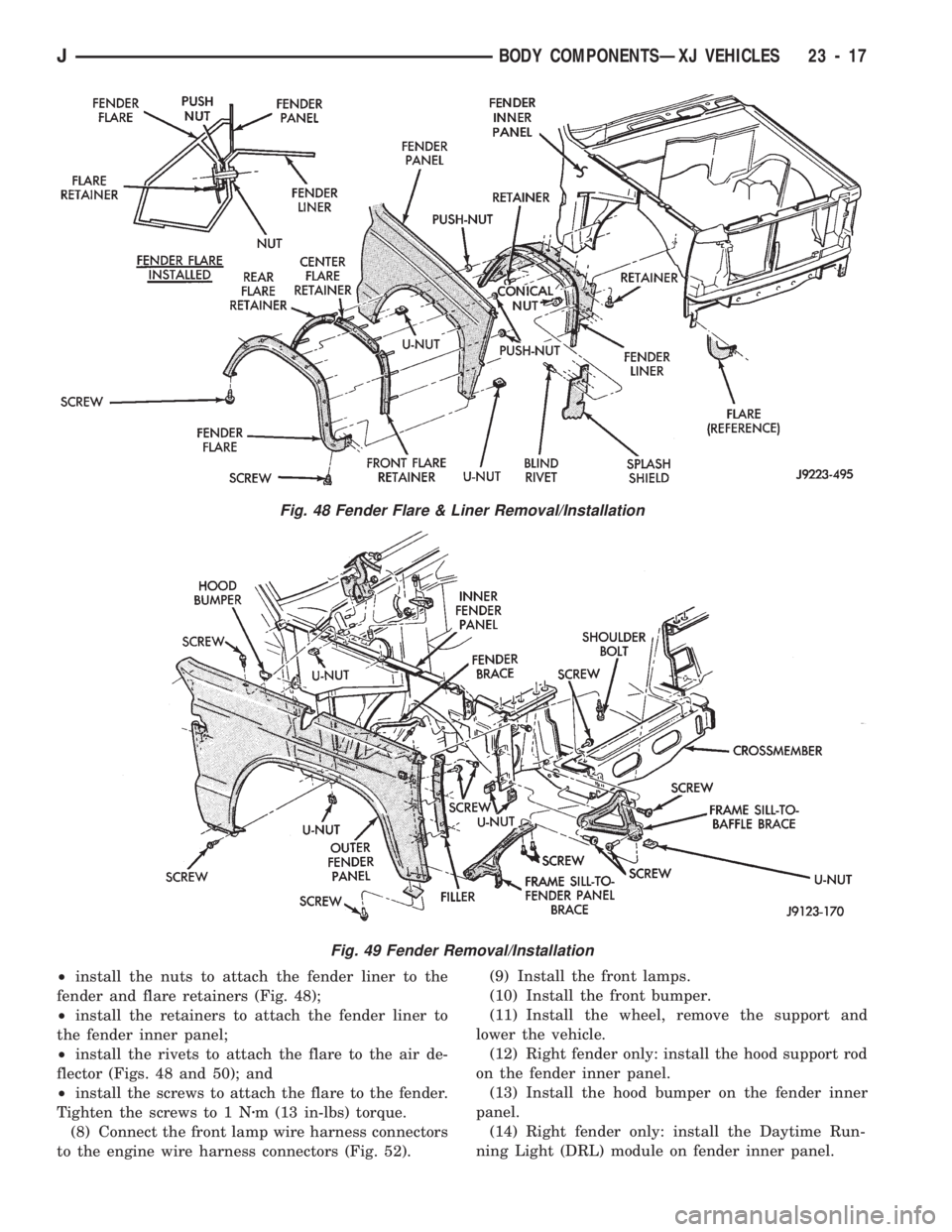
²install the nuts to attach the fender liner to the
fender and flare retainers (Fig. 48);
²install the retainers to attach the fender liner to
the fender inner panel;
²install the rivets to attach the flare to the air de-
flector (Figs. 48 and 50); and
²install the screws to attach the flare to the fender.
Tighten the screws to 1 Nzm (13 in-lbs) torque.
(8) Connect the front lamp wire harness connectors
to the engine wire harness connectors (Fig. 52).(9) Install the front lamps.
(10) Install the front bumper.
(11) Install the wheel, remove the support and
lower the vehicle.
(12) Right fender only: install the hood support rod
on the fender inner panel.
(13) Install the hood bumper on the fender inner
panel.
(14) Right fender only: install the Daytime Run-
ning Light (DRL) module on fender inner panel.
Fig. 48 Fender Flare & Liner Removal/Installation
Fig. 49 Fender Removal/Installation
JBODY COMPONENTSÐXJ VEHICLES 23 - 17
Page 1486 of 1784
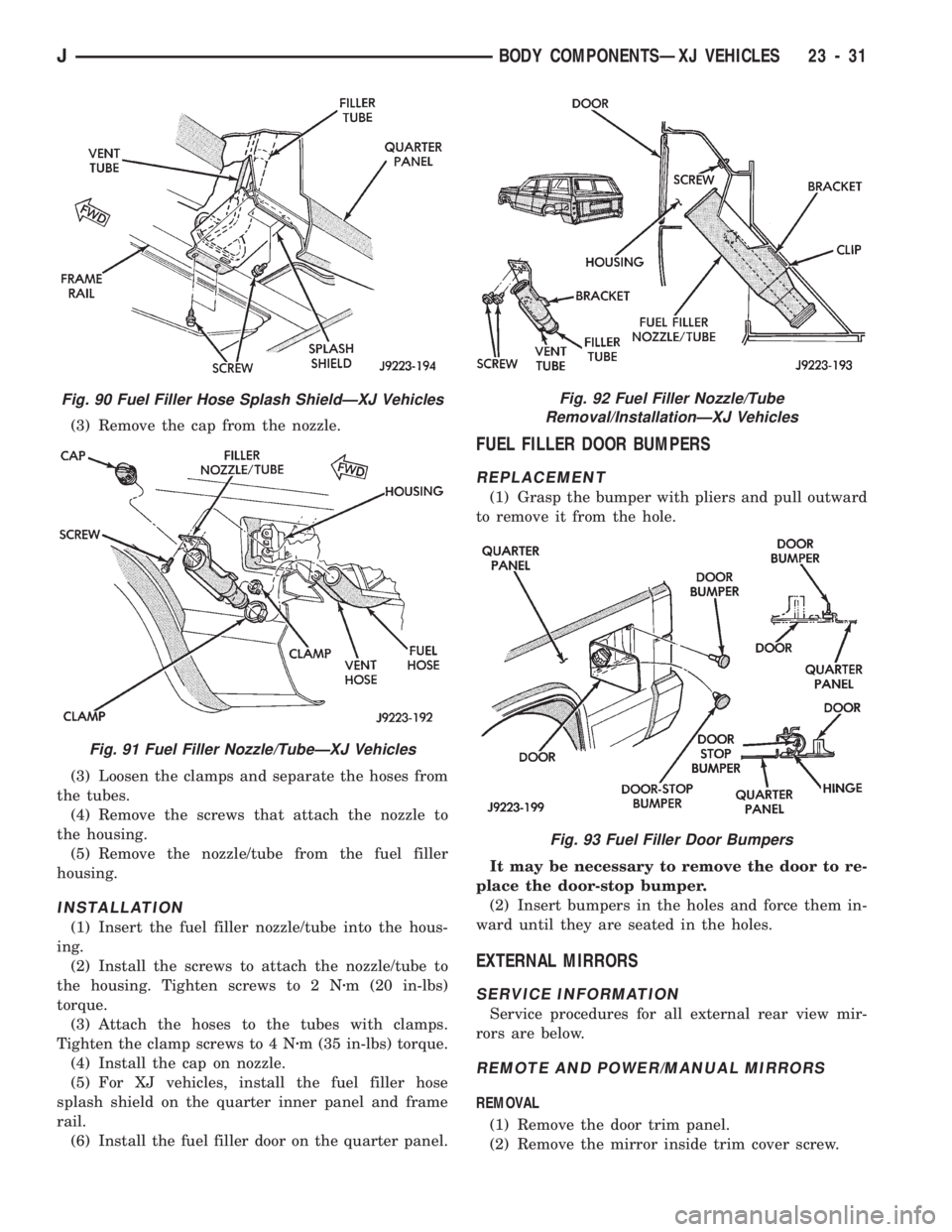
(3) Remove the cap from the nozzle.
(3) Loosen the clamps and separate the hoses from
the tubes.
(4) Remove the screws that attach the nozzle to
the housing.
(5) Remove the nozzle/tube from the fuel filler
housing.
INSTALLATION
(1) Insert the fuel filler nozzle/tube into the hous-
ing.
(2) Install the screws to attach the nozzle/tube to
the housing. Tighten screws to 2 Nzm (20 in-lbs)
torque.
(3) Attach the hoses to the tubes with clamps.
Tighten the clamp screws to 4 Nzm (35 in-lbs) torque.
(4) Install the cap on nozzle.
(5) For XJ vehicles, install the fuel filler hose
splash shield on the quarter inner panel and frame
rail.
(6) Install the fuel filler door on the quarter panel.
FUEL FILLER DOOR BUMPERS
REPLACEMENT
(1) Grasp the bumper with pliers and pull outward
to remove it from the hole.
It may be necessary to remove the door to re-
place the door-stop bumper.
(2) Insert bumpers in the holes and force them in-
ward until they are seated in the holes.
EXTERNAL MIRRORS
SERVICE INFORMATION
Service procedures for all external rear view mir-
rors are below.
REMOTE AND POWER/MANUAL MIRRORS
REMOVAL
(1) Remove the door trim panel.
(2) Remove the mirror inside trim cover screw.
Fig. 90 Fuel Filler Hose Splash ShieldÐXJ Vehicles
Fig. 91 Fuel Filler Nozzle/TubeÐXJ Vehicles
Fig. 92 Fuel Filler Nozzle/Tube
Removal/InstallationÐXJ Vehicles
Fig. 93 Fuel Filler Door Bumpers
JBODY COMPONENTSÐXJ VEHICLES 23 - 31
Page 1567 of 1784
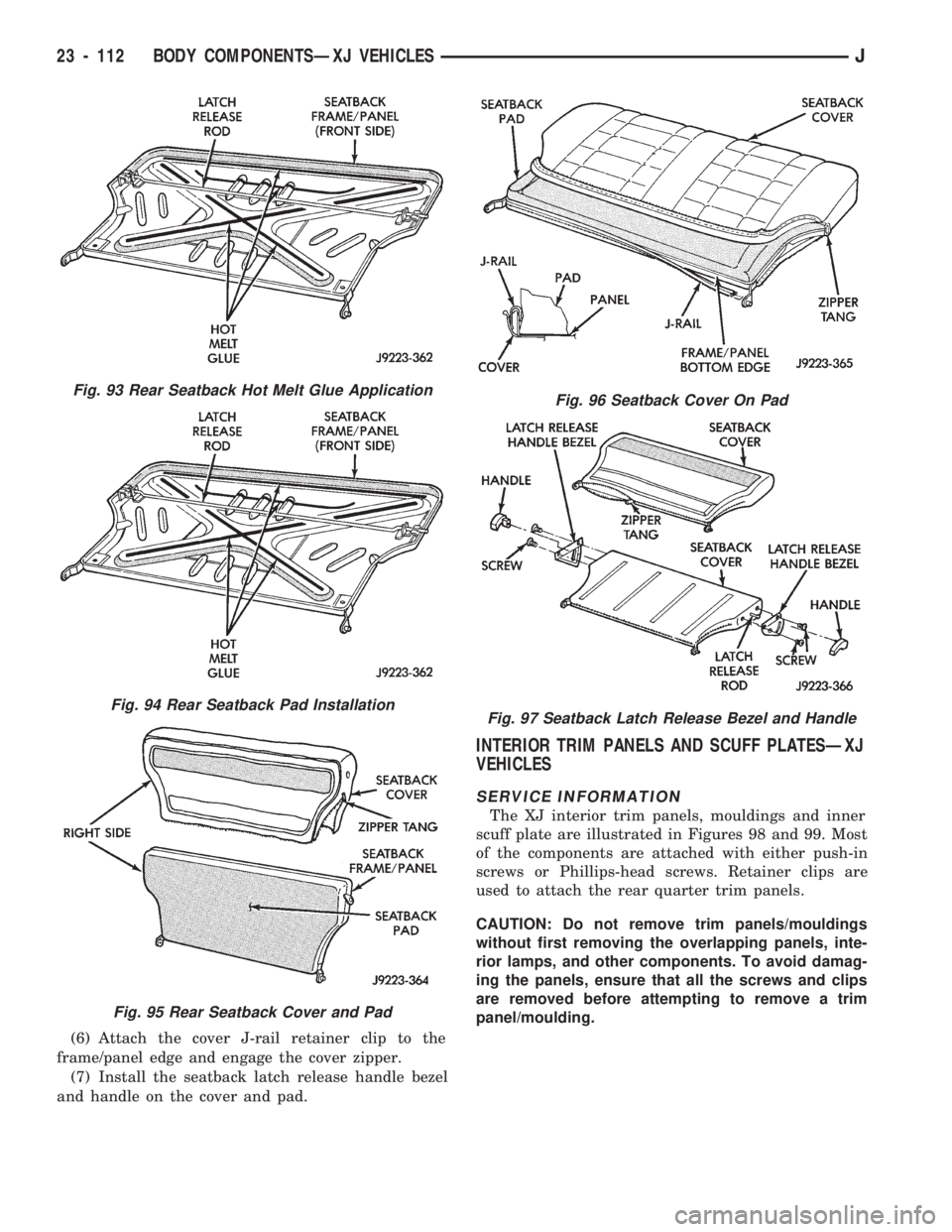
(6) Attach the cover J-rail retainer clip to the
frame/panel edge and engage the cover zipper.
(7) Install the seatback latch release handle bezel
and handle on the cover and pad.
INTERIOR TRIM PANELS AND SCUFF PLATESÐXJ
VEHICLES
SERVICE INFORMATION
The XJ interior trim panels, mouldings and inner
scuff plate are illustrated in Figures 98 and 99. Most
of the components are attached with either push-in
screws or Phillips-head screws. Retainer clips are
used to attach the rear quarter trim panels.
CAUTION: Do not remove trim panels/mouldings
without first removing the overlapping panels, inte-
rior lamps, and other components. To avoid damag-
ing the panels, ensure that all the screws and clips
are removed before attempting to remove a trim
panel/moulding.
Fig. 93 Rear Seatback Hot Melt Glue Application
Fig. 94 Rear Seatback Pad Installation
Fig. 95 Rear Seatback Cover and Pad
Fig. 96 Seatback Cover On Pad
Fig. 97 Seatback Latch Release Bezel and Handle
23 - 112 BODY COMPONENTSÐXJ VEHICLESJ
Page 1576 of 1784
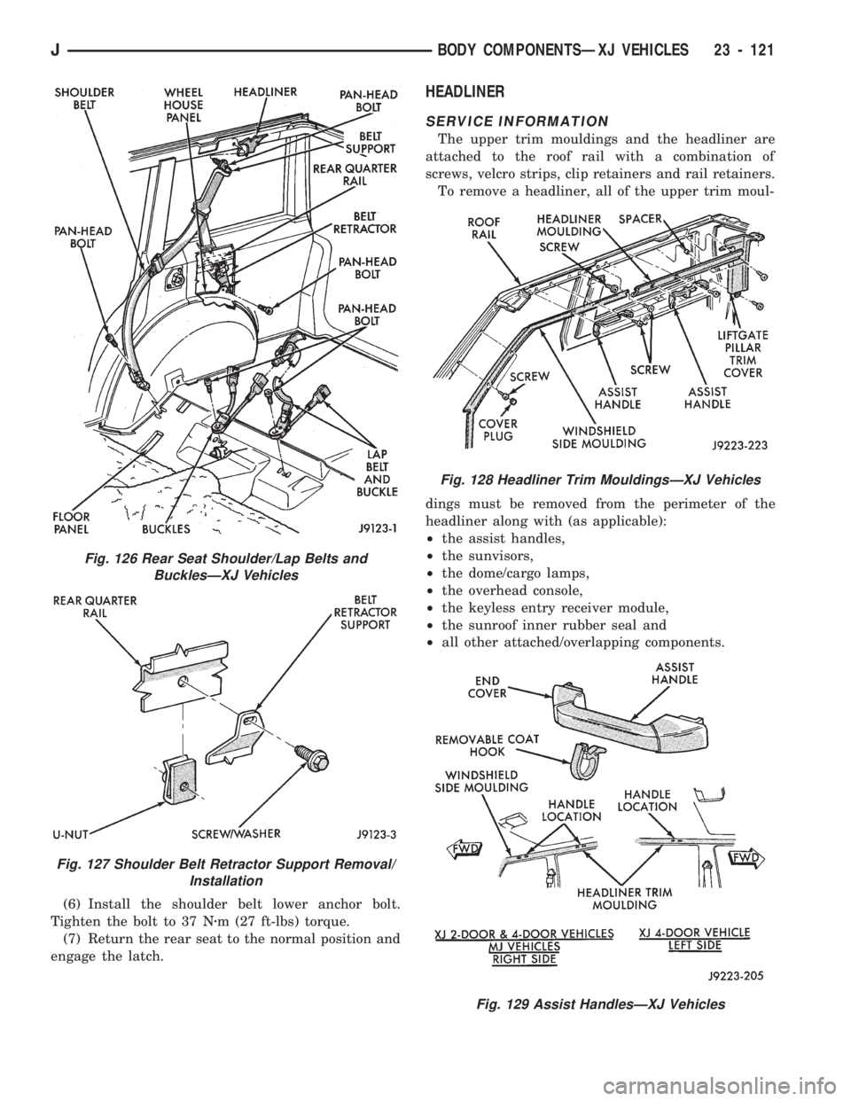
(6) Install the shoulder belt lower anchor bolt.
Tighten the bolt to 37 Nzm (27 ft-lbs) torque.
(7) Return the rear seat to the normal position and
engage the latch.
HEADLINER
SERVICE INFORMATION
The upper trim mouldings and the headliner are
attached to the roof rail with a combination of
screws, velcro strips, clip retainers and rail retainers.
To remove a headliner, all of the upper trim moul-
dings must be removed from the perimeter of the
headliner along with (as applicable):
²the assist handles,
²the sunvisors,
²the dome/cargo lamps,
²the overhead console,
²the keyless entry receiver module,
²the sunroof inner rubber seal and
²all other attached/overlapping components.
Fig. 128 Headliner Trim MouldingsÐXJ Vehicles
Fig. 129 Assist HandlesÐXJ Vehicles
Fig. 126 Rear Seat Shoulder/Lap Belts and
BucklesÐXJ Vehicles
Fig. 127 Shoulder Belt Retractor Support Removal/
Installation
JBODY COMPONENTSÐXJ VEHICLES 23 - 121
Page 1578 of 1784
HEADLINER INSTALLATION
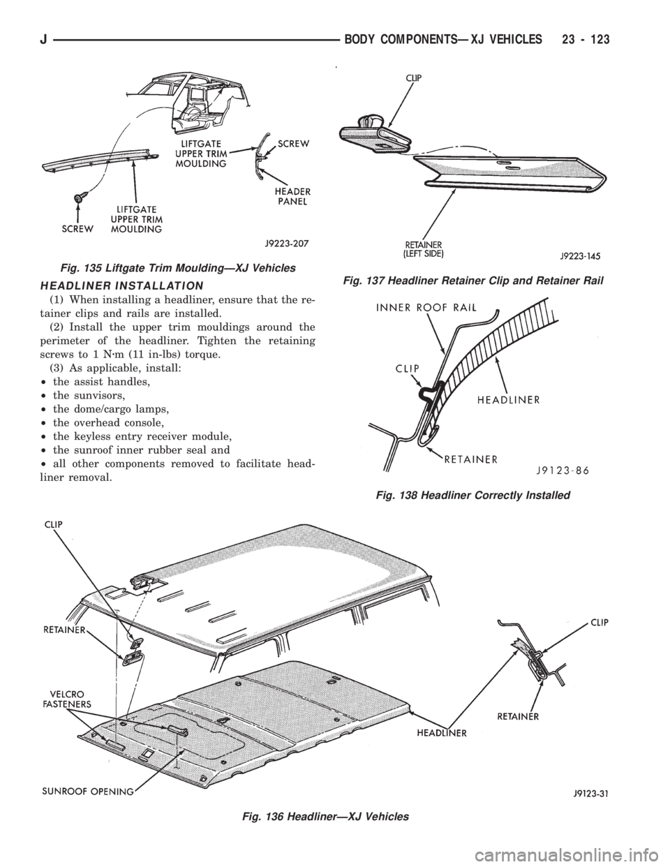
(1) When installing a headliner, ensure that the re-
tainer clips and rails are installed.
(2) Install the upper trim mouldings around the
perimeter of the headliner. Tighten the retaining
screws to 1 Nzm (11 in-lbs) torque.
(3) As applicable, install:
²the assist handles,
²the sunvisors,
²the dome/cargo lamps,
²the overhead console,
²the keyless entry receiver module,
²the sunroof inner rubber seal and
²all other components removed to facilitate head-
liner removal.
Fig. 136 HeadlinerÐXJ Vehicles
Fig. 137 Headliner Retainer Clip and Retainer Rail
Fig. 138 Headliner Correctly Installed
Fig. 135 Liftgate Trim MouldingÐXJ Vehicles
JBODY COMPONENTSÐXJ VEHICLES 23 - 123
Page 1589 of 1784
EXTERIOR COMPONENTS
INDEX
page page
Battery Tray........................... 140
Body Extension Panels and FasciasÐYJ
Renegade Vehicles..................... 147
Body Side Step Moulding................. 145
Body Stripes/Decals..................... 153
Cowl Grille and Screen................... 139
Cowl Weatherstrip Seal................... 139
Exterior Nameplates (Adhesive-Backed)....... 158
External Spare/Wheel Tire Carrier........... 172
Fender Flare........................... 144
Fender Inner Splash Shields............... 147
Fender Splash Aprons.................... 147
Fenders............................... 141
Fog LampÐYJ Renegade Vehicles.......... 150
Front Fascia and Skid PlateÐYJ Renegade
Vehicles............................. 148
Front Fender Extension PanelÐYJ Renegade
Vehicles............................. 149
Fuel Filler Protector/Nozzle................ 158
Half Metal Door Mirror (External)............ 158
Hard Top Liftgate Glass.................. 162
Hard Top Repair........................ 165
Hard Top Roof Vent..................... 165
Hard Top Service....................... 164
Hard Top Service Information.............. 164Hood................................. 137
Hood Alignment......................... 138
Hood Insulator Panel..................... 138
Hood Safety Latch....................... 139
Liftgate Glass Weatherstrip Seal Replacement . . 163
Radiator Grille Applique................... 134
Rear Fascia and Skid PlateÐYJ Renegade
Vehicles............................. 152
Rear Quarter Extension PanelÐYJ Renegade
Vehicles............................. 151
Rocker Extension PanelÐYJ Renegade
Vehicles............................. 150
Soft Top Service........................ 167
Soft Top Service Information............... 166
Sport Bar............................. 171
Tailgate Adjustment...................... 160
Tailgate Hinge.......................... 159
Tailgate Latch and Release Handle.......... 160
Tailgate Latch Striker..................... 161
Tailgate Lock Cylinder.................... 160
Tailgate Service......................... 159
Tailgate Service Information................ 159
Tailgate Weatherstrip Seal................. 161
Wheelhouse Splash Liners................ 146
RADIATOR GRILLE APPLIQUE
REMOVAL
(1) Raise the hood.
(2) Remove the headlamp bezels (Fig. 1).
(3) Remove the headlamp bulb retainer screws
(Fig. 2).
(4) Disconnect and remove the headlamps and
buckets as a unit (Fig. 2).
(5) Remove the parking lamp retaining screws
(Fig. 2).
(6) Disconnect the wire harness connectors and re-
move the parking lamps (Fig. 2).
(7) Remove the front crossmember cover.
(8) Remove the retaining screws and the bumper
inserts at the top of the grille panel (Fig. 1).
(9) Detach the grille applique from the grille panel
(Fig. 1).
(10) Remove the double faced foam adhesive tape
at the bottom of the grille applique (Fig. 1).
INSTALLATION
(1) Install double faced foam tape at the bottom,
interior side of the grille applique (Fig. 1).
(2) Position the grille applique over the grille
panel and press inward along the bottom where the
tape is located (Fig. 1).
(3) Install the grille applique retaining screws and
the bumper inserts (Fig. 1).(4) Connect the wire harness connectors and posi-
tion the headlamp buckets and headlamps in the
grille panel (Fig. 2).
(5) Install the headlamp bulb retainer and the
screws (Fig. 1). Tighten the screws to 2 Nzm (18 in-
lbs) torque.
(6) Install the headlamp bezels and the retaining
screws (Fig. 1). Tighten the screws securely.
(7) Connect the wire harness connectors and in-
stall the parking lamps (Fig. 2).
(8) Install the parking lamp retaining screws.
Tighten the screws to 2 Nzm (18 in-lbs) torque.
(9) Close the hood.
(10) Install the front crossmember cover.
23 - 134 BODY COMPONENTSÐXJ VEHICLESJ