1994 JEEP CHEROKEE lamps
[x] Cancel search: lampsPage 974 of 1784
REMOVALÐXJ MODELS
Perform the preceding Fuel System Pressure Re-
lease Procedure.
(1) Disconnect negative battery cable.
(2) Remove the fuel filler cap. Using an approved
portable gasoline siphon/storage tank, drain fuel
tank.
(3) Raise and support vehicle.
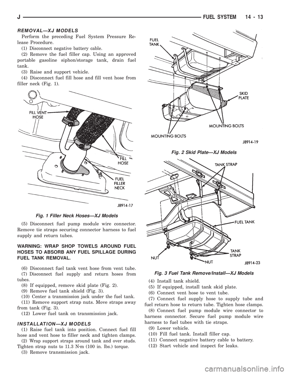
(4) Disconnect fuel fill hose and fill vent hose from
filler neck (Fig. 1).
(5) Disconnect fuel pump module wire connector.
Remove tie straps securing connector harness to fuel
supply and return tubes.
WARNING: WRAP SHOP TOWELS AROUND FUEL
HOSES TO ABSORB ANY FUEL SPILLAGE DURING
FUEL TANK REMOVAL.
(6) Disconnect fuel tank vent hose from vent tube.
(7) Disconnect fuel supply and return hoses from
tubes.
(8) If equipped, remove skid plate (Fig. 2).
(9) Remove fuel tank shield (Fig. 3).
(10) Center a transmission jack under the fuel tank.
(11) Remove support strap nuts. Move straps away
from tank (Fig. 3).
(12) Lower fuel tank on transmission jack.
INSTALLATIONÐXJ MODELS
(1) Raise fuel tank into position. Connect fuel fill
hose and vent hose to filler neck and tighten clamps.
(2) Wrap support straps around tank and over studs.
Tighten strap nuts to 11.3 Nzm (100 in. lbs.) torque.
(3) Remove transmission jack.(4) Install tank shield.
(5) If equipped, install tank skid plate.
(6) Connect vent hose to vent tube.
(7) Connect fuel supply hose to supply tube and
fuel return hose to return tube. Tighten hose clamps.
(8) Connect fuel pump module wire connector to
harness connector. Secure fuel pump module wire
harness to fuel tubes with tie straps.
(9) Lower vehicle.
(10) Fill fuel tank. Install filler cap.
(11) Connect negative battery cable to battery.
(12) Start vehicle and inspect for leaks.
Fig. 1 Filler Neck HosesÐXJ Models
Fig. 2 Skid PlateÐXJ Models
Fig. 3 Fuel Tank Remove/InstallÐXJ Models
JFUEL SYSTEM 14 - 13
Page 976 of 1784
INSTALLATIONÐYJ MODELS
(1) Place tank into skid plate. Wrap straps around
tank with strap bolts inserted through holes in skid
plate. Tighten strap nuts to 7.3 Nzm (65 in. lbs.) torque.
(2) Raise skid plate/fuel tank until gauge sender wire
connector can be connected to harness connector.
(3) Finish raising skid plate/fuel tank assembly
into position. Tighten mounting nuts to 16 Nzm (12
ft. lbs.) torque. Remove transmission jack.
(4) Connect fuel fill hose and fill vent hose to filler
neck. Tighten hose clamps.
(5) Connect vent hose to vent tube.
(6) Connect fuel supply hose to the supply tube and
fuel return hose to return tube. Tighten hose clamps.
(7) Install fuel filler neck shroud with push clips.
(8) Lower vehicle.
(9) Fill fuel tank. Install filler cap.
(10) Connect negative battery cable to battery.
(11) Start vehicle and inspect for leaks.
FUEL GAUGE SENDING UNIT
The fuel gauge sending unit is attached to the fuel
pump module. Refer to Fuel Pump Module in the
Fuel Delivery System section of this group.
FUEL TANK PRESSURE RELIEF/ROLLOVER VALVE
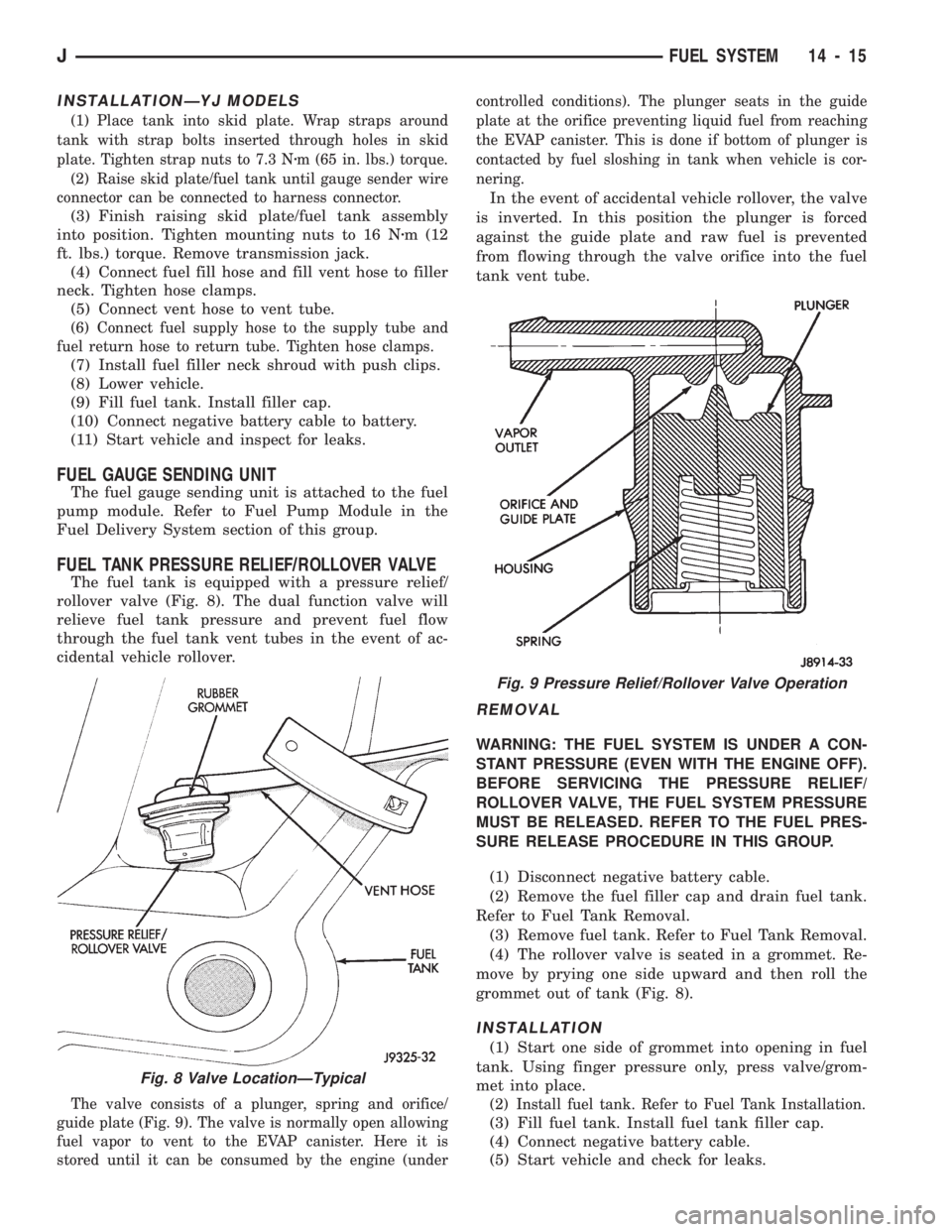
The fuel tank is equipped with a pressure relief/
rollover valve (Fig. 8). The dual function valve will
relieve fuel tank pressure and prevent fuel flow
through the fuel tank vent tubes in the event of ac-
cidental vehicle rollover.
The valve consists of a plunger, spring and orifice/
guide plate (Fig. 9). The valve is normally open allowing
fuel vapor to vent to the EVAP canister. Here it is
stored until it can be consumed by the engine (undercontrolled conditions). The plunger seats in the guide
plate at the orifice preventing liquid fuel from reaching
the EVAP canister. This is done if bottom of plunger is
contacted by fuel sloshing in tank when vehicle is cor-
nering.
In the event of accidental vehicle rollover, the valve
is inverted. In this position the plunger is forced
against the guide plate and raw fuel is prevented
from flowing through the valve orifice into the fuel
tank vent tube.
REMOVAL
WARNING: THE FUEL SYSTEM IS UNDER A CON-
STANT PRESSURE (EVEN WITH THE ENGINE OFF).
BEFORE SERVICING THE PRESSURE RELIEF/
ROLLOVER VALVE, THE FUEL SYSTEM PRESSURE
MUST BE RELEASED. REFER TO THE FUEL PRES-
SURE RELEASE PROCEDURE IN THIS GROUP.
(1) Disconnect negative battery cable.
(2) Remove the fuel filler cap and drain fuel tank.
Refer to Fuel Tank Removal.
(3) Remove fuel tank. Refer to Fuel Tank Removal.
(4) The rollover valve is seated in a grommet. Re-
move by prying one side upward and then roll the
grommet out of tank (Fig. 8).
INSTALLATION
(1) Start one side of grommet into opening in fuel
tank. Using finger pressure only, press valve/grom-
met into place.
(2) Install fuel tank. Refer to Fuel Tank Installation.
(3) Fill fuel tank. Install fuel tank filler cap.
(4) Connect negative battery cable.
(5) Start vehicle and check for leaks.
Fig. 8 Valve LocationÐTypical
Fig. 9 Pressure Relief/Rollover Valve Operation
JFUEL SYSTEM 14 - 15
Page 1015 of 1784
MULTI-PORT FUEL INJECTION (MFI)ÐCOMPONENT REMOVAL/INSTALLATION
INDEX
page page
Accelerator Pedal and Throttle Cable......... 54
Air Cleaner Housing...................... 54
Air Conditioning (A/C) Clutch Relay........... 54
Air Filter............................... 54
Automatic Shut Down (ASD) Relay........... 54
Brake Switch............................ 54
Camshaft Position Sensor.................. 54
Crankshaft Position Sensor................. 55
Engine Coolant Temperature Sensor.......... 55
Fuel Filter.............................. 55
Fuel Injector............................ 55
Fuel Pump Module....................... 56
Fuel Pump Relay........................ 56
Fuel Rail Assembly....................... 56
Fuel System Pressure Release Procedure...... 56
Fuel Tank Pressure Relief/Rollover Valve...... 56
Fuel Tanks............................. 56Fuel Tubes/Lines/Hoses and Clamps.......... 56
Idle Air Control (IAC) Motor................. 56
Ignition Coil............................. 57
Intake Air Temperature Sensor.............. 54
Intake Manifold.......................... 57
Manifold Absolute Pressure (MAP) Sensor..... 57
Oxygen (O2S) Sensor..................... 57
Park Neutral Switch....................... 58
Power Steering Pressure SwitchÐ2.5L
Engine Only........................... 58
Powertrain Control Module (PCM)............ 58
Quick-Connect Fittings..................... 59
Throttle Body............................ 59
Throttle Position Sensor (TPS).............. 59
Torque Converter Clutch Relay.............. 60
Vehicle Speed Sensor..................... 60
ACCELERATOR PEDAL AND THROTTLE CABLE
Refer to the Accelerator Pedal and Throttle Cable
section of this group for removal/installation proce-
dures.
AIR CONDITIONING (A/C) CLUTCH RELAY
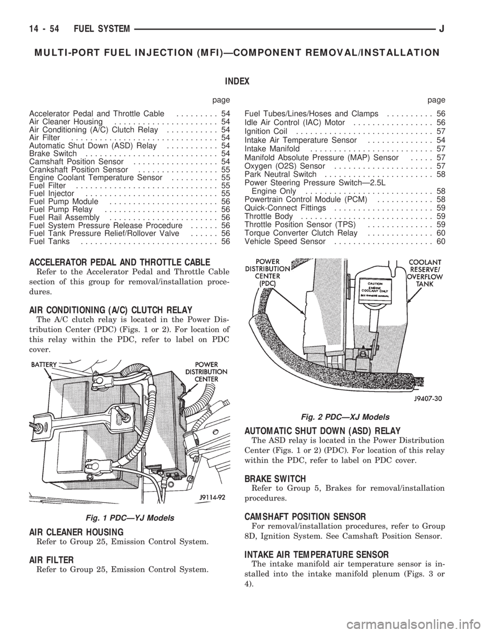
The A/C clutch relay is located in the Power Dis-
tribution Center (PDC) (Figs. 1 or 2). For location of
this relay within the PDC, refer to label on PDC
cover.
AIR CLEANER HOUSING
Refer to Group 25, Emission Control System.
AIR FILTER
Refer to Group 25, Emission Control System.
AUTOMATIC SHUT DOWN (ASD) RELAY
The ASD relay is located in the Power Distribution
Center (Figs. 1 or 2) (PDC). For location of this relay
within the PDC, refer to label on PDC cover.
BRAKE SWITCH
Refer to Group 5, Brakes for removal/installation
procedures.
CAMSHAFT POSITION SENSOR
For removal/installation procedures, refer to Group
8D, Ignition System. See Camshaft Position Sensor.
INTAKE AIR TEMPERATURE SENSOR
The intake manifold air temperature sensor is in-
stalled into the intake manifold plenum (Figs. 3 or
4).
Fig. 1 PDCÐYJ Models
Fig. 2 PDCÐXJ Models
14 - 54 FUEL SYSTEMJ
Page 1017 of 1784
INSTALLATION
(1) Install the fuel injector(s) into the fuel rail as-
sembly and install retaining clip(s).
(2) Install fuel rail. Refer to Fuel Rail Installation
in this section.
(3) Start engine and check for fuel leaks.
FUEL PUMP MODULE
Refer to the Fuel Delivery System section of this
group for removal/installation procedures.
FUEL PUMP RELAY
The Fuel Pump relay is located in the Power Dis-
tribution Center (PDC) (Figs. 1 or 2). For location of
this relay within the PDC, refer to label on PDC
cover.
FUEL RAIL ASSEMBLY
REMOVAL
WARNING: THE FUEL SYSTEM IS UNDER CON-
STANT FUEL PRESSURE (EVEN WITH THE ENGINE
OFF) OF APPROXIMATELY 131-269 KPA (19-39
PSI). THIS PRESSURE MUST BE RELEASED BE-
FORE SERVICING THE FUEL RAIL.
(1) Remove fuel tank filler tube cap.
(2) Disconnect the negative battery cable from bat-
tery.
(3) Perform the Fuel System Pressure Release Pro-
cedure as described in the Fuel Delivery System sec-
tion of this Group.
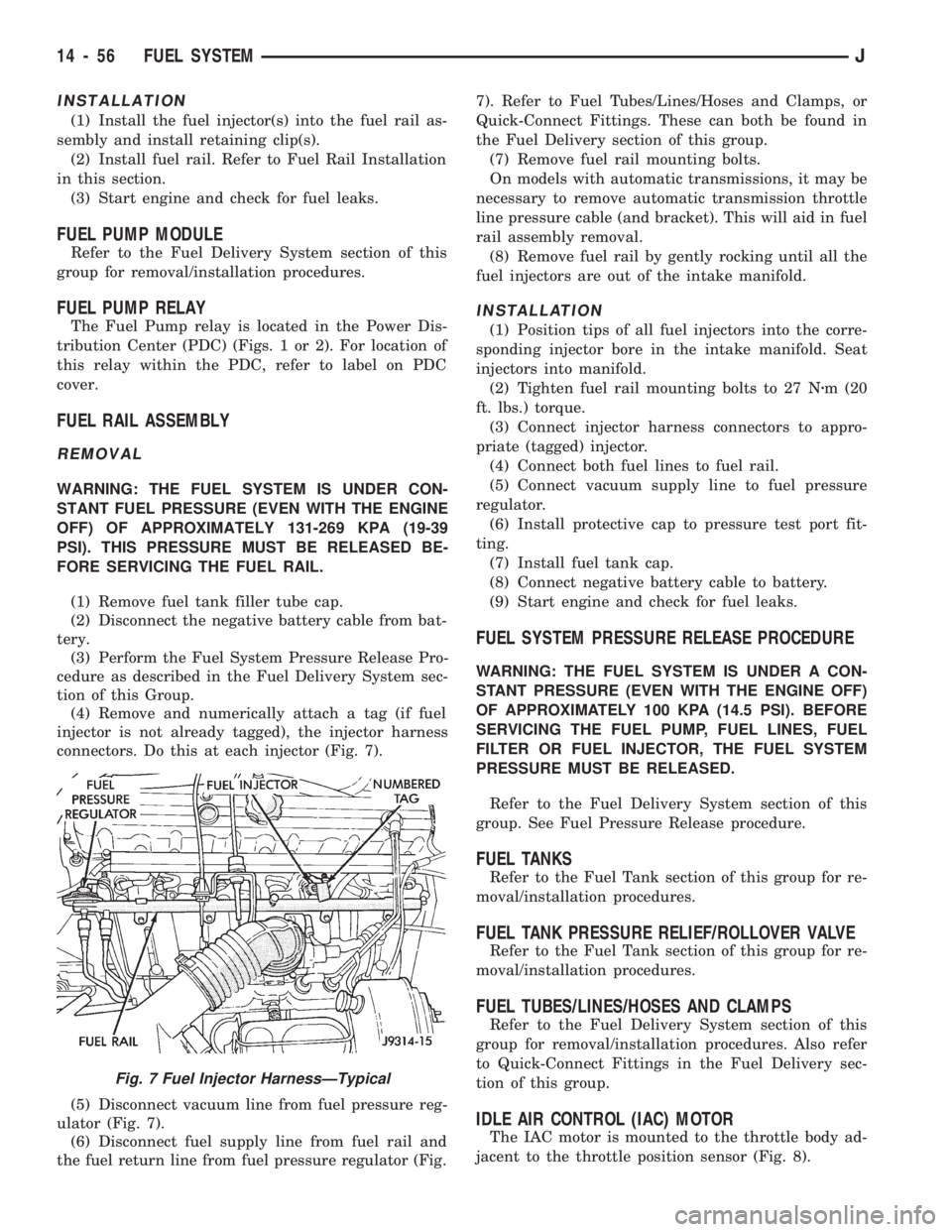
(4) Remove and numerically attach a tag (if fuel
injector is not already tagged), the injector harness
connectors. Do this at each injector (Fig. 7).
(5) Disconnect vacuum line from fuel pressure reg-
ulator (Fig. 7).
(6) Disconnect fuel supply line from fuel rail and
the fuel return line from fuel pressure regulator (Fig.7). Refer to Fuel Tubes/Lines/Hoses and Clamps, or
Quick-Connect Fittings. These can both be found in
the Fuel Delivery section of this group.
(7) Remove fuel rail mounting bolts.
On models with automatic transmissions, it may be
necessary to remove automatic transmission throttle
line pressure cable (and bracket). This will aid in fuel
rail assembly removal.
(8) Remove fuel rail by gently rocking until all the
fuel injectors are out of the intake manifold.
INSTALLATION
(1) Position tips of all fuel injectors into the corre-
sponding injector bore in the intake manifold. Seat
injectors into manifold.
(2) Tighten fuel rail mounting bolts to 27 Nzm (20
ft. lbs.) torque.
(3) Connect injector harness connectors to appro-
priate (tagged) injector.
(4) Connect both fuel lines to fuel rail.
(5) Connect vacuum supply line to fuel pressure
regulator.
(6) Install protective cap to pressure test port fit-
ting.
(7) Install fuel tank cap.
(8) Connect negative battery cable to battery.
(9) Start engine and check for fuel leaks.
FUEL SYSTEM PRESSURE RELEASE PROCEDURE
WARNING: THE FUEL SYSTEM IS UNDER A CON-
STANT PRESSURE (EVEN WITH THE ENGINE OFF)
OF APPROXIMATELY 100 KPA (14.5 PSI). BEFORE
SERVICING THE FUEL PUMP, FUEL LINES, FUEL
FILTER OR FUEL INJECTOR, THE FUEL SYSTEM
PRESSURE MUST BE RELEASED.
Refer to the Fuel Delivery System section of this
group. See Fuel Pressure Release procedure.
FUEL TANKS
Refer to the Fuel Tank section of this group for re-
moval/installation procedures.
FUEL TANK PRESSURE RELIEF/ROLLOVER VALVE
Refer to the Fuel Tank section of this group for re-
moval/installation procedures.
FUEL TUBES/LINES/HOSES AND CLAMPS
Refer to the Fuel Delivery System section of this
group for removal/installation procedures. Also refer
to Quick-Connect Fittings in the Fuel Delivery sec-
tion of this group.
IDLE AIR CONTROL (IAC) MOTOR
The IAC motor is mounted to the throttle body ad-
jacent to the throttle position sensor (Fig. 8).
Fig. 7 Fuel Injector HarnessÐTypical
14 - 56 FUEL SYSTEMJ
Page 1027 of 1784
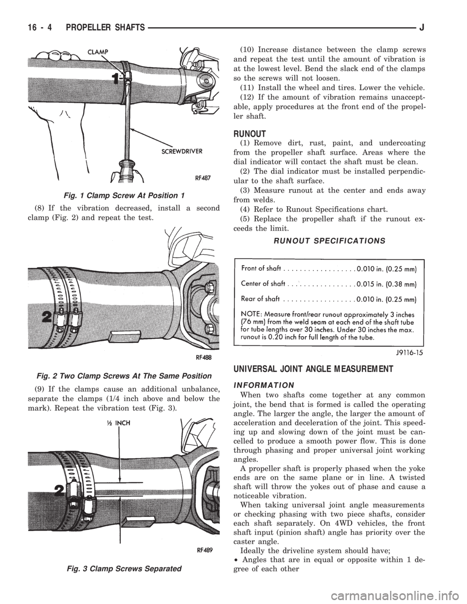
(8) If the vibration decreased, install a second
clamp (Fig. 2) and repeat the test.
(9) If the clamps cause an additional unbalance,
separate the clamps (1/4 inch above and below the
mark). Repeat the vibration test (Fig. 3).(10) Increase distance between the clamp screws
and repeat the test until the amount of vibration is
at the lowest level. Bend the slack end of the clamps
so the screws will not loosen.
(11) Install the wheel and tires. Lower the vehicle.
(12) If the amount of vibration remains unaccept-
able, apply procedures at the front end of the propel-
ler shaft.
RUNOUT
(1) Remove dirt, rust, paint, and undercoating
from the propeller shaft surface. Areas where the
dial indicator will contact the shaft must be clean.
(2) The dial indicator must be installed perpendic-
ular to the shaft surface.
(3) Measure runout at the center and ends away
from welds.
(4) Refer to Runout Specifications chart.
(5) Replace the propeller shaft if the runout ex-
ceeds the limit.
UNIVERSAL JOINT ANGLE MEASUREMENT
INFORMATION
When two shafts come together at any common
joint, the bend that is formed is called the operating
angle. The larger the angle, the larger the amount of
acceleration and deceleration of the joint. This speed-
ing up and slowing down of the joint must be can-
celled to produce a smooth power flow. This is done
through phasing and proper universal joint working
angles.
A propeller shaft is properly phased when the yoke
ends are on the same plane or in line. A twisted
shaft will throw the yokes out of phase and cause a
noticeable vibration.
When taking universal joint angle measurements
or checking phasing with two piece shafts, consider
each shaft separately. On 4WD vehicles, the front
shaft input (pinion shaft) angle has priority over the
caster angle.
Ideally the driveline system should have;
²Angles that are in equal or opposite within 1 de-
gree of each other
Fig. 1 Clamp Screw At Position 1
Fig. 2 Two Clamp Screws At The Same Position
Fig. 3 Clamp Screws Separated
RUNOUT SPECIFICATIONS
16 - 4 PROPELLER SHAFTSJ
Page 1046 of 1784
POWER STEERING PUMP
INDEX
page page
Drive Pulley Replacement.................. 11
Flow Control Valve Fitting O-Ring Seal........ 12
Power Steering PumpÐInitial Operation....... 13
Pressure and Return Hose Replacement........ 9Pump Replacement....................... 10
Reservoir Replacement.................... 12
Service Information........................ 9
SERVICE INFORMATION
The power steering pump internal components are
not serviced or adjusted. If a malfunction or an inter-
nal fluid leak occurs, the complete unit must be re-
placed. A reservoir, cap, and O-ring seal kit are the
only service components available.
PRESSURE AND RETURN HOSE REPLACEMENT
Cap hose open ends and pump/steering gear fit-
tings to prevent entry of foreign material.
WARNING: POWER STEERING FLUID (AND PUMP
COMPONENTS) AND THE EXHAUST SYSTEM CAN
BE EXTREMELY HOT IF THE ENGINE HAS BEEN
RECENTLY OPERATING. DO NOT START THE EN-
GINE WITH ANY LOOSE OR DISCONNECTED
HOSES. DO NOT ALLOW THE HOSES TO TOUCH A
HOT EXHAUST MANIFOLD OR THE CATALYTIC
CONVERTER.
REMOVAL
(1) Remove fasteners from hose retaining brackets
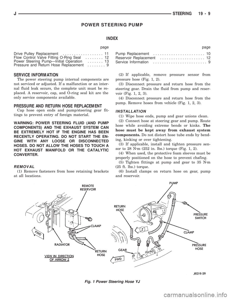
at all locations.(2) If applicable, remove pressure sensor from
pressure hose (Fig. 1, 2).
(3) Disconnect pressure and return hose from the
steering gear. Drain the fluid from pump and reser-
voir (Fig. 1, 2, 3).
(4) Disconnect pressure and return hose from the
pump. Remove hoses from vehicle (Fig. 1, 2, 3).
INSTALLATION
(1) Wipe hose ends, pump and gear unions clean.
(2) Connect hose at steering gear and pump. Route
hose while avoiding extreme bends or kinks.The
hose must be kept away from exhaust system
components.Do not distort hose tube ends by bend-
ing, kinking or over tightening.
(3) If applicable, install and tighten pressure sen-
sor to 28 Nzm (252 in. lbs.) torque (Fig. 1, 2).
(4) When used, the protective foam sleeves must be
properly positioned on the hose to prevent chafing.
(5) Tighten fittings at pump and gear to 35 Nzm
(25 ft. lbs.) torque.
(6) Install clamps on return hose on gear, pump
and reservoir.
Fig. 1 Power Steering Hose YJ
JSTEERING 19 - 9
Page 1303 of 1784
AW-4 TRANSMISSION OVERHAUL
INDEX
page page
Cleaning and Inspection................... 76
Direct Clutch Overhaul................... 219
First-Reverse Brake Piston and Transmission
Case Overhaul........................ 237
Forward Clutch Overhaul.................. 223
Front Planetary Gear Overhaul............. 228
Manual Valve Shaft Overhaul.............. 205
Oil Pump Overhaul...................... 206
Overdrive Planetary Gear and Clutch Overhaul . 209Overdrive Support Overhaul................ 216
Overhaul Service Tools................... 192
Rear Planetary, No. 2 One-Way Clutch and
Output Shaft Overhaul.................. 100
Second Brake Overhaul................... 100
Sun Gear and No. 1 One-Way Clutch Overhaul . 99
Transmission Assembly and Adjustment....... 255
Transmission Disassembly................. 192
Transmission Valve Body Overhaul.......... 101
OVERHAUL SERVICE TOOLS
The special tools needed to overhaul the AW-4
transmission are provided in Tool Kit 6294. However,
Pressure Test Port Adapter 7554 is not included in
this kit and must be ordered separately. The over-
haul tool kit and test port adapter are available
through the parts division and dealer special tool
program.
TRANSMISSION DISASSEMBLY
(1) Remove torque converter.
(2) Remove lower half of filler tube if not previ-
ously removed.
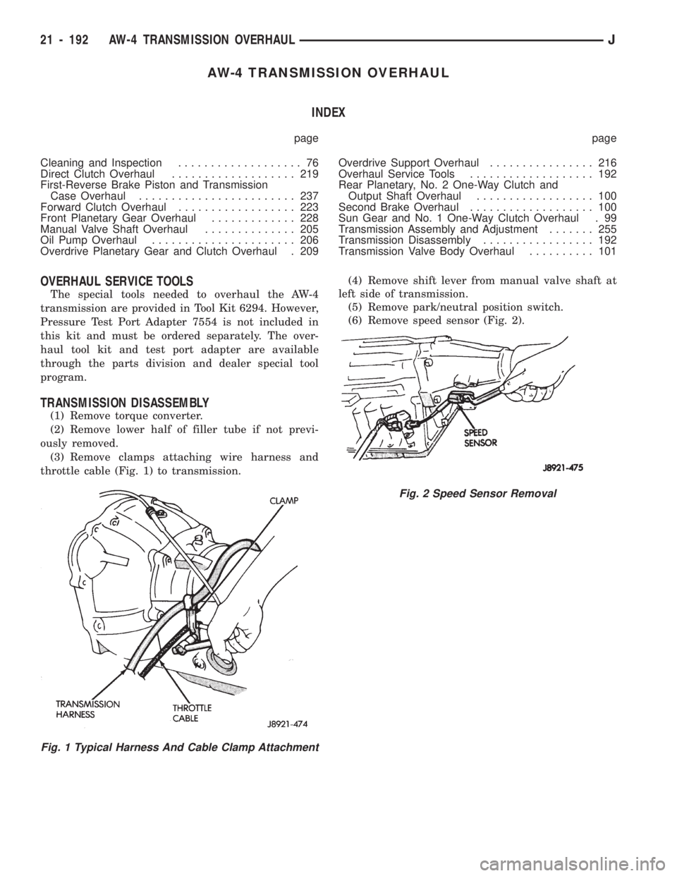
(3) Remove clamps attaching wire harness and
throttle cable (Fig. 1) to transmission.(4) Remove shift lever from manual valve shaft at
left side of transmission.
(5) Remove park/neutral position switch.
(6) Remove speed sensor (Fig. 2).
Fig. 1 Typical Harness And Cable Clamp Attachment
Fig. 2 Speed Sensor Removal
21 - 192 AW-4 TRANSMISSION OVERHAULJ
Page 1382 of 1784
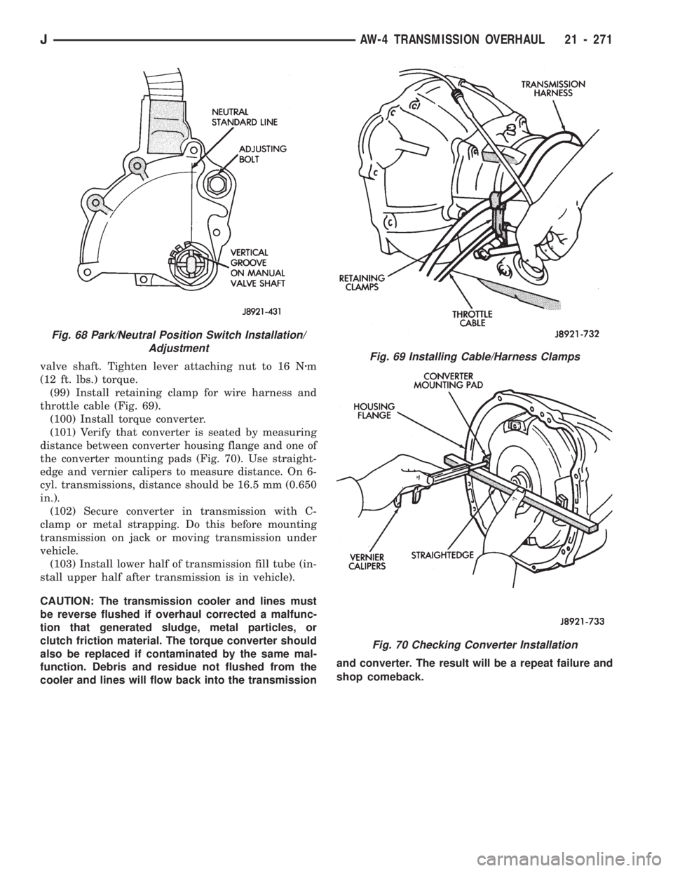
valve shaft. Tighten lever attaching nut to 16 Nzm
(12 ft. lbs.) torque.
(99) Install retaining clamp for wire harness and
throttle cable (Fig. 69).
(100) Install torque converter.
(101) Verify that converter is seated by measuring
distance between converter housing flange and one of
the converter mounting pads (Fig. 70). Use straight-
edge and vernier calipers to measure distance. On 6-
cyl. transmissions, distance should be 16.5 mm (0.650
in.).
(102) Secure converter in transmission with C-
clamp or metal strapping. Do this before mounting
transmission on jack or moving transmission under
vehicle.
(103) Install lower half of transmission fill tube (in-
stall upper half after transmission is in vehicle).
CAUTION: The transmission cooler and lines must
be reverse flushed if overhaul corrected a malfunc-
tion that generated sludge, metal particles, or
clutch friction material. The torque converter should
also be replaced if contaminated by the same mal-
function. Debris and residue not flushed from the
cooler and lines will flow back into the transmissionand converter. The result will be a repeat failure and
shop comeback.Fig. 69 Installing Cable/Harness Clamps
Fig. 70 Checking Converter Installation
Fig. 68 Park/Neutral Position Switch Installation/
Adjustment
JAW-4 TRANSMISSION OVERHAUL 21 - 271