1994 JEEP CHEROKEE battery
[x] Cancel search: batteryPage 337 of 1784
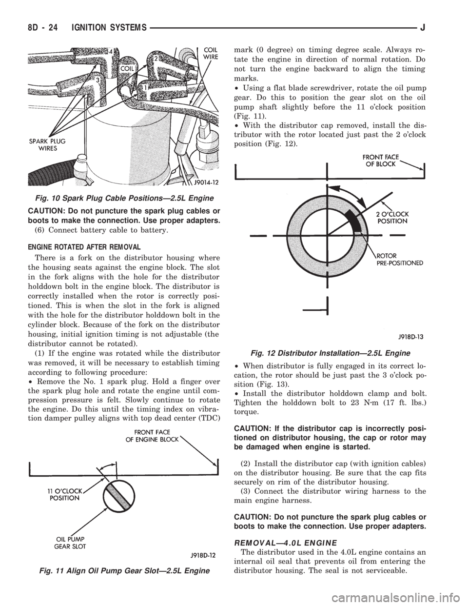
CAUTION: Do not puncture the spark plug cables or
boots to make the connection. Use proper adapters.
(6) Connect battery cable to battery.
ENGINE ROTATED AFTER REMOVAL
There is a fork on the distributor housing where
the housing seats against the engine block. The slot
in the fork aligns with the hole for the distributor
holddown bolt in the engine block. The distributor is
correctly installed when the rotor is correctly posi-
tioned. This is when the slot in the fork is aligned
with the hole for the distributor holddown bolt in the
cylinder block. Because of the fork on the distributor
housing, initial ignition timing is not adjustable (the
distributor cannot be rotated).
(1) If the engine was rotated while the distributor
was removed, it will be necessary to establish timing
according to following procedure:
²Remove the No. 1 spark plug. Hold a finger over
the spark plug hole and rotate the engine until com-
pression pressure is felt. Slowly continue to rotate
the engine. Do this until the timing index on vibra-
tion damper pulley aligns with top dead center (TDC)mark (0 degree) on timing degree scale. Always ro-
tate the engine in direction of normal rotation. Do
not turn the engine backward to align the timing
marks.
²Using a flat blade screwdriver, rotate the oil pump
gear. Do this to position the gear slot on the oil
pump shaft slightly before the 11 o'clock position
(Fig. 11).
²With the distributor cap removed, install the dis-
tributor with the rotor located just past the 2 o'clock
position (Fig. 12).
²When distributor is fully engaged in its correct lo-
cation, the rotor should be just past the 3 o'clock po-
sition (Fig. 13).
²Install the distributor holddown clamp and bolt.
Tighten the holddown bolt to 23 Nzm (17 ft. lbs.)
torque.
CAUTION: If the distributor cap is incorrectly posi-
tioned on distributor housing, the cap or rotor may
be damaged when engine is started.
(2) Install the distributor cap (with ignition cables)
on the distributor housing. Be sure that the cap fits
securely on rim of the distributor housing.
(3) Connect the distributor wiring harness to the
main engine harness.
CAUTION: Do not puncture the spark plug cables or
boots to make the connection. Use proper adapters.
REMOVALÐ4.0L ENGINE
The distributor used in the 4.0L engine contains an
internal oil seal that prevents oil from entering the
distributor housing. The seal is not serviceable.
Fig. 11 Align Oil Pump Gear SlotÐ2.5L Engine
Fig. 10 Spark Plug Cable PositionsÐ2.5L Engine
Fig. 12 Distributor InstallationÐ2.5L Engine
8D - 24 IGNITION SYSTEMSJ
Page 338 of 1784
The camshaft position sensor is located in the dis-
tributor on all engines (Fig. 9).
Refer to figure 9 for an exploded view of the dis-
tributor.
(1) Disconnect the negative battery cable at bat-
tery.
(2) On XJ models equipped with A/C, remove the
electrical cooling fan and shroud assembly from the
radiator. This will provide room to turn the engine
with a socket and ratchet using the vibration damper
bolt.
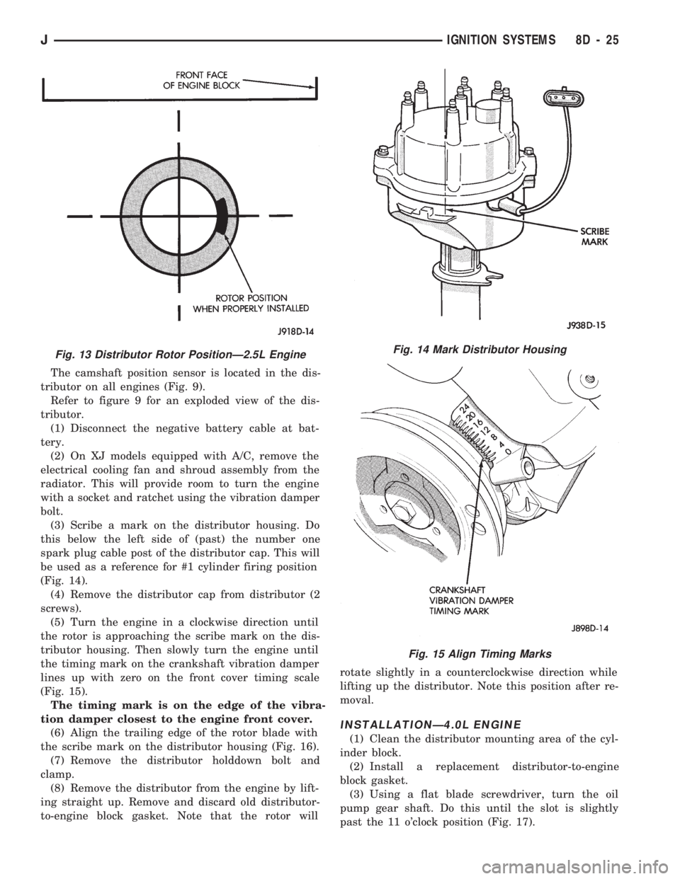
(3) Scribe a mark on the distributor housing. Do
this below the left side of (past) the number one
spark plug cable post of the distributor cap. This will
be used as a reference for #1 cylinder firing position
(Fig. 14).
(4) Remove the distributor cap from distributor (2
screws).
(5) Turn the engine in a clockwise direction until
the rotor is approaching the scribe mark on the dis-
tributor housing. Then slowly turn the engine until
the timing mark on the crankshaft vibration damper
lines up with zero on the front cover timing scale
(Fig. 15).
The timing mark is on the edge of the vibra-
tion damper closest to the engine front cover.
(6) Align the trailing edge of the rotor blade with
the scribe mark on the distributor housing (Fig. 16).
(7) Remove the distributor holddown bolt and
clamp.
(8) Remove the distributor from the engine by lift-
ing straight up. Remove and discard old distributor-
to-engine block gasket. Note that the rotor willrotate slightly in a counterclockwise direction while
lifting up the distributor. Note this position after re-
moval.
INSTALLATIONÐ4.0L ENGINE
(1) Clean the distributor mounting area of the cyl-
inder block.
(2) Install a replacement distributor-to-engine
block gasket.
(3) Using a flat blade screwdriver, turn the oil
pump gear shaft. Do this until the slot is slightly
past the 11 o'clock position (Fig. 17).
Fig. 13 Distributor Rotor PositionÐ2.5L EngineFig. 14 Mark Distributor Housing
Fig. 15 Align Timing Marks
JIGNITION SYSTEMS 8D - 25
Page 339 of 1784
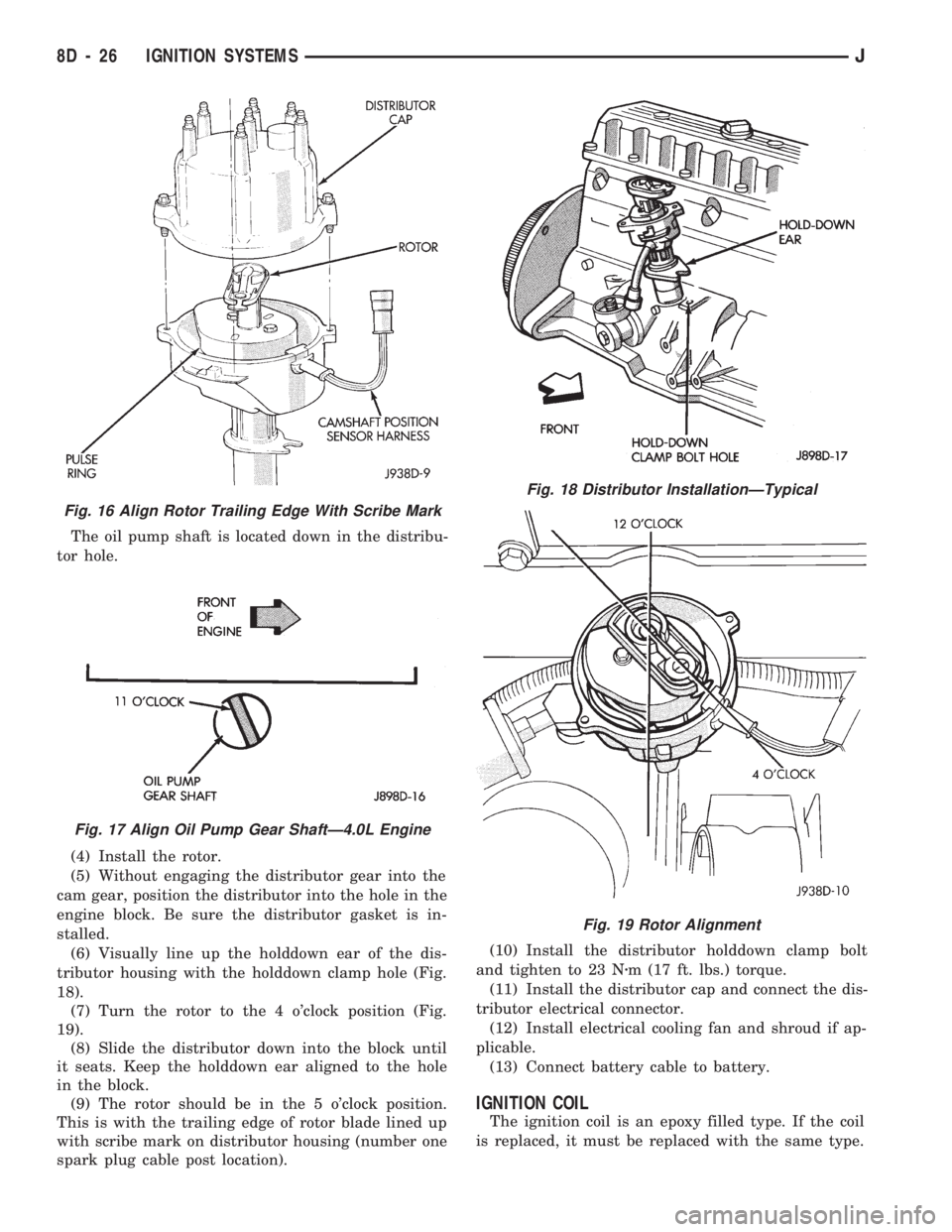
The oil pump shaft is located down in the distribu-
tor hole.
(4) Install the rotor.
(5) Without engaging the distributor gear into the
cam gear, position the distributor into the hole in the
engine block. Be sure the distributor gasket is in-
stalled.
(6) Visually line up the holddown ear of the dis-
tributor housing with the holddown clamp hole (Fig.
18).
(7) Turn the rotor to the 4 o'clock position (Fig.
19).
(8) Slide the distributor down into the block until
it seats. Keep the holddown ear aligned to the hole
in the block.
(9) The rotor should be in the 5 o'clock position.
This is with the trailing edge of rotor blade lined up
with scribe mark on distributor housing (number one
spark plug cable post location).(10) Install the distributor holddown clamp bolt
and tighten to 23 Nzm (17 ft. lbs.) torque.
(11) Install the distributor cap and connect the dis-
tributor electrical connector.
(12) Install electrical cooling fan and shroud if ap-
plicable.
(13) Connect battery cable to battery.
IGNITION COIL
The ignition coil is an epoxy filled type. If the coil
is replaced, it must be replaced with the same type.
Fig. 16 Align Rotor Trailing Edge With Scribe Mark
Fig. 17 Align Oil Pump Gear ShaftÐ4.0L Engine
Fig. 18 Distributor InstallationÐTypical
Fig. 19 Rotor Alignment
8D - 26 IGNITION SYSTEMSJ
Page 341 of 1784
INSTALLATION
(1) Install MAP sensor to dash panel and secure
with mounting nuts.
(2) Install the MAP sensor vacuum supply hose.
(3) Connect the MAP sensor electrical connector.
OXYGEN (O2S) SENSOR
For diagnostics and removal/installation proce-
dures, refer to Group 14, Fuel Systems, in this man-
ual.
POWERTRAIN CONTROL MODULE (PCM)
The PCM was formerly referred to as the SBEC or
engine controller.
XJ MODELS
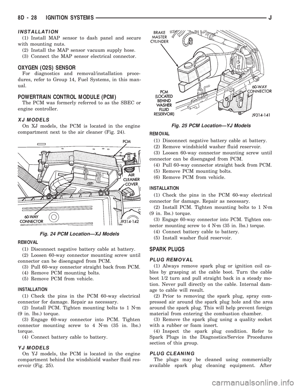
On XJ models, the PCM is located in the engine
compartment next to the air cleaner (Fig. 24).
REMOVAL
(1) Disconnect negative battery cable at battery.
(2) Loosen 60-way connector mounting screw until
connector can be disengaged from PCM.
(3) Pull 60-way connector straight back from PCM.
(4) Remove PCM mounting bolts.
(5) Remove PCM from vehicle.
INSTALLATION
(1) Check the pins in the PCM 60-way electrical
connector for damage. Repair as necessary.
(2) Install PCM. Tighten mounting bolts to 1 Nzm
(9 in. lbs.) torque.
(3) Engage 60-way connector into PCM. Tighten
connector mounting screw to 4 Nzm (35 in. lbs.)
torque.
(4) Connect battery cable to battery.
YJ MODELS
On YJ models, the PCM is located in the engine
compartment behind the windshield washer fluid res-
ervoir (Fig. 25).REMOVAL
(1) Disconnect negative battery cable at battery.
(2) Remove windshield washer fluid reservoir.
(3) Loosen 60-way connector mounting screw until
connector can be disengaged from PCM.
(4) Pull 60-way connector straight back from PCM.
(5) Remove PCM mounting bolts.
(6) Remove PCM from vehicle.
INSTALLATION
(1) Check the pins in the PCM 60-way electrical
connector for damage. Repair as necessary.
(2) Install PCM. Tighten mounting bolts to 1 Nzm
(9 in. lbs.) torque.
(3) Engage 60-way connector into PCM. Tighten con-
nector mounting screw to 4 Nzm (35 in. lbs.) torque.
(4) Connect battery cable to battery.
(5) Install washer fluid reservoir.
SPARK PLUGS
PLUG REMOVAL
(1) Always remove spark plug or ignition coil ca-
bles by grasping at the cable boot. Turn the cable
boot 1/2 turn and pull straight back in a steady mo-
tion. Never pull directly on the cable. Internal dam-
age to cable will result.
(2) Prior to removing the spark plug, spray com-
pressed air around the spark plug hole and the area
around the spark plug. This will help prevent foreign
material from entering the combustion chamber.
(3) Remove the spark plug using a quality socket
with a rubber or foam insert.
(4) Inspect the spark plug condition. Refer to
Spark Plugs in the Diagnostics/Service Procedures
section of this group.
PLUG CLEANING
The plugs may be cleaned using commercially
available spark plug cleaning equipment. After
Fig. 24 PCM LocationÐXJ Models
Fig. 25 PCM LocationÐYJ Models
8D - 28 IGNITION SYSTEMSJ
Page 343 of 1784

IGNITION SWITCH
INDEX
page page
General Information....................... 30
Ignition Switch Installation/Adjustment......... 31Ignition Switch Removal................... 30
Ignition Switch Testing..................... 30
GENERAL INFORMATION
The ignition switch is mounted (under the instru-
ment panel) on the lower section of the steering col-
umn. The headlamp dimmer switch is mounted
beside the ignition switch (Fig. 1). Both of these
switches (ignition and dimmer) share the same
mounting screws.
The switch is connected to the ignition key lock as-
sembly by a remote actuator rod. This remote actua-
tor rod fits into an access hole on the bottom of the
ignition switch (Fig. 2).
IGNITION SWITCH REMOVAL
(1) Disconnect the negative battery cable at the
battery.
(2) XJ models: Remove the lower instrument panel
trim assembly. YJ models: Remove the windshield
wiper intermittent control module and its bracket (if
equipped).
(3) Place the ignition key lock in ACCESSORY po-
sition.
(4) Remove the two headlamp dimmer switch at-
taching nuts. Lift the switch from steering column
while disengaging actuator rod.Before removing dimmer switch, tape the two
remote control actuator rods (ignition switch
and dimmer) to the steering column. This will
prevent accidental disengagement from the up-
per part of the steering column.
(5) Remove the ignition switch-to-steering column
attaching screws.
(6) Disengage the ignition switch from the remote
actuator rod by lifting straight up. Remove switch
from steering column.
(7) Remove wiring from switch as follows:
Two electrical connectors are used to connect all
wiring to the ignition switch. One of the connectors
is installed (interlocked) over the top of the other
connector. Remove wiring from switch by disconnect-
ing the (black) harness connector first and then the
other connector. Remove the switch from the vehicle.
IGNITION SWITCH TESTING
To test the ignition switch circuity and continuity,
proceed as follows. Place the slide bar (on the igni-
tion switch) (Fig. 2) into the detent position to be
tested. An ohmmeter or continuity light may be used
to check switch continuity. Refer to the Ignition
Fig. 1 Ignition Switch/Headlamp Dimmer
SwitchÐTypical
Fig. 2 Ignition Switch/Remote Actuator
RodÐTypical
8D - 30 IGNITION SYSTEMSJ
Page 345 of 1784

taching screws. Do not allow the ignition switch to
move from the ACCESSORY detent position.
Because the ignition switch and the headlamp dim-
mer switch share the same two mounting screws, one
of the screws must be removed from the ignition
switch. This must be doneafterthe ignition switch
has been adjusted andbeforethe dimmer switch has
been installed. Remove one screw.Do notremove
the stud/nut.
(7) Install the headlamp dimmer switch as follows:
Slip switch into actuator rod and position over the ig-
nition switch. Install screws finger tight. Remove the
dimmer switch actuator rod securing-tape from steer-
ing column.
(8) Adjust dimmer switch as follows: Depress the
switch slightly and insert a 3/32-inch drill bit into
the adjustment hole (Fig. 1). This is done to prevent
horizontal switch movement.
(9) Move switch toward steering wheel to remove
any lash from switch actuator rod. Tighten dimmer
and ignition switch fasteners to 4 Nzm (35 in. lbs.)
torque.
(10) XJ models: Install the lower instrument panel
trim assembly. YJ models: Install the windshield
wiper intermittent control module and its bracket (if
equipped).
(11) Install the negative battery cable.
Test dimmer switch. Test ignition switch operation
in all switch positions. If equipped with a tilt steer-
ing column, test operation of dimmer switch and ig-
nition switch in all tilt positions.
Fig. 4 Detent PositionsÐNon-Tilt Steering Column
Fig. 5 Detent PositionsÐTilt Steering Column
8D - 32 IGNITION SYSTEMSJ
Page 348 of 1784

INSTRUMENT PANEL AND GAUGES
GROUP INDEX
page page
INSTRUMENT PANEL AND GAUGESÐXJ..... 1INSTRUMENT PANEL AND GAUGESÐYJ.... 14
INSTRUMENT PANEL AND GAUGESÐXJE
CONTENTS
page page
INSTRUMENT CLUSTER DIAGNOSIS........ 3
INSTRUMENT CLUSTER GENERAL INFORMATION.. 1
INSTRUMENT CLUSTER SERVICE PROCEDURES... 5
SPECIFICATIONS....................... 13
INSTRUMENT CLUSTER GENERAL INFORMATION
INDEX
page page
4WD Indicator Lamp........................ 2
Anti-Lock Brake Indicator Lamp............... 2
Brake Indicator Lamp....................... 2
Coolant Temperature Gauge................. 1
Coolant Temperature Indicator Lamp........... 1
Fuel Gauge.............................. 2
Low Fuel Warning Lamp..................... 2Malfunction Indicator Lamp (Check Engine)...... 2
Oil Pressure Gauge....................... 1
Oil Pressure Indicator Lamp.................. 1
Speedometer/Odometer System.............. 2
Tachometer.............................. 2
Upshift Indicator Lamp...................... 2
Voltmeter............................... 1
With the ignition switch in the ON or START posi-
tion, voltage supplied to the instrument cluster is lim-
ited by fuse #17. The voltage is supplied to all the
gauges and indicator lamps through the instrument
cluster printed circuit.
With the ignition switch in the OFF position, volt-
age is not supplied to the instrument cluster and the
gauges do not indicate any vehicle condition.
VOLTMETER
The voltmeter measures battery or generator out-
put voltage, whichever is greater.
OIL PRESSURE GAUGE
The oil pressure gauge pointer position is controlled
by a magnetic field created by electrical current flow
through the coils within the gauge. A change in current
flow will change the magnetic field which changes the
pointer position. The oil pressure sender is a variable
resistor that changes electrical resistance with a change
in oil pressure (values shown in Specifications chart).
OIL PRESSURE INDICATOR LAMP
Voltage is supplied to one side of the indicator bulb
and the oil pressure switch is connected to the other
side. When oil pressure is too low the switch closes
providing a path to ground, and the indicator bulb
lights.
COOLANT TEMPERATURE GAUGE
The coolant temperature gauge pointer position is
controlled by a magnetic field created by electrical
current flow through the coils within the gauge. A
change in current flow will change the magnetic field
which changes the pointer position. The coolant tem-
perature sensor is a thermistor that changes electri-
cal resistance with a change in coolant temperature
(values shown in Specifications chart).
COOLANT TEMPERATURE INDICATOR LAMP
Voltage is supplied to one side of the indicator bulb
and the coolant temperature switch is connected to the
JINSTRUMENT PANEL AND GAUGES 8E - 1
Page 350 of 1784
INSTRUMENT CLUSTER DIAGNOSIS
INDEX
page page
4WD Indicator Inoperative................... 4
Anti-Lock Indicator......................... 4
Brake Indicator Inoperative.................. 4
Coolant Temperature Gauge Inoperative........ 3
Coolant Temperature Indicator Inoperative....... 3
Fuel Gauge Inoperative..................... 3
Gauges and Indicators Inoperative............ 3
Instrument Panel Lamps.................... 4
Low Fuel Warning Inoperative................ 4
Low Washer Indicator Inoperative............. 4Malfunction Indicator Lamp (Check Engine)...... 4
Oil Pressure Gauge Inoperative............... 3
Oil Pressure Indicator Inoperative............. 3
Radio/Clock Illumination.................... 4
Seat Belt Indicator........................ 4
Speedomete/Odometer Inoperative............. 3
Tachometer Inoperative..................... 3
Upshift Indicator Inoperative................. 4
Voltmeter Inoperative....................... 3
SPEEDOMETER/ODOMETER INOPERATIVE
(1) Check for continuity in the wire between the
vehicle speed sensor and cluster connector pin A5.
(2) With the ignition switch in the ON position,
check for battery voltage across pin A8 (B+) and pin
B2 (ground).
(3) Perform vehicle speed sensor test. Refer to the
appropriate vehicle Diagnostic Test Procedures man-
ual.
(4) If all the previous tests prove good, replace
speedometer/odometer.
GAUGES AND INDICATORS INOPERATIVE
(1) Remove and inspect fuse #17. Replace as re-
quired.
(2) Measure resistance at instrument cluster con-
nector terminal A3. Meter should read zero ohms. If
not, repair open to ground.
VOLTMETER INOPERATIVE
(1) Turn ignition switch to ON. Voltmeter should
read battery voltage. If not, go to step 2.
(2) Measure voltage at instrument cluster connec-
tor terminal A8. Meter should read battery voltage.
If OK, replace meter. If not, repair open to fuse #17.
OIL PRESSURE GAUGE INOPERATIVE
(1) Turn ignition switch to ON.
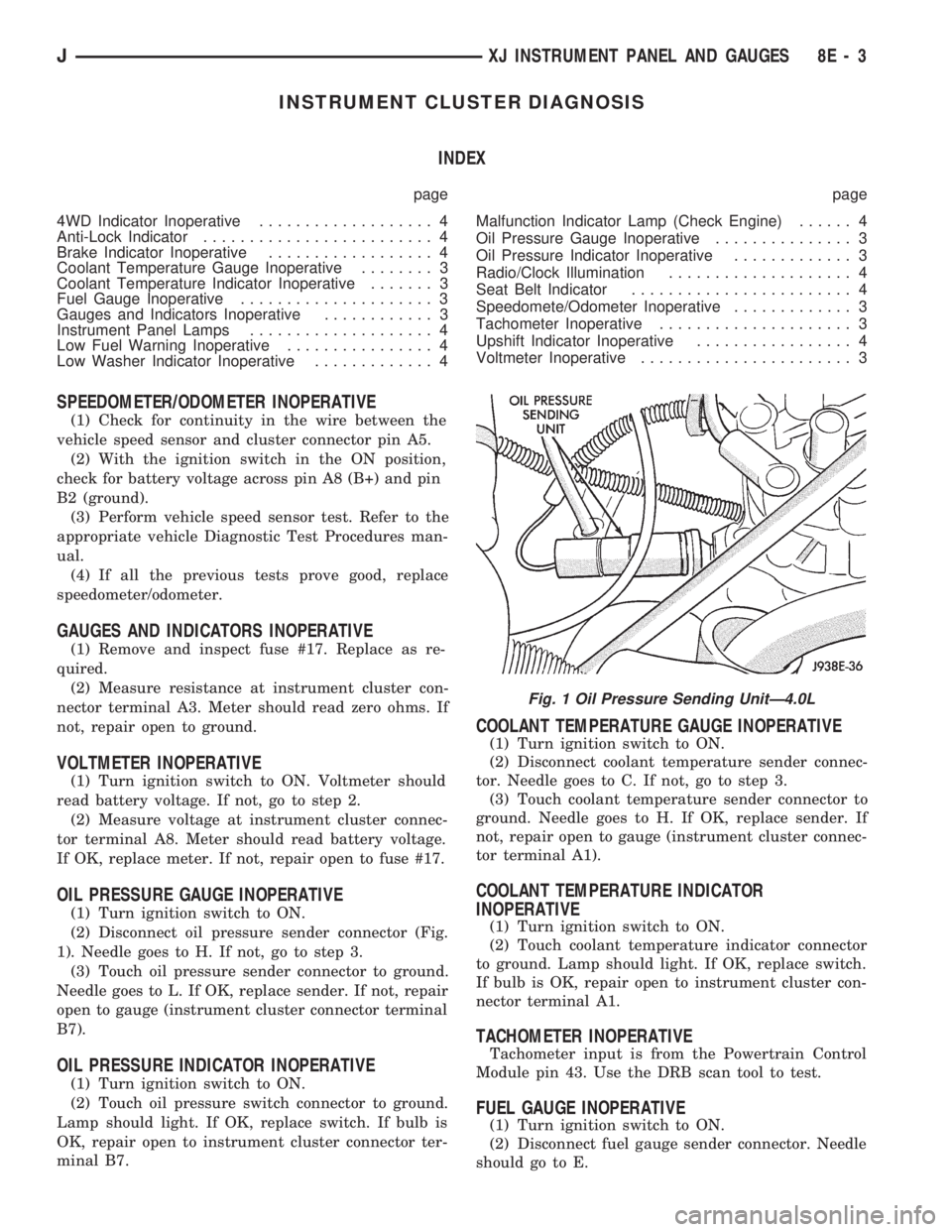
(2) Disconnect oil pressure sender connector (Fig.
1). Needle goes to H. If not, go to step 3.
(3) Touch oil pressure sender connector to ground.
Needle goes to L. If OK, replace sender. If not, repair
open to gauge (instrument cluster connector terminal
B7).
OIL PRESSURE INDICATOR INOPERATIVE
(1) Turn ignition switch to ON.
(2) Touch oil pressure switch connector to ground.
Lamp should light. If OK, replace switch. If bulb is
OK, repair open to instrument cluster connector ter-
minal B7.
COOLANT TEMPERATURE GAUGE INOPERATIVE
(1) Turn ignition switch to ON.
(2) Disconnect coolant temperature sender connec-
tor. Needle goes to C. If not, go to step 3.
(3) Touch coolant temperature sender connector to
ground. Needle goes to H. If OK, replace sender. If
not, repair open to gauge (instrument cluster connec-
tor terminal A1).
COOLANT TEMPERATURE INDICATOR
INOPERATIVE
(1) Turn ignition switch to ON.
(2) Touch coolant temperature indicator connector
to ground. Lamp should light. If OK, replace switch.
If bulb is OK, repair open to instrument cluster con-
nector terminal A1.
TACHOMETER INOPERATIVE
Tachometer input is from the Powertrain Control
Module pin 43. Use the DRB scan tool to test.
FUEL GAUGE INOPERATIVE
(1) Turn ignition switch to ON.
(2) Disconnect fuel gauge sender connector. Needle
should go to E.
Fig. 1 Oil Pressure Sending UnitÐ4.0L
JXJ INSTRUMENT PANEL AND GAUGES 8E - 3