1994 JEEP CHEROKEE battery
[x] Cancel search: batteryPage 369 of 1784

GAUGE PACKAGE GENERAL INFORMATION
The gauge package contains 4 gauges and the 4
wheel drive indicator. The gauges have a common
battery feed from fuse #9 and ignition switch. Al-
though they have separate power sources, the 4
gauges share a common ground connection.
The voltmeter indicates electrical system voltage.
When the engine is not running, the voltage regis-
tered is from the battery. After the engine is started,
charging system voltage is indicated. In the gauge
package, the voltmeter forms a parallel connectionacross the battery feed and ground.
The remaining gauges - oil pressure, fuel and cool-
ant temperature - are connected to individual sender
units. Variable resistors in the senders will change
the amount of current allowed to flow through the
gauge coils. As current flow through the coils varies,
the position of the indicator needle also will vary.
The 4 gauges are connected to battery feed, ground
and the sender units through a printed circuit
mounted on the back of the gauge housing.
GAUGE PACKAGE DIAGNOSIS
ALL GAUGES INOPERATIVE (Fig. 15)
(1) Check the fuse #9. Replace as required.
(2) Turn ignition switch to ON and measure volt-
age at battery side of fuse #9. Meter should read bat-
tery voltage. If not, repair open from ignition switch.
(3) Unplug gauge package connector from gauge
package.
(4) Turn ignition switch to OFF and measure resis-
tance from instrument cluster connector terminals 1
and 13 to a clean chassis ground. Meter should read
zero ohms. If not, repair open to ground.
(5) Turn ignition switch to ON and measure volt-
age at instrument cluster connector terminals 2 and
12. Meter should read battery voltage. If not, repair
open from fuse panel.
ONE GAUGE INOPERATIVE
Does not apply to voltmeter.
OIL PRESSURE SENDER
(1) Turn ignition switch to ON.
(2) Unplug oil pressure sender connector from oil
pressure sender.
(3) Touch connector to engine block (ground).
Gauge should read at low end of scale.
(4) When connector is NOT touching ground (open
circuit) gauge should read at high end of scale. If OK
replace sender. If not, proceed with step 5.
(5) Check circuit between sender and gauge for an
open. Repair as required. If wiring is OK, replace
gauge.
COOLANT TEMPERATURE SENDER
(1) Turn ignition switch to ON.
(2) Unplug coolant temperature sender connector
from coolant temperature sender.
(3) Touch connector to engine block (ground).
Gauge should read at high end of scale.
(4) When connector is NOT touching ground (open
circuit) gauge should read at low end of scale. If OK
replace sender. If not, proceed with step 5.
(5) Check circuit between sender and gauge for an
open. Repair as required. If wiring is OK, replace
gauge.
FUEL GAUGE SENDER
(1) Turn ignition switch to ON.
(2) Separate fuel gauge sender connector from fuel
gauge sender near tank.
(3) Ground the center wire of the body harness
side of the connector. The gauge should read at low
end of scale. If OK, check sending unit (step 4). If
not, check circuit between connector and gauge. Re-
pair as required. If circuit is OK, replace gauge.
(4) Turn ignition switch to OFF.
(5) Measure resistance from fuel gauge sender con-
nector center terminal to a clean chassis ground.
Meter readings should correspond to those shown in
Specifications. If not OK, replace sender. If OK, re-
pair open from fuel gauge sender connector to
ground.
PRINTED CIRCUIT
(1) Turn ignition switch to ON.
(2) Unplug gauge package connector from gauge
package.
(3) Measure resistance from gauge package termi-
nal 12 (fuel and coolant temperature gauge) or from
terminal 2 (voltmeter and oil pressure gauge) to
gauge battery terminal. Meter should read zero
ohms. If not, replace/repair printed circuit.
(4) Measure resistance from gauge package termi-
nal 13 (fuel and coolant temperature gauge) or from
terminal 1 (voltmeter and oil pressure gauge) to
gauge ground terminal. Meter should read zero
ohms. If not, replace/repair printed circuit. If zero
ohms, replace gauge.
GAUGE CALIBRATION VALUES
Use the charts in Specifications. The calibration of
the gauge can be checked. If the indicator needle is
not in the correct position, replace the gauge.
4WD INDICATOR
The four-wheel drive indicator lamp circuit is com-
pleted by the Command-Trac switch located below
the battery.
8E - 22 YJ INSTRUMENT PANEL AND GAUGESJ
Page 376 of 1784
AUDIO SYSTEMS
CONTENTS
page page
GENERAL INFORMATION.................. 1
RADIO ANTENNA........................ 8XJ SERVICE PROCEDURES................ 4
YJ SERVICE PROCEDURES................ 6
GENERAL INFORMATION
DESCRIPTION
Each radio receives ignition feed from an ignition
switch controlled fuse. There is an additional in-line
fuse in the back of the radio chassis. The in-line fuse
will blow in the event an internal short occurs.
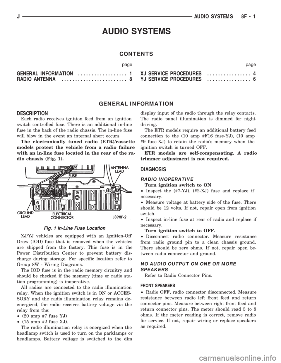
The electronically tuned radio (ETR)/cassette
models protect the vehicle from a radio failure
with an in-line fuse located in the rear of the ra-
dio chassis (Fig. 1).
XJ/YJ vehicles are equipped with an Ignition-Off
Draw (IOD) fuse that is removed when the vehicles
are shipped from the factory. This fuse is in the
Power Distribution Center to prevent battery dis-
charge during storage. For specific location refer to
Group 8W - Wiring Diagrams.
The IOD fuse is in the radio memory circuitry and
should be checked if the memory (time or radio sta-
tion programming) is inoperative.
All radios are connected to the radio illumination
relay. When the ignition switch is in ON or ACCES-
SORY and the radio illumination relay remains de-
energized, the radio receives battery voltage via the
relay from the:
²(20 amp #7 fuse YJ)
²(15 amp #2 fuse XJ).
The radio illumination relay is energized when the
headlamp switch is used to turn on the parklamps or
headlamps. Battery voltage is switched to the dimdisplay input of the radio through the relay contacts.
The radio panel illumination is dimmed for night
driving.
The ETR models require an additional battery feed
connection to the (10 amp #F16 fuse-YJ), (10 amp
#9 fuse-XJ) to retain the radio's memory when the
ignition switch is turned OFF.
ETR models are self-compensating. A radio
trimmer adjustment is not required.
DIAGNOSIS
RADIO INOPERATIVE
Turn ignition switch to ON
²Inspect the (#7-YJ), (#2-XJ) fuse and replace if
necessary.
²Measure voltage at battery side of the fuse. There
should be 12 volts. If not, repair open from ignition
switch.
²Inspect in-line fuse at rear of radio and replace if
necessary.
Turn ignition switch to OFF.
²Disconnect radio connector. Measure resistance
from radio ground pin to a clean chassis ground.
There should be zero ohms. If not, repair open be-
tween radio connector and ground.
NO AUDIO OUTPUT ON ONE OR MORE
SPEAKERS
Refer to Radio Connector Pins.
FRONT SPEAKERS
²Radio OFF, radio connector disconnected. Measure
resistance between radio left front feed and return
connector pins. Measure between right front feed and
return connector pins. The meter should read 5 to 8
ohms. If the meter reading is correct, remove radio
for service. If not, repair wiring or replace speakers
as required.
Fig. 1 In-Line Fuse Location
JAUDIO SYSTEMS 8F - 1
Page 377 of 1784
REAR SPEAKERS
²Radio OFF, radio connector disconnected. Measure
resistance between radio left rear feed and return
connector pins. Measure between right rear feed and
return connector pins. The meter should read 5 to 8
ohms. If meter reading is correct remove radio for
service. If not, repair wiring or replace speakers as
required.
DISTORTED AUDIO OUTPUT ON ONE OR
MORE SPEAKERS
²With the radio ON, substitute known good speaker
or speakers. If the sound is still distorted, remove ra-
dio for service.
WEAK OR NO RECEPTION; NO AUDIO
OUTPUT; BACKGROUND NOISE PRESENT
Ignition switch in ON, radio ON.
²Inspect antenna cable and connector at radio and
tighten or repair as necessary.
²Unplug coax cable and connectors from radio. Mea-
sure resistance from center conductor to coaxial
shield. The meter should read infinite resistance
(open). If it does not, replace antenna assembly.
²Measure resistance of antenna mast to tip of cen-
ter conductor at radio end of cable. The meter should
read 0 to 0.5 ohms. If it does not, replace lead-in ca-
ble or antenna assembly.
²Measure resistance from coaxial shield to chassis
ground (vehicle body). The meter should read zero
ohms. If it does not, ground antenna base to vehicle
body, or replace antenna assembly as required
For all problems with no or low audio output
not resolved by these tests, remove radio for ser-
vice.
MEMORY DOES NOT OPERATE
²Inspect (F16 in Power Distribution Center-YJ),
(#9 in Fuse Panel-XJ) fuse and replace if necessary.
²Measure voltage at battery side of previously ref-
erenced fuse. There should be 12 volts at battery side
of fuse. If not, check the Maxi fuse.
Refer to Group 8W - Wiring Diagrams.
²Measure voltage at radio connector pin 4. There
should be 12 volts. If meter reading is correct, re-
move radio for service. If not, repair open from fuse.
RADIO DISPLAY ILLUMINATION (PARKLAMPS
AND HEADLAMPS OPERATING NORMALLY)
Headlamp switch OFF, radio ON.
²Measure voltage at radio connector pin 10. There
should be 12 volts. If not, go to next step. If OK, re-
move radio for repair by authorized outlet.
²Measure voltage at illumination relay pin 3. There
should be 12 volts. If 12 volts present, replace illumi-
nation relay. If not, repair open in circuit.RADIO DISPLAY ILLUMINATION DIMMING CIRCUIT
Turn headlamp switch to PARKLAMPS for
voltage tests; turn headlamp switch to OFF for
resistance tests.
²Separate relay connector from radio illumination
relay. Measure resistance from relay connector pin 2
to a clean chassis ground. The meter should read
zero ohms. If not, repair open between relay connec-
tor and ground.
²Measure voltage at radio illumination relay pin 5.
There should be battery voltage. If not repair open
from headlamp switch.
²Measure voltage at radio illumination relay pin 4.
Voltage should vary with dimmer switch. If OK, go
to next step. If not, repair open circuit between pin 4
and interior lamp rheostat.
²Measure voltage at radio illumination relay pin
10. Voltage should vary with dimmer switch. If OK,
remove radio for repair by authorized outlet. If not,
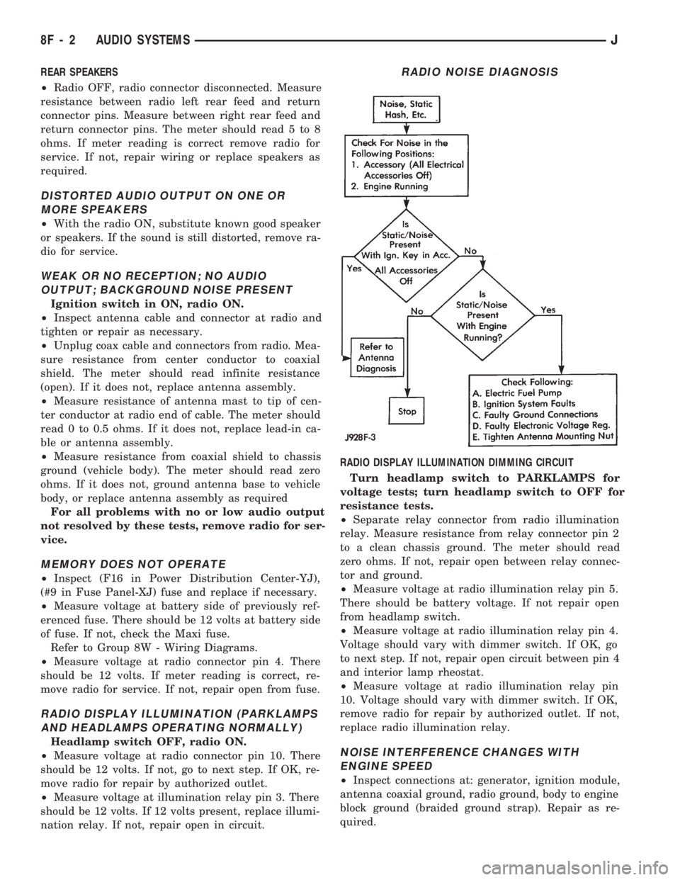
replace radio illumination relay.NOISE INTERFERENCE CHANGES WITH
ENGINE SPEED
²Inspect connections at: generator, ignition module,
antenna coaxial ground, radio ground, body to engine
block ground (braided ground strap). Repair as re-
quired.
RADIO NOISE DIAGNOSIS
8F - 2 AUDIO SYSTEMSJ
Page 379 of 1784
XJ SERVICE PROCEDURES
RADIO REPLACEMENT
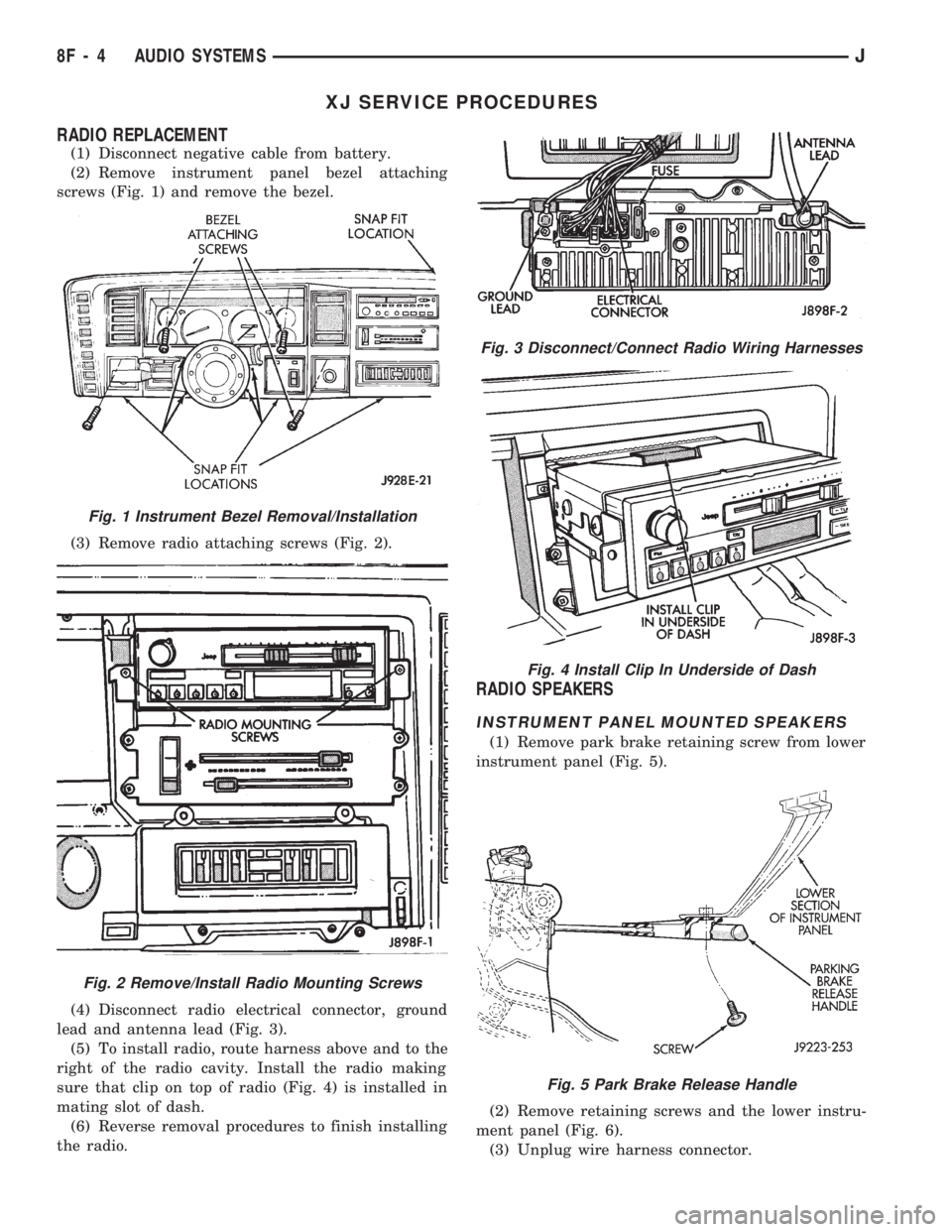
(1) Disconnect negative cable from battery.
(2) Remove instrument panel bezel attaching
screws (Fig. 1) and remove the bezel.
(3) Remove radio attaching screws (Fig. 2).
(4) Disconnect radio electrical connector, ground
lead and antenna lead (Fig. 3).
(5) To install radio, route harness above and to the
right of the radio cavity. Install the radio making
sure that clip on top of radio (Fig. 4) is installed in
mating slot of dash.
(6) Reverse removal procedures to finish installing
the radio.
RADIO SPEAKERS
INSTRUMENT PANEL MOUNTED SPEAKERS
(1) Remove park brake retaining screw from lower
instrument panel (Fig. 5).
(2) Remove retaining screws and the lower instru-
ment panel (Fig. 6).
(3) Unplug wire harness connector.
Fig. 3 Disconnect/Connect Radio Wiring Harnesses
Fig. 4 Install Clip In Underside of Dash
Fig. 5 Park Brake Release Handle
Fig. 1 Instrument Bezel Removal/Installation
Fig. 2 Remove/Install Radio Mounting Screws
8F - 4 AUDIO SYSTEMSJ
Page 381 of 1784
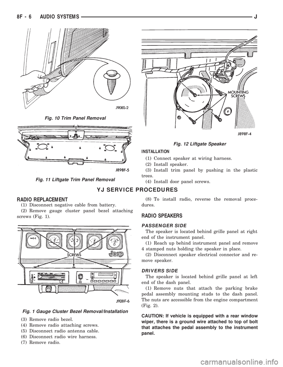
INSTALLATION
(1) Connect speaker at wiring harness.
(2) Install speaker.
(3) Install trim panel by pushing in the plastic
trees.
(4) Install door panel screws.
YJ SERVICE PROCEDURES
RADIO REPLACEMENT
(1) Disconnect negative cable from battery.
(2) Remove gauge cluster panel bezel attaching
screws (Fig. 1).
(3) Remove radio bezel.
(4) Remove radio attaching screws.
(5) Disconnect radio antenna cable.
(6) Disconnect radio wire harness.
(7) Remove radio.(8) To install radio, reverse the removal proce-
dures.
RADIO SPEAKERS
PASSENGER SIDE
The speaker is located behind grille panel at right
end of the instrument panel.
(1) Reach up behind instrument panel and remove
4 stamped nuts holding the speaker in place.
(2) Disconnect speaker electrical connector and re-
move speaker.
DRIVERS SIDE
The speaker is located behind grille panel at left
end of the dash panel.
(1) Remove nuts that attach the parking brake
pedal assembly mounting studs to the dash panel.
The nuts are accessible from the engine compartment
(Fig. 2).
CAUTION: If vehicle is equipped with a rear window
wiper, there is a ground wire attached to top of bolt
that attaches the pedal assembly to the instrument
panel.
Fig. 10 Trim Panel Removal
Fig. 11 Liftgate Trim Panel Removal
Fig. 12 Liftgate Speaker
Fig. 1 Gauge Cluster Bezel Removal/Installation
8F - 6 AUDIO SYSTEMSJ
Page 384 of 1784
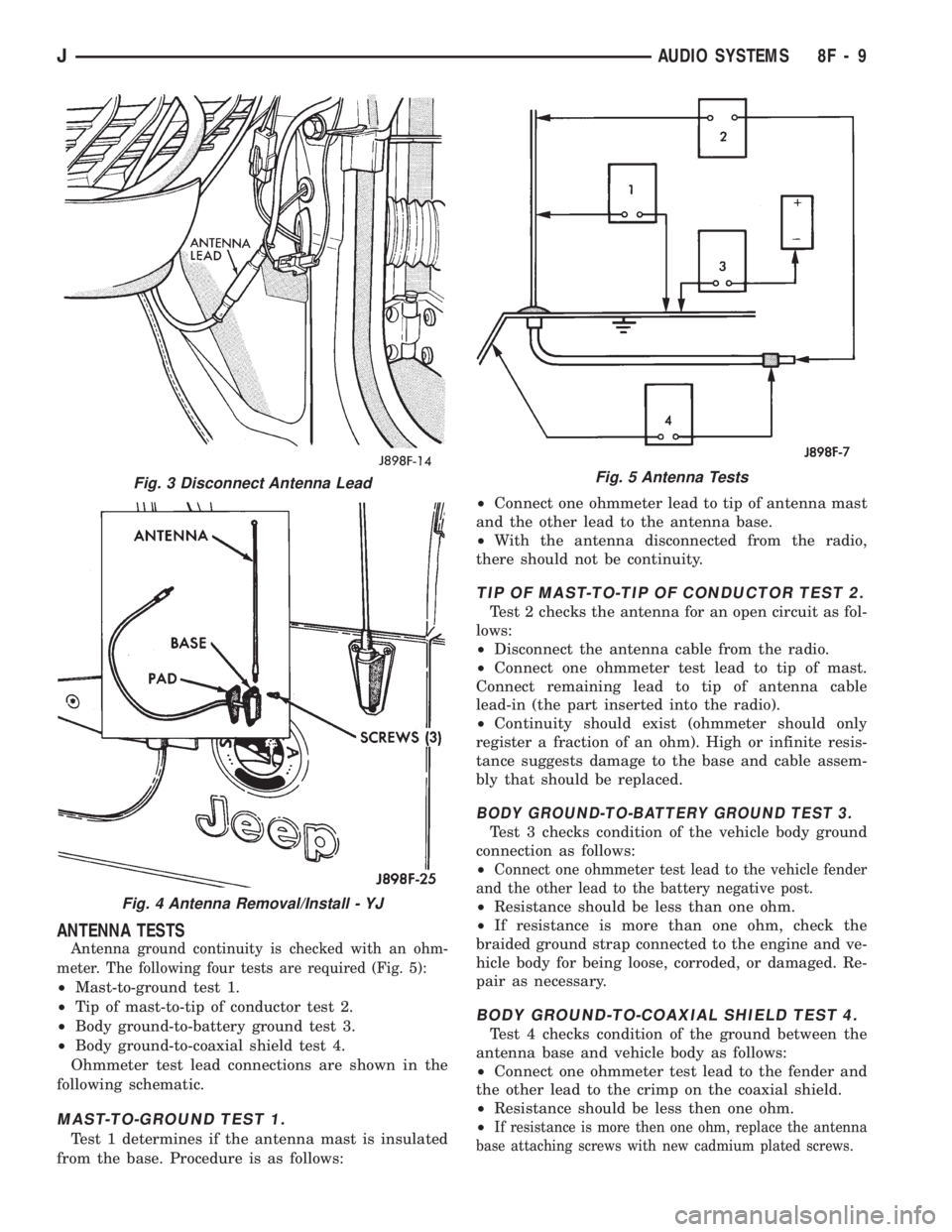
ANTENNA TESTS
Antenna ground continuity is checked with an ohm-
meter. The following four tests are required (Fig. 5):
²Mast-to-ground test 1.
²Tip of mast-to-tip of conductor test 2.
²Body ground-to-battery ground test 3.
²Body ground-to-coaxial shield test 4.
Ohmmeter test lead connections are shown in the
following schematic.
MAST-TO-GROUND TEST 1.
Test 1 determines if the antenna mast is insulated
from the base. Procedure is as follows:²Connect one ohmmeter lead to tip of antenna mast
and the other lead to the antenna base.
²With the antenna disconnected from the radio,
there should not be continuity.
TIP OF MAST-TO-TIP OF CONDUCTOR TEST 2.
Test 2 checks the antenna for an open circuit as fol-
lows:
²Disconnect the antenna cable from the radio.
²Connect one ohmmeter test lead to tip of mast.
Connect remaining lead to tip of antenna cable
lead-in (the part inserted into the radio).
²Continuity should exist (ohmmeter should only
register a fraction of an ohm). High or infinite resis-
tance suggests damage to the base and cable assem-
bly that should be replaced.
BODY GROUND-TO-BATTERY GROUND TEST 3.
Test 3 checks condition of the vehicle body ground
connection as follows:
²
Connect one ohmmeter test lead to the vehicle fender
and the other lead to the battery negative post.
²Resistance should be less than one ohm.
²If resistance is more than one ohm, check the
braided ground strap connected to the engine and ve-
hicle body for being loose, corroded, or damaged. Re-
pair as necessary.
BODY GROUND-TO-COAXIAL SHIELD TEST 4.
Test 4 checks condition of the ground between the
antenna base and vehicle body as follows:
²Connect one ohmmeter test lead to the fender and
the other lead to the crimp on the coaxial shield.
²Resistance should be less then one ohm.
²
If resistance is more then one ohm, replace the antenna
base attaching screws with new cadmium plated screws.
Fig. 3 Disconnect Antenna Lead
Fig. 4 Antenna Removal/Install - YJ
Fig. 5 Antenna Tests
JAUDIO SYSTEMS 8F - 9
Page 386 of 1784
HORNS
CONTENTS
page page
GENERAL INFORMATION.................. 1
HORN SWITCH (HORN PAD) REPLACEMENT . . 3
TORQUE SPECIFICATIONS................. 3XJ ..................................... 1
YJ ..................................... 2
GENERAL INFORMATION
For XJ/YJ vehicles battery voltage is applied to the
horn relay through a fuse.
When the horn switch is depressed, the horn relay
is grounded, pulling the contact closed and providing
battery voltage to the horns.
A slip ring and brush arrangement in the steering
wheel allows the switch circuit to maintain contact
while allowing rotation of the steering wheel.On XJ models, a cadmium-plated ground
screw is used to attach the horn(s) to the body.
Do not substitute other types of ground screws
as they may become corroded and cause a loss
of ground.
XJ
REPLACEMENT
(1) Raise and support the vehicle.
(2) Remove the splash shield.
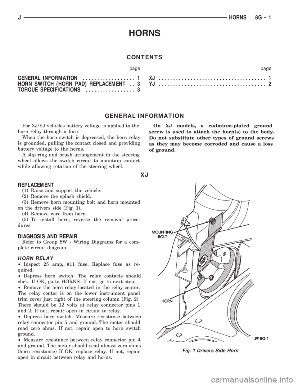
(3) Remove horn mounting bolt and horn mounted
on the drivers side (Fig. 1).
(4) Remove wire from horn.
(5) To install horn, reverse the removal proce-
dures.
DIAGNOSIS AND REPAIR
Refer to Group 8W - Wiring Diagrams for a com-
plete circuit diagram.
HORN RELAY
²Inspect 25 amp, #11 fuse. Replace fuse as re-
quired.
²Depress horn switch. The relay contacts should
click. If OK, go to HORNS. If not, go to next step.
²Remove the horn relay located in the relay center.
The relay center is on the lower instrument panel
trim cover just right of the steering column (Fig. 2).
There should be 12 volts at relay connector pins 1
and 2. If not, repair open in circuit to relay.
²Depress horn switch. Measure resistance between
relay connector pin 5 and ground. The meter should
read zero ohms. If not, repair open to horn switch
ground.
²Measure resistance between relay connector pin 4
and ground. The meter should read almost zero ohms
(horn resistance) If OK, replace relay. If not, repair
open in circuit between relay and horns.
Fig. 1 Drivers Side Horn
JHORNS 8G - 1
Page 388 of 1784
HORN SWITCH (HORN PAD) REPLACEMENT
(1) Disconnect negative cable from battery.
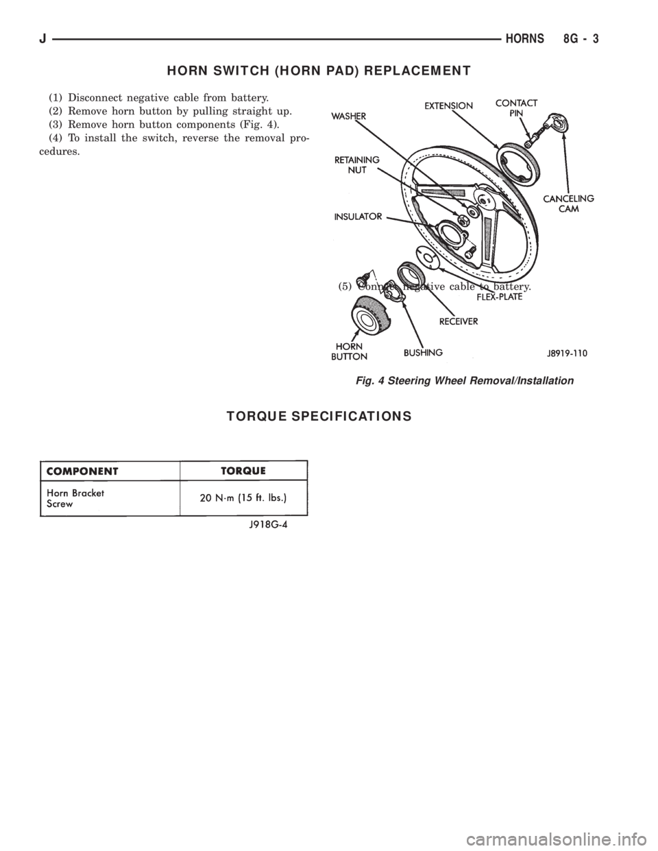
(2) Remove horn button by pulling straight up.
(3) Remove horn button components (Fig. 4).
(4) To install the switch, reverse the removal pro-
cedures.
(5) Connect negative cable to battery.
TORQUE SPECIFICATIONS
Fig. 4 Steering Wheel Removal/Installation
JHORNS 8G - 3