1994 JEEP CHEROKEE battery
[x] Cancel search: batteryPage 285 of 1784
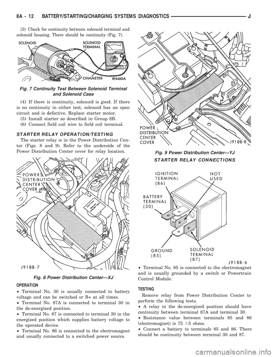
(3) Check for continuity between solenoid terminal and
solenoid housing. There should be continuity (Fig. 7).
(4) If there is continuity, solenoid is good. If there
is no continuity in either test, solenoid has an open
circuit and is defective. Replace starter motor.
(5) Install starter as described in Group 8B.
(6) Connect field coil wire to field coil terminal.
STARTER RELAY OPERATION/TESTING
The starter relay is in the Power Distribution Cen-
ter (Figs. 8 and 9). Refer to the underside of the
Power Distribution Center cover for relay location.
OPERATION
²Terminal No. 30 is usually connected to battery
voltage and can be switched or B+ at all times.
²Terminal No. 87A is connected to terminal 30 in
the de-energized position.
²Terminal No. 87 is connected to terminal 30 in the
energized position which supplies battery voltage to
the operated device.
²Terminal No. 86 is connected to the electromagnet
and usually connected to a switched power source.²Terminal No. 85 is connected to the electromagnet
and is usually grounded by a switch or Powertrain
Control Module.
TESTING
Remove relay from Power Distribution Center to
perform the following tests.
²A relay in the de-energized position should have
continuity between terminal 87A and terminal 30.
²Resistance value between terminals 85 and 86
(electromagnet) is 7565 ohms.
²Connect a battery to terminals 85 and 86. There
should be continuity between terminal 30 and 87.
Fig. 9 Power Distribution CenterÐYJ
STARTER RELAY CONNECTIONS
Fig. 7 Continuity Test Between Solenoid Terminal
and Solenoid Case
Fig. 8 Power Distribution CenterÐXJ
8A - 12 BATTERY/STARTING/CHARGING SYSTEMS DIAGNOSTICSJ
Page 286 of 1784
IGNITION SWITCH TEST
After testing starter solenoid and relay and they
check out OK, trouble is probably with ignition
switch or its wiring.
Check all wiring for opens and shorts, and connec-
tions for being loose or corroded.
PARK/NEUTRAL POSITION SWITCH
Refer to Group 21 - Transmissions for diagnostic
information.
2.5L STARTER MOTOR NOISE DIAGNOSIS
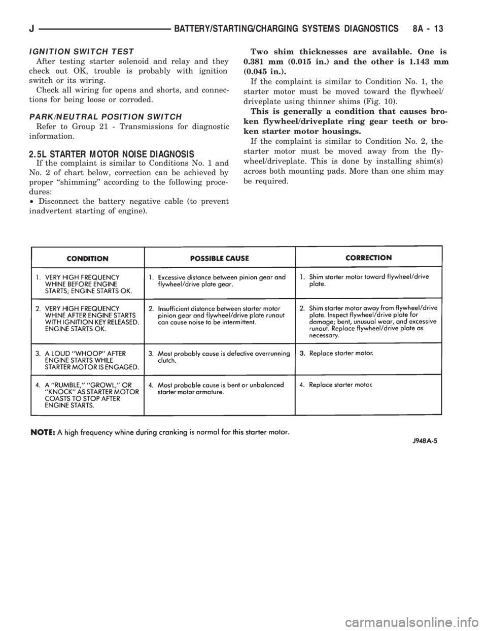
If the complaint is similar to Conditions No. 1 and
No. 2 of chart below, correction can be achieved by
proper ``shimming'' according to the following proce-
dures:
²Disconnect the battery negative cable (to prevent
inadvertent starting of engine).Two shim thicknesses are available. One is
0.381 mm (0.015 in.) and the other is 1.143 mm
(0.045 in.).
If the complaint is similar to Condition No. 1, the
starter motor must be moved toward the flywheel/
driveplate using thinner shims (Fig. 10).
This is generally a condition that causes bro-
ken flywheel/driveplate ring gear teeth or bro-
ken starter motor housings.
If the complaint is similar to Condition No. 2, the
starter motor must be moved away from the fly-
wheel/driveplate. This is done by installing shim(s)
across both mounting pads. More than one shim may
be required.
JBATTERY/STARTING/CHARGING SYSTEMS DIAGNOSTICS 8A - 13
Page 287 of 1784
GENERATOR TEST PROCEDURES ON VEHICLE
INDEX
page page
Diagnostic Procedures..................... 15
General Information....................... 14Operational Check with Battery Indicator
(Base Cluster Only)..................... 14
Operational Check with Voltmeter............ 15
GENERAL INFORMATION
The generator is belt-driven by the engine. All en-
gines use serpentine drive.
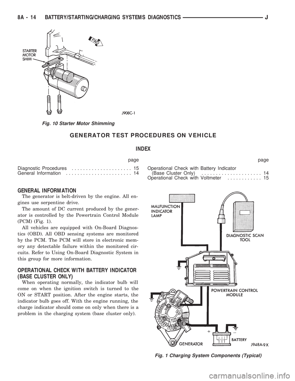
The amount of DC current produced by the gener-
ator is controlled by the Powertrain Control Module
(PCM) (Fig. 1).
All vehicles are equipped with On-Board Diagnos-
tics (OBD). All OBD sensing systems are monitored
by the PCM. The PCM will store in electronic mem-
ory any detectable failure within the monitored cir-
cuits. Refer to Using On-Board Diagnostic System in
this group for more information.
OPERATIONAL CHECK WITH BATTERY INDICATOR
(BASE CLUSTER ONLY)
When operating normally, the indicator bulb will
come on when the ignition switch is turned to the
ON or START position. After the engine starts, the
indicator bulb goes off. With the engine running, the
charge indicator should come on only when there is a
problem in the charging system (base cluster only).
Fig. 10 Starter Motor Shimming
Fig. 1 Charging System Components (Typical)
8A - 14 BATTERY/STARTING/CHARGING SYSTEMS DIAGNOSTICSJ
Page 288 of 1784

OPERATIONAL CHECK WITH VOLTMETER
When the ignition switch is turned to the ON po-
sition, battery potential will register on the voltme-
ter. During engine cranking a lower voltage will
appear on the meter. With the engine running, a
voltage reading higher than the first reading (igni-
tion in ON) should register.
DIAGNOSTIC PROCEDURES
If the indicator operates abnormally, or if an un-
dercharged or overcharged battery condition occurs,
the following procedures may be used to diagnose the
charging system.
Remember that an undercharged battery is often
caused by:
²accessories being left on overnight
²or by a defective switch which allows a bulb, such
as a liftgate or glove box light, to stay on (refer to
Ignition Off Draw Diagnosis).
VISUAL INSPECTION
²Inspect condition of battery cable terminals, bat-
tery posts, connections at engine block, starter motor
solenoid and relay. They should be clean and tight.
Repair as required.
²Inspect all fuses in the fuse block for tightness in
receptacles. They should be properly installed and
tight. Repair or replace as required.²Inspect the electrolyte level in the battery and add
water if necessary.
²Inspect generator mounting bolts for tightness. Re-
place or torque bolt as required. Refer to Torque
Specifications in Battery/Starter/Generator Service.
²Inspect generator drive belt condition and tension.
Tension or replace belt as required. Refer to Belt
Tension Specifications in Battery/Starter/Generator
Service.
²Inspect connection at generator B+ output. It
should be clean and tight. Repair as required.
GENERATOR OUTPUT WIRE RESISTANCE
TEST
Generator output wire resistance test will show
amount of voltage drop across generator output wire
between generator battery terminal and battery pos-
itive post.
PREPARATION
(1) Before starting test make sure vehicle has a
fully charged battery. Test and procedures on how to
check for a fully charged battery are shown in Bat-
tery Test Procedures.
(2) Turn OFF ignition switch.
(3) Disconnect negative cable from battery.
(4) Disconnect generator output wire from genera-
tor output battery terminal.
Fig. 2 Generator Output Wire Resistance Test (Typical)
JBATTERY/STARTING/CHARGING SYSTEMS DIAGNOSTICS 8A - 15
Page 289 of 1784
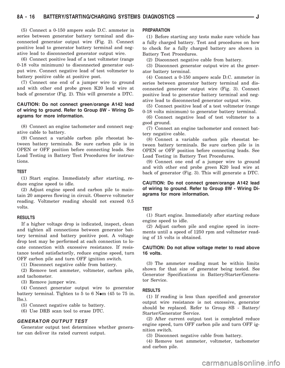
(5) Connect a 0-150 ampere scale D.C. ammeter in
series between generator battery terminal and dis-
connected generator output wire (Fig. 2). Connect
positive lead to generator battery terminal and neg-
ative lead to disconnected generator output wire.
(6) Connect positive lead of a test voltmeter (range
0-18 volts minimum) to disconnected generator out-
put wire. Connect negative lead of test voltmeter to
battery positive cable at positive post.
(7) Connect one end of a jumper wire to ground
and with other end probe green K20 lead wire at
back of generator (Fig. 2). This will generate a DTC.
CAUTION: Do not connect green/orange A142 lead
of wiring to ground. Refer to Group 8W - Wiring Di-
agrams for more information.
(8) Connect an engine tachometer and connect neg-
ative cable to battery.
(9) Connect a variable carbon pile rheostat be-
tween battery terminals. Be sure carbon pile is in
OPEN or OFF position before connecting leads. See
Load Testing in Battery Test Procedures for instruc-
tions.
TEST
(1) Start engine. Immediately after starting, re-
duce engine speed to idle.
(2) Adjust engine speed and carbon pile to main-
tain 20 amperes flowing in circuit. Observe voltmeter
reading. Voltmeter reading should not exceed 0.5
volts.
RESULTS
If a higher voltage drop is indicated, inspect, clean
and tighten all connections between generator bat-
tery terminal and battery positive post. A voltage
drop test may be performed at each connection to lo-
cate connection with excessive resistance. If resis-
tance tested satisfactorily, reduce engine speed, turn
OFF carbon pile and turn OFF ignition switch.
(1) Disconnect negative cable from battery.
(2) Remove test ammeter, voltmeter, carbon pile,
and tachometer.
(3) Remove jumper wire.
(4) Connect generator output wire to generator
battery terminal. Tighten to 5 to 6 NIm (45 to 75 in.
lbs.).
(5) Connect negative cable to battery.
(6) Use DRB scan tool to erase DTC.
GENERATOR OUTPUT TEST
Generator output test determines whether genera-
tor can deliver its rated current output.PREPARATION
(1) Before starting any tests make sure vehicle has
a fully charged battery. Test and procedures on how
to check for a fully charged battery are shown in
Battery Test Procedures.
(2) Disconnect negative cable from battery.
(3) Disconnect generator output wire at the gener-
ator battery terminal.
(4) Connect a 0-150 ampere scale D.C. ammeter in
series between generator battery terminal and dis-
connected generator output wire (Fig. 3). Connect
positive lead to generator battery terminal and neg-
ative lead to disconnected generator output wire.
(5) Connect positive lead of a test voltmeter (range
0-18 volts minimum) to generator battery terminal.
(6) Connect negative lead of test voltmeter to a
good ground.
(7) Connect an engine tachometer and connect bat-
tery negative cable.
(8) Connect a variable carbon pile rheostat be-
tween battery terminals. Be sure carbon pile is in
OPEN or OFF position before connecting leads. See
Load Testing in Battery Test Procedures.
(9) Connect one end of a jumper wire to ground
and with other end probe green K20 lead wire at
back of generator (Fig. 3). This will generate a DTC.
CAUTION: Do not connect green/orange A142 lead
of wiring to ground. Refer to Group 8W - Wiring Di-
agrams for more information.
TEST
(1) Start engine. Immediately after starting reduce
engine speed to idle.
(2) Adjust carbon pile and engine speed in incre-
ments until a speed of 1250 rpm and voltmeter read-
ing of 15 volts is obtained.
CAUTION: Do not allow voltage meter to read above
16 volts.
(3) The ammeter reading must be within limits
shown for that size of generator being tested. See
Generator Specifications in Battery/Starter/Genera-
tor Service.
RESULTS
(1) If reading is less than specified and generator
output wire resistance is not excessive, generator
should be replaced. Refer to Group 8B - Battery/
Starter/Generator Service.
(2) After current output test is completed reduce
engine speed, turn OFF carbon pile and turn OFF ig-
nition switch.
(3) Disconnect negative cable from battery.
(4) Remove test ammeter, voltmeter, tachometer
and carbon pile.
8A - 16 BATTERY/STARTING/CHARGING SYSTEMS DIAGNOSTICSJ
Page 290 of 1784
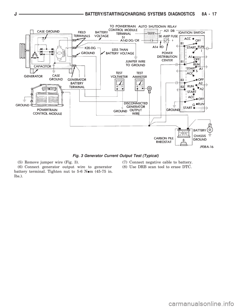
(5) Remove jumper wire (Fig. 3).
(6) Connect generator output wire to generator
battery terminal. Tighten nut to 5-6 NIm (45-75 in.
lbs.).(7) Connect negative cable to battery.
(8) Use DRB scan tool to erase DTC.
Fig. 3 Generator Current Output Test (Typical)
JBATTERY/STARTING/CHARGING SYSTEMS DIAGNOSTICS 8A - 17
Page 291 of 1784
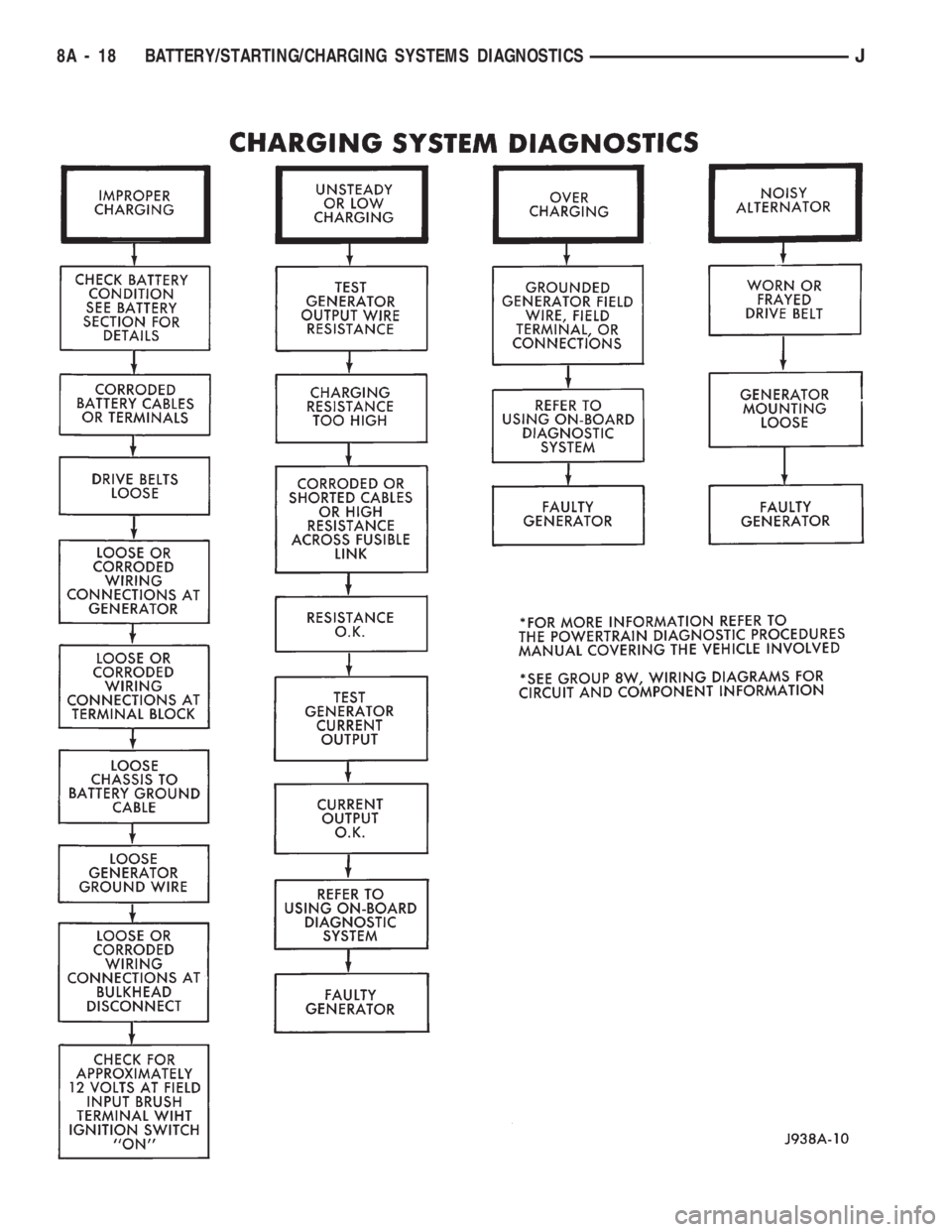
8A - 18 BATTERY/STARTING/CHARGING SYSTEMS DIAGNOSTICSJ
Page 292 of 1784
USING ON-BOARD DIAGNOSTIC SYSTEM
OPERATION OF ON-BOARD DIAGNOSTIC
(OBD) SYSTEM
The Powertrain Control Module (PCM) monitors
critical input and output circuits of the charging sys-
tem making sure they are OK. Some are checked
continuously and some are checked only under cer-
tain conditions.
If OBD system senses that one critical circuit is
bad during the monitoring cycle, it will put a diag-
nostic trouble code into memory. Each input and out-
put circuit monitored by the OBD system has its own
diagnostic trouble code. The diagnostic trouble code
(DTC) will stay in memory as long as the circuit con-
tinues to be bad. If the problem does not happen
again after the fault code is put into memory, the
PCM is programmed to clear the memory after 50 en-
gine starts.
DIAGNOSTIC TROUBLE CODES (DTC)
Diagnostic trouble codes are two-digit numbers
flashed on Malfunction Indicator (Check Engine)
Lamp that identify which circuit is bad. In most
cases they do not identify which component in a cir-
cuit is bad. A trouble code description can be read us-
ing the DRB scan tool. Refer to Group 14 - Fuel
Systems for more information. Therefore, a DTC is
only a symptom, not necessarily the cause for the
problem. In some cases, because of the design of the
driveability test procedure, a DTC can be the reason
for the problem. It is important that the test proce-
dure be followed to understand what caused the DTC
of the on-board diagnostic system to be set.
HOW TO USE MALFUNCTION INDICATOR (CHECK
ENGINE) LAMP FOR DIAGNOSTIC TROUBLE
CODES
To start this function, cycle the ignition switch ON-
OFF-ON-OFF-ON within 5 seconds and any trouble
code stored in the PCM will be displayed. The Mal-
function Indicator (Check Engine) Lamp will display
a DTC by flashing on and off. There is a short pause
between flashes and a longer pause between digits.
All codes displayed are two digit numbers with a 4
second pause between codes.
An example of a code is as follows:
(1) Lamp on for 2 seconds, then turns off.
(2) Lamp flashes 4 times pauses and then flashes 1
time.
(3) Lamp pauses for 4 seconds, flashes 4 times,
pauses and then flashes 7 times.
The 2 codes are 41 and 47. Any number of codes
can be displayed as long as they are in memory. The
lamp will flash until all are displayed (55 = End of
test).
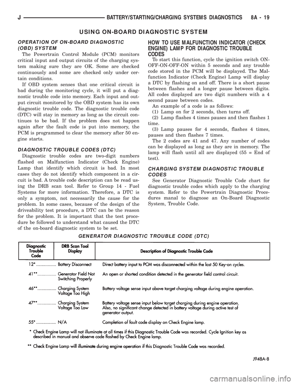
CHARGING SYSTEM DIAGNOSTIC TROUBLE
CODES
See Generator Diagnostic Trouble Code chart for
diagnostic trouble codes which apply to the charging
system. Refer to the Powertrain Diagnostic Proce-
dures manal to diagnose an On-Board Diagnostic
System, Trouble Code.
GENERATOR DIAGNOSTIC TROUBLE CODE (DTC)
JBATTERY/STARTING/CHARGING SYSTEMS DIAGNOSTICS 8A - 19