1994 JEEP CHEROKEE battery
[x] Cancel search: batteryPage 256 of 1784
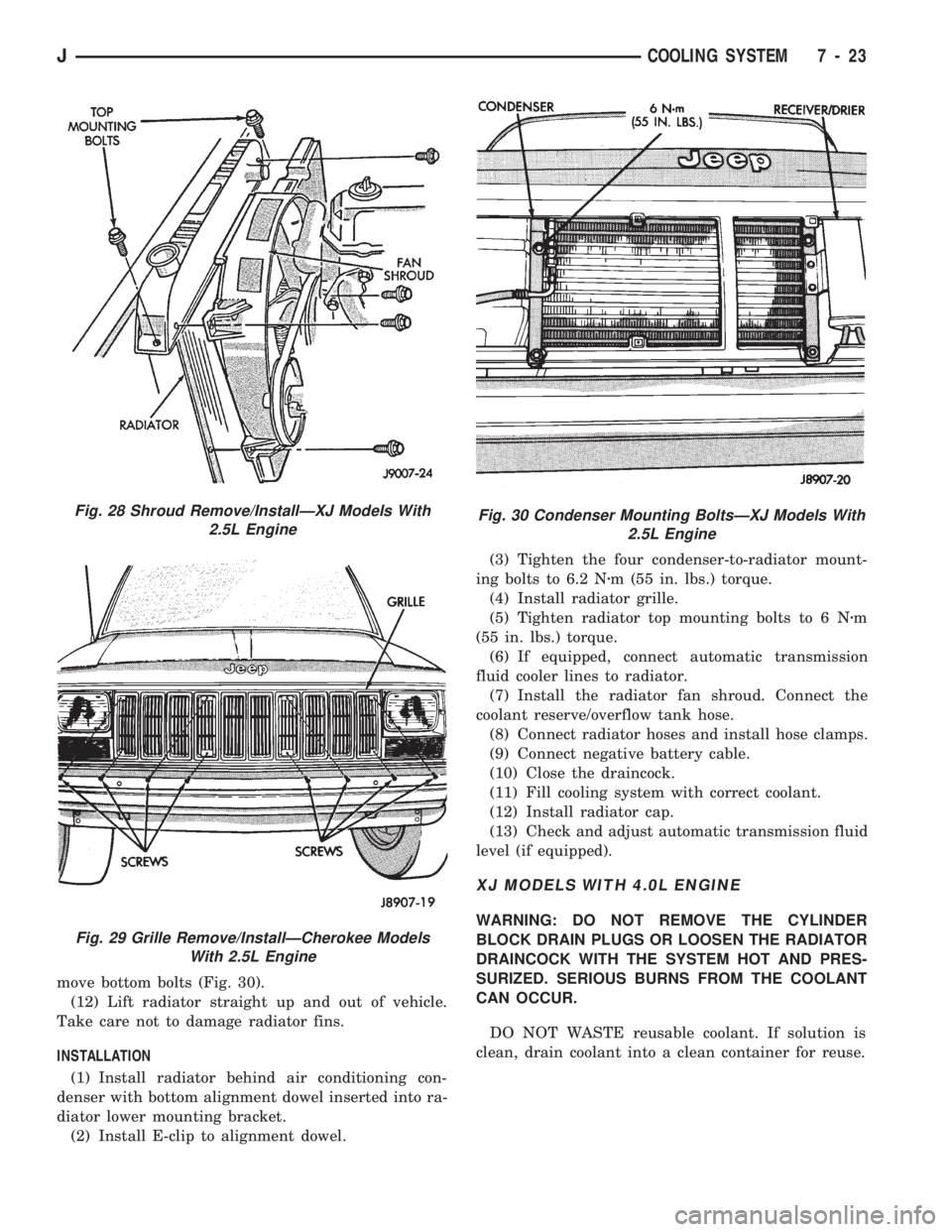
move bottom bolts (Fig. 30).
(12) Lift radiator straight up and out of vehicle.
Take care not to damage radiator fins.
INSTALLATION
(1) Install radiator behind air conditioning con-
denser with bottom alignment dowel inserted into ra-
diator lower mounting bracket.
(2) Install E-clip to alignment dowel.(3) Tighten the four condenser-to-radiator mount-
ing bolts to 6.2 Nzm (55 in. lbs.) torque.
(4) Install radiator grille.
(5) Tighten radiator top mounting bolts to 6 Nzm
(55 in. lbs.) torque.
(6) If equipped, connect automatic transmission
fluid cooler lines to radiator.
(7) Install the radiator fan shroud. Connect the
coolant reserve/overflow tank hose.
(8) Connect radiator hoses and install hose clamps.
(9) Connect negative battery cable.
(10) Close the draincock.
(11) Fill cooling system with correct coolant.
(12) Install radiator cap.
(13) Check and adjust automatic transmission fluid
level (if equipped).
XJ MODELS WITH 4.0L ENGINE
WARNING: DO NOT REMOVE THE CYLINDER
BLOCK DRAIN PLUGS OR LOOSEN THE RADIATOR
DRAINCOCK WITH THE SYSTEM HOT AND PRES-
SURIZED. SERIOUS BURNS FROM THE COOLANT
CAN OCCUR.
DO NOT WASTE reusable coolant. If solution is
clean, drain coolant into a clean container for reuse.
Fig. 28 Shroud Remove/InstallÐXJ Models With
2.5L Engine
Fig. 29 Grille Remove/InstallÐCherokee Models
With 2.5L Engine
Fig. 30 Condenser Mounting BoltsÐXJ Models With
2.5L Engine
JCOOLING SYSTEM 7 - 23
Page 257 of 1784
WARNING: CONSTANT TENSION HOSE CLAMPS
ARE USED ON MOST COOLING SYSTEM HOSES.
WHEN REMOVING OR INSTALLING, USE ONLY
TOOLS DESIGNED FOR SERVICING THIS TYPE OF
CLAMP, SUCH AS SPECIAL CLAMP TOOL (NUM-
BER 6094) (FIG. 26). SNAP-ON CLAMP TOOL (NUM-
BER HPC-20) MAY BE USED FOR LARGER
CLAMPS. ALWAYS WEAR SAFETY GLASSES
WHEN SERVICING CONSTANT TENSION CLAMPS.
CAUTION: A number or letter is stamped into the
tongue of constant tension clamps. If replacement
is necessary, use only an original equipment clamp
with matching number or letter.
REMOVAL
(1) Disconnect negative battery cable at battery.
(2) Observe the previousWARNINGS.
(3) Remove pressure cap.
(4) For access to radiator draincock, remove radia-
tor grille (Fig. 29).
(5) Attach one end of a 24 inch long X 1/4 inch ID
hose to the radiator draincock. Put the other end into
a clean container. Open draincock and drain radia-
tor.
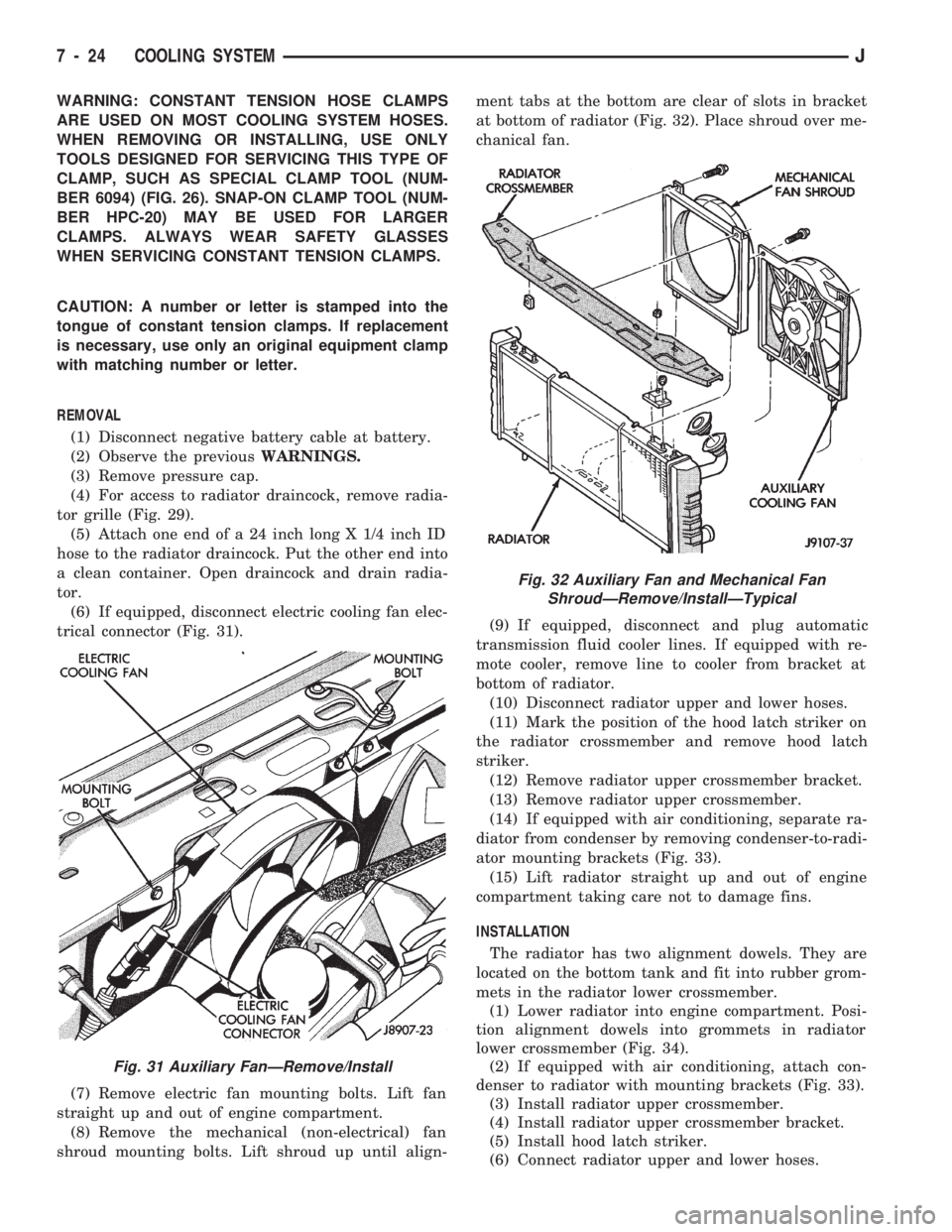
(6) If equipped, disconnect electric cooling fan elec-
trical connector (Fig. 31).
(7) Remove electric fan mounting bolts. Lift fan
straight up and out of engine compartment.
(8) Remove the mechanical (non-electrical) fan
shroud mounting bolts. Lift shroud up until align-ment tabs at the bottom are clear of slots in bracket
at bottom of radiator (Fig. 32). Place shroud over me-
chanical fan.
(9) If equipped, disconnect and plug automatic
transmission fluid cooler lines. If equipped with re-
mote cooler, remove line to cooler from bracket at
bottom of radiator.
(10) Disconnect radiator upper and lower hoses.
(11) Mark the position of the hood latch striker on
the radiator crossmember and remove hood latch
striker.
(12) Remove radiator upper crossmember bracket.
(13) Remove radiator upper crossmember.
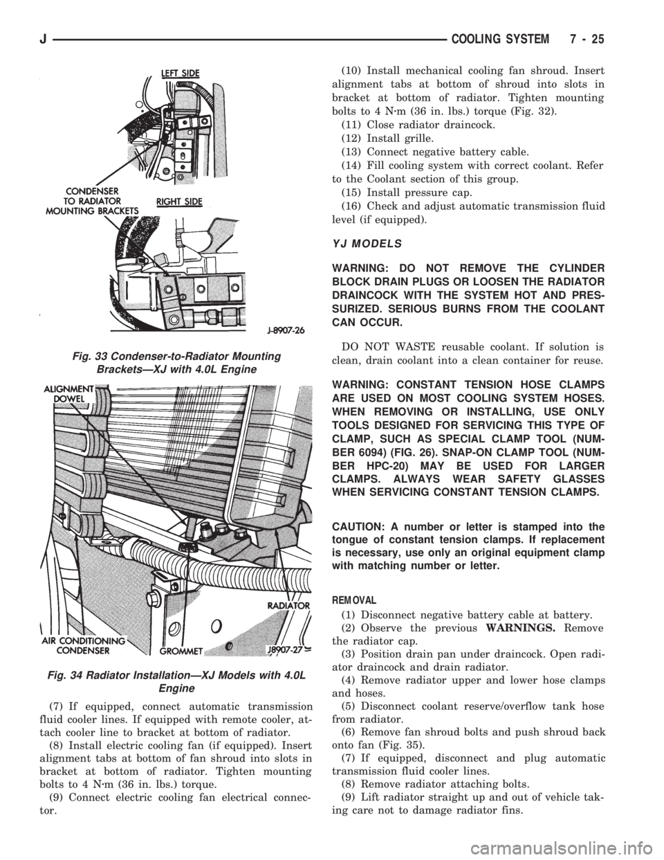
(14) If equipped with air conditioning, separate ra-
diator from condenser by removing condenser-to-radi-
ator mounting brackets (Fig. 33).
(15) Lift radiator straight up and out of engine
compartment taking care not to damage fins.
INSTALLATION
The radiator has two alignment dowels. They are
located on the bottom tank and fit into rubber grom-
mets in the radiator lower crossmember.
(1) Lower radiator into engine compartment. Posi-
tion alignment dowels into grommets in radiator
lower crossmember (Fig. 34).
(2) If equipped with air conditioning, attach con-
denser to radiator with mounting brackets (Fig. 33).
(3) Install radiator upper crossmember.
(4) Install radiator upper crossmember bracket.
(5) Install hood latch striker.
(6) Connect radiator upper and lower hoses.
Fig. 31 Auxiliary FanÐRemove/Install
Fig. 32 Auxiliary Fan and Mechanical Fan
ShroudÐRemove/InstallÐTypical
7 - 24 COOLING SYSTEMJ
Page 258 of 1784
(7) If equipped, connect automatic transmission
fluid cooler lines. If equipped with remote cooler, at-
tach cooler line to bracket at bottom of radiator.
(8) Install electric cooling fan (if equipped). Insert
alignment tabs at bottom of fan shroud into slots in
bracket at bottom of radiator. Tighten mounting
bolts to 4 Nzm (36 in. lbs.) torque.
(9) Connect electric cooling fan electrical connec-
tor.(10) Install mechanical cooling fan shroud. Insert
alignment tabs at bottom of shroud into slots in
bracket at bottom of radiator. Tighten mounting
bolts to 4 Nzm (36 in. lbs.) torque (Fig. 32).
(11) Close radiator draincock.
(12) Install grille.
(13) Connect negative battery cable.
(14) Fill cooling system with correct coolant. Refer
to the Coolant section of this group.
(15) Install pressure cap.
(16) Check and adjust automatic transmission fluid
level (if equipped).
YJ MODELS
WARNING: DO NOT REMOVE THE CYLINDER
BLOCK DRAIN PLUGS OR LOOSEN THE RADIATOR
DRAINCOCK WITH THE SYSTEM HOT AND PRES-
SURIZED. SERIOUS BURNS FROM THE COOLANT
CAN OCCUR.
DO NOT WASTE reusable coolant. If solution is
clean, drain coolant into a clean container for reuse.
WARNING: CONSTANT TENSION HOSE CLAMPS
ARE USED ON MOST COOLING SYSTEM HOSES.
WHEN REMOVING OR INSTALLING, USE ONLY
TOOLS DESIGNED FOR SERVICING THIS TYPE OF
CLAMP, SUCH AS SPECIAL CLAMP TOOL (NUM-
BER 6094) (FIG. 26). SNAP-ON CLAMP TOOL (NUM-
BER HPC-20) MAY BE USED FOR LARGER
CLAMPS. ALWAYS WEAR SAFETY GLASSES
WHEN SERVICING CONSTANT TENSION CLAMPS.
CAUTION: A number or letter is stamped into the
tongue of constant tension clamps. If replacement
is necessary, use only an original equipment clamp
with matching number or letter.
REMOVAL
(1) Disconnect negative battery cable at battery.
(2) Observe the previousWARNINGS.Remove
the radiator cap.
(3) Position drain pan under draincock. Open radi-
ator draincock and drain radiator.
(4) Remove radiator upper and lower hose clamps
and hoses.
(5) Disconnect coolant reserve/overflow tank hose
from radiator.
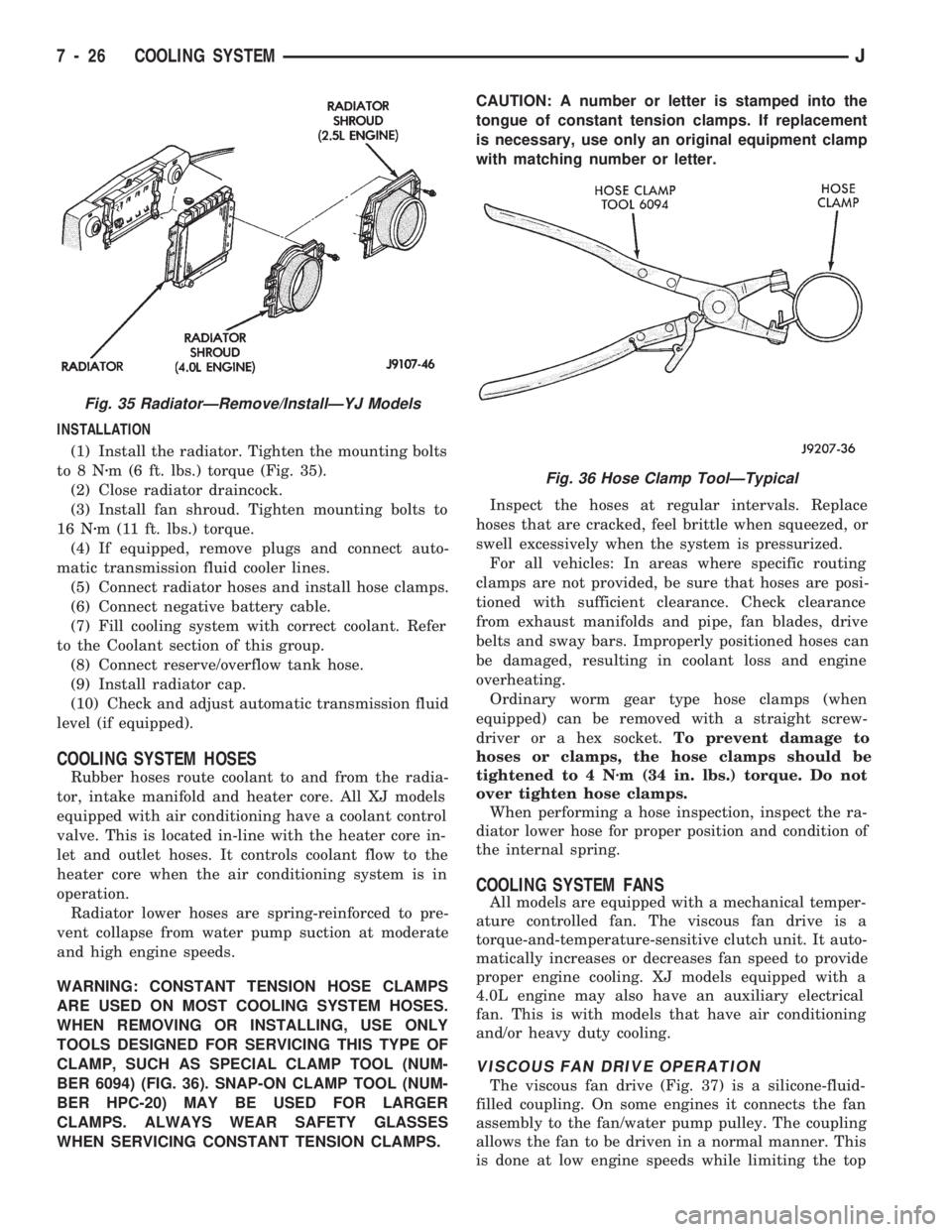
(6) Remove fan shroud bolts and push shroud back
onto fan (Fig. 35).
(7) If equipped, disconnect and plug automatic
transmission fluid cooler lines.
(8) Remove radiator attaching bolts.
(9) Lift radiator straight up and out of vehicle tak-
ing care not to damage radiator fins.
Fig. 33 Condenser-to-Radiator Mounting
BracketsÐXJ with 4.0L Engine
Fig. 34 Radiator InstallationÐXJ Models with 4.0L
Engine
JCOOLING SYSTEM 7 - 25
Page 259 of 1784
INSTALLATION
(1) Install the radiator. Tighten the mounting bolts
to8Nzm (6 ft. lbs.) torque (Fig. 35).
(2) Close radiator draincock.
(3) Install fan shroud. Tighten mounting bolts to
16 Nzm (11 ft. lbs.) torque.
(4) If equipped, remove plugs and connect auto-
matic transmission fluid cooler lines.
(5) Connect radiator hoses and install hose clamps.
(6) Connect negative battery cable.
(7) Fill cooling system with correct coolant. Refer
to the Coolant section of this group.
(8) Connect reserve/overflow tank hose.
(9) Install radiator cap.
(10) Check and adjust automatic transmission fluid
level (if equipped).
COOLING SYSTEM HOSES
Rubber hoses route coolant to and from the radia-
tor, intake manifold and heater core. All XJ models
equipped with air conditioning have a coolant control
valve. This is located in-line with the heater core in-
let and outlet hoses. It controls coolant flow to the
heater core when the air conditioning system is in
operation.
Radiator lower hoses are spring-reinforced to pre-
vent collapse from water pump suction at moderate
and high engine speeds.
WARNING: CONSTANT TENSION HOSE CLAMPS
ARE USED ON MOST COOLING SYSTEM HOSES.
WHEN REMOVING OR INSTALLING, USE ONLY
TOOLS DESIGNED FOR SERVICING THIS TYPE OF
CLAMP, SUCH AS SPECIAL CLAMP TOOL (NUM-
BER 6094) (FIG. 36). SNAP-ON CLAMP TOOL (NUM-
BER HPC-20) MAY BE USED FOR LARGER
CLAMPS. ALWAYS WEAR SAFETY GLASSES
WHEN SERVICING CONSTANT TENSION CLAMPS.CAUTION: A number or letter is stamped into the
tongue of constant tension clamps. If replacement
is necessary, use only an original equipment clamp
with matching number or letter.
Inspect the hoses at regular intervals. Replace
hoses that are cracked, feel brittle when squeezed, or
swell excessively when the system is pressurized.
For all vehicles: In areas where specific routing
clamps are not provided, be sure that hoses are posi-
tioned with sufficient clearance. Check clearance
from exhaust manifolds and pipe, fan blades, drive
belts and sway bars. Improperly positioned hoses can
be damaged, resulting in coolant loss and engine
overheating.
Ordinary worm gear type hose clamps (when
equipped) can be removed with a straight screw-
driver or a hex socket.To prevent damage to
hoses or clamps, the hose clamps should be
tightened to 4 Nzm (34 in. lbs.) torque. Do not
over tighten hose clamps.
When performing a hose inspection, inspect the ra-
diator lower hose for proper position and condition of
the internal spring.
COOLING SYSTEM FANS
All models are equipped with a mechanical temper-
ature controlled fan. The viscous fan drive is a
torque-and-temperature-sensitive clutch unit. It auto-
matically increases or decreases fan speed to provide
proper engine cooling. XJ models equipped with a
4.0L engine may also have an auxiliary electrical
fan. This is with models that have air conditioning
and/or heavy duty cooling.
VISCOUS FAN DRIVE OPERATION
The viscous fan drive (Fig. 37) is a silicone-fluid-
filled coupling. On some engines it connects the fan
assembly to the fan/water pump pulley. The coupling
allows the fan to be driven in a normal manner. This
is done at low engine speeds while limiting the top
Fig. 35 RadiatorÐRemove/InstallÐYJ Models
Fig. 36 Hose Clamp ToolÐTypical
7 - 26 COOLING SYSTEMJ
Page 261 of 1784
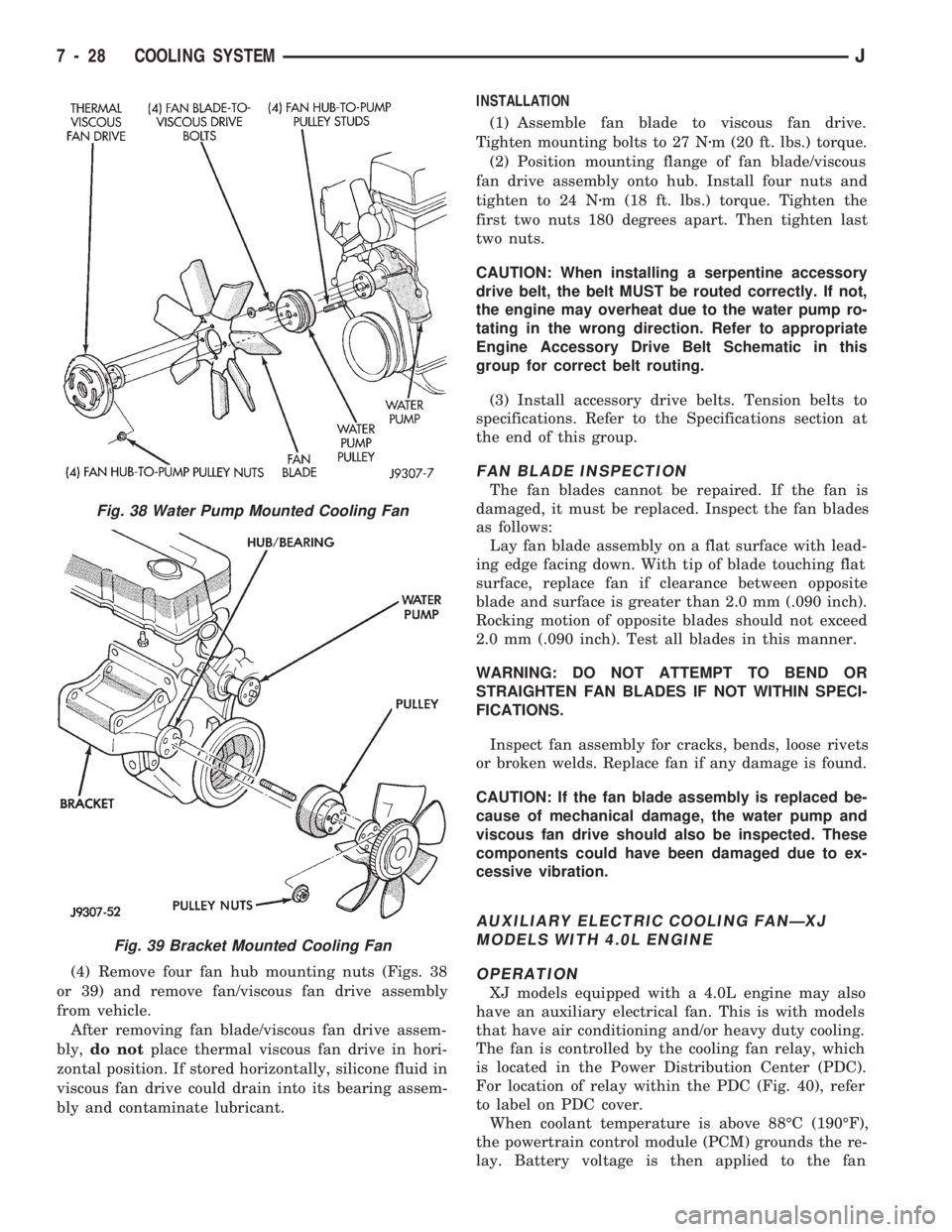
(4) Remove four fan hub mounting nuts (Figs. 38
or 39) and remove fan/viscous fan drive assembly
from vehicle.
After removing fan blade/viscous fan drive assem-
bly,do notplace thermal viscous fan drive in hori-
zontal position. If stored horizontally, silicone fluid in
viscous fan drive could drain into its bearing assem-
bly and contaminate lubricant.INSTALLATION
(1) Assemble fan blade to viscous fan drive.
Tighten mounting bolts to 27 Nzm (20 ft. lbs.) torque.
(2) Position mounting flange of fan blade/viscous
fan drive assembly onto hub. Install four nuts and
tighten to 24 Nzm (18 ft. lbs.) torque. Tighten the
first two nuts 180 degrees apart. Then tighten last
two nuts.
CAUTION: When installing a serpentine accessory
drive belt, the belt MUST be routed correctly. If not,
the engine may overheat due to the water pump ro-
tating in the wrong direction. Refer to appropriate
Engine Accessory Drive Belt Schematic in this
group for correct belt routing.
(3) Install accessory drive belts. Tension belts to
specifications. Refer to the Specifications section at
the end of this group.
FAN BLADE INSPECTION
The fan blades cannot be repaired. If the fan is
damaged, it must be replaced. Inspect the fan blades
as follows:
Lay fan blade assembly on a flat surface with lead-
ing edge facing down. With tip of blade touching flat
surface, replace fan if clearance between opposite
blade and surface is greater than 2.0 mm (.090 inch).
Rocking motion of opposite blades should not exceed
2.0 mm (.090 inch). Test all blades in this manner.
WARNING: DO NOT ATTEMPT TO BEND OR
STRAIGHTEN FAN BLADES IF NOT WITHIN SPECI-
FICATIONS.
Inspect fan assembly for cracks, bends, loose rivets
or broken welds. Replace fan if any damage is found.
CAUTION: If the fan blade assembly is replaced be-
cause of mechanical damage, the water pump and
viscous fan drive should also be inspected. These
components could have been damaged due to ex-
cessive vibration.
AUXILIARY ELECTRIC COOLING FANÐXJ
MODELS WITH 4.0L ENGINE
OPERATION
XJ models equipped with a 4.0L engine may also
have an auxiliary electrical fan. This is with models
that have air conditioning and/or heavy duty cooling.
The fan is controlled by the cooling fan relay, which
is located in the Power Distribution Center (PDC).
For location of relay within the PDC (Fig. 40), refer
to label on PDC cover.
When coolant temperature is above 88ÉC (190ÉF),
the powertrain control module (PCM) grounds the re-
lay. Battery voltage is then applied to the fan
Fig. 38 Water Pump Mounted Cooling Fan
Fig. 39 Bracket Mounted Cooling Fan
7 - 28 COOLING SYSTEMJ
Page 274 of 1784
ELECTRICAL
GROUP INDEX
Group Group
AUDIO SYSTEMS....................... 8F
BATTERY/STARTER/GENERATOR SERVICE . . 8B
BATTERY/STARTING/CHARGING SYSTEMS
DIAGNOSTICS........................ 8A
CHIME/WARNING BUZZER SYSTEM....... 8U
HORNS............................... 8G
IGNITION SYSTEMS.................... 8D
INSTRUMENT PANEL AND GAUGES........ 8E
LAMPS............................... 8L
OVERHEAD CONSOLE................... 8CPOWER LOCKS........................ 8P
POWER MIRRORS...................... 8T
POWER SEAT.......................... 8R
POWER WINDOWS..................... 8S
REAR WINDOW DEFOGGER.............. 8N
TURN SIGNALS AND HAZARD WARNING
FLASHERS........................... 8J
VEHICLE SPEED CONTROL SYSTEM....... 8H
WINDSHIELD WIPERS AND WASHERS..... 8K
WIRING DIAGRAMS.................... 8W
BATTERY/STARTING/CHARGING SYSTEMS DIAGNOSTICS
CONTENTS
page page
BATTERY TEST PROCEDURES............. 2
ENGINE STARTER MOTOR TEST
PROCEDURES ON VEHICLE.............. 9GENERATOR TEST PROCEDURES ON
VEHICLE............................. 14
IGNITION OFF DRAW (IOD) DIAGNOSIS...... 8
USING ON-BOARD DIAGNOSTIC SYSTEM.... 19
GENERAL INFORMATION
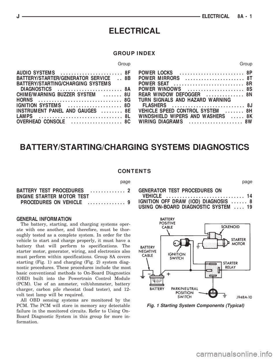
The battery, starting, and charging systems oper-
ate with one another, and therefore, must be thor-
oughly tested as a complete system. In order for the
vehicle to start and charge properly, it must have a
battery that will perform to specifications. The
starter motor, generator, wiring, and electronics also
must perform within specifications. Group 8A covers
starting (Fig. 1) and charging (Fig. 2) system diag-
nostic procedures. These procedures include the most
basic conventional methods to On-Board Diagnostics
(OBD) built into the Powertrain Control Module
(PCM). Use of an ammeter, volt/ohmmeter, battery
charger, carbon pile rheostat (load tester), and 12-
volt test lamp will be required.
All OBD sensing systems are monitored by the
PCM. The PCM will store in memory any detectable
failure in the monitored circuits. Refer to Using On-
Board Diagnostic System in this group for more in-
formation.
Fig. 1 Starting System Components (Typical)
JELECTRICAL 8A - 1
Page 275 of 1784
BATTERY TEST PROCEDURES
INDEX
page page
Battery Charging.......................... 5
Battery Diagnostics Chart................... 7
Battery Load Test......................... 4
Battery Open Circuit Voltage Test............. 3Battery Testing General Information........... 3
General Information........................ 2
Hydrometer Test.......................... 3
Specifications............................ 8
GENERAL INFORMATION
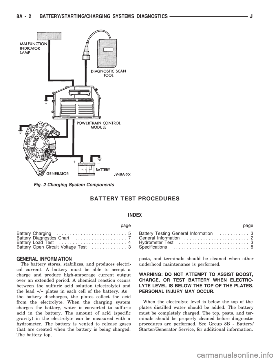
The battery stores, stabilizes, and produces electri-
cal current. A battery must be able to accept a
charge and produce high-amperage current output
over an extended period. A chemical reaction occurs
between the sulfuric acid solution (electrolyte) and
the lead +/þ plates in each cell of the battery. As
the battery discharges, the plates collect the acid
from the electrolyte. When the charging system
charges the battery, water is converted to sulfuric
acid in the battery. The amount of acid (specific
gravity) in the electrolyte can be measured with a
hydrometer. The battery is vented to release gases
that are created when the battery is being charged.
The battery top,posts, and terminals should be cleaned when other
underhood maintenance is performed.
WARNING: DO NOT ATTEMPT TO ASSIST BOOST,
CHARGE, OR TEST BATTERY WHEN ELECTRO-
LYTE LEVEL IS BELOW THE TOP OF THE PLATES.
PERSONAL INJURY MAY OCCUR.
When the electrolyte level is below the top of the
plates distilled water should be added. The battery
must be completely charged. The top, posts, and ter-
minals should be properly cleaned before diagnostic
procedures are performed. See Group 8B - Battery/
Starter/Generator Service, for additional information.
Fig. 2 Charging System Components
8A - 2 BATTERY/STARTING/CHARGING SYSTEMS DIAGNOSTICSJ
Page 276 of 1784
BATTERY TESTING GENERAL INFORMATION
Before testing a battery, clean the top of the
battery case, posts and cable terminals.
Specific gravity is a ratio of the density of the elec-
trolyte and the density of pure water. The electrolyte
is composed of sulfuric acid and water. Acid makes
up approximately 35% of the electrolyte by weight,
or 24% by volume.
The condition of a battery may be determined from
the results of 2 tests:
²hydrometer test
²ability to supply current (battery load test)
Perform the hydrometer test first. If the specific
gravity is less than 1.235, (with battery at room tem-
perature) the battery must be charged before pro-
ceeding with further testing. A battery that will not
accept a charge is defective and further testing is not
necessary.
Completely discharged batteries may take sev-
eral hours to accept a charge. See Charging
Completely Discharged Battery.
A battery that has been fully charged but does not
pass the battery load test is defective.
A battery is fully charged when:
²all cells are gassing freely during charging
²3 corrected specific gravity tests, taken at 1-hour
intervals, indicate no increase in specific gravity.
ABNORMAL BATTERY DISCHARGING
(1) Corroded battery posts and terminals.
(2) Loose or worn generator drive belt.
(3) Electrical loads that exceed the output of the
charging system due to equipment or accessories in-
stalled after delivery.
(4) Slow driving speeds (heavy traffic conditions)
or prolonged idling with high-amperage draw sys-
tems in use.
(5) Defective circuit or component causing excess
IOD. Refer to Ignition Off Draw Diagnosis in this
group.
(6) Defective charging system.
(7) Defective battery.
HYDROMETER TEST
Before performing a hydrometer test, remove
battery caps and check electrolyte level. Add
distilled water as required.
Before testing, visually inspect battery for any
damage (cracked case or cover, loose post, etc.) that
would cause the battery to be defective. To use the
hydrometer correctly, hold it with the top surface of
the electrolyte at eye level. Refer to manufacturers
instructions for correct use of hydrometer.
Remove only enough electrolyte from the battery to
keep the float off the bottom of the hydrometer bar-
rel with pressure on the bulb released. Exercise care
when inserting the tip of the hydrometer into a cellto avoid damage to the separators. Damaged separa-
tors can cause premature battery failure.
Hydrometer floats are generally calibrated to indi-
cate the specific gravity correctly only at one fixed
temperature, 80ÉF (26.6ÉC). When testing the specific
gravity at any other temperature, a correction factor
is required.
The correction factor is approximately a specific
gravity value of 0.004, referred to as 4 points of spe-
cific gravity. For each 10ÉF above 80ÉF (5.5ÉC above
26.6ÉC), add 4 points. For each 10ÉF below 80ÉF
(5.5ÉC below 26.6ÉC), subtract 4 points. Always cor-
rect the specific gravity for temperature variation.
Test the specific gravity of the electrolyte in each
battery cell.
Example: A battery is tested at 10ÉF (-12.2ÉC) and
has a specific gravity of 1.240. Determine the actual
specific gravity as follows:
²Determine the number of degrees above or below
80ÉF:
80ÉF - 10ÉF = 70ÉF
²Divide the result above by 10:
70ÉF/10 = 7
²Multiply the result from the previous step by the
temperature correction factor (0.004):
7 x 0.004 = 0.028
²The temperature at testing was below 80ÉF, there-
fore the temperature correction is subtracted:
1.240 - 0.028 = 1.212
²The corrected specific gravity is 1.212.
The fully charged battery should have a tempera-
ture corrected specific gravity of 1.260 to 1.290.
If the specific gravity of all cells is above 1.235,
and cell variation is more than 50 points (0.050), it is
an indication that the battery is unserviceable.
If the specific gravity of one or more cells is less
than 1.235, charge the battery at a rate of approxi-
mately 5 amperes. Continue charging until 3 consec-
utive specific gravity tests, taken at 1 hour intervals,
are constant.
If the cell specific gravity variation is more than 50
points (0.050) after the charge period, replace the
battery.
When the specific gravity of all cells is above 1.235
and variation between cells is less than 50 points
(0.050), the battery may be tested under heavy load.
BATTERY OPEN CIRCUIT VOLTAGE TEST
A battery voltage (no load) test will show state of
charge of a battery that will pass the Battery Load
Test described in this section.Before proceeding
with this test or Battery Load Test, completely
charge battery as described in Battery Charging
in this section.
If a battery has a no load voltage reading of 12.4
volts or greater and will not endure a load test, it is
defective and should be replaced. Refer to Group 8B -
JBATTERY/STARTING/CHARGING SYSTEMS DIAGNOSTICS 8A - 3