1993 FORD MONDEO transmission oil
[x] Cancel search: transmission oilPage 75 of 279
gear linkage heat shield. Reconnect the
gearchange linkage and transmission support
rods to the transmission, adjusting the linkage
using the marks made on removal (see
Chapter 7, Part A, for details).
56Re-install the remaining components and
fasteners in the reverse order of removal.
57Add coolant, engine oil and transmission
fluids as needed (see Chapter 1).
58Run the engine, and check for proper
operation and the absence of leaks. Shut off
the engine, and recheck the fluid levels.
59Remember that, since the front suspension
subframe and steering gear have been
disturbed, the wheel alignment and steering
angles must be checked fully and carefully as
soon as possible, with any necessary
adjustments being made. This operation is best
carried out by an experienced mechanic, using
proper checking equipment; the vehicle should
therefore be taken to a Ford dealer or similarly-
qualified person for attention.
1It is much easier to dismantle and work on
the engine if it is mounted on a portable engine
stand. These stands can often be hired from a
tool hire shop. Before the engine is mounted
on a stand, the flywheel/driveplate should be
removed (Part A of this Chapter, Section 21)
so that the stand bolts can be tightened into
the end of the cylinder block/crankcase.
2If a stand is not available, it is possible to
dismantle the engine with it mounted on
blocks, on a sturdy workbench or on the floor.
Be extra-careful not to tip or drop the engine
when working without a stand.
3If you are going to obtain a reconditioned
engine, all external components must be
removed first, to be transferred to the
replacement engine (just as they will if you are
doing a complete engine overhaul yourself).
Note:When removing the external
components from the engine, pay close
attention to details that may be helpful or
important during refitting. Note the fitted
position of gaskets, seals, spacers, pins,
washers, bolts and other small items.These
external components include the following:
(a) Alternator and brackets (Chapter 5).
(b) HT leads and spark plugs (Chapter 1).
(c) Thermostat and housing (Chapter 3).
(d) Dipstick tube.
(e) Fuel injection system components
(Chapter 4).
(f) All electrical switches and sensors - refer
to the appropriate Chapter.
(g) Inlet and exhaust manifolds (Part A of this
Chapter).
(h) Oil filter (Chapter 1).
(i) Engine/transmission mounting brackets
(Part A of this Chapter, Section 22).
(j) Flywheel/driveplate (Part A of this
Chapter, Section 21).
4If you are obtaining a “short” engine (whichconsists of the engine cylinder
block/crankcase, crankshaft, pistons and
connecting rods all assembled), then the
cylinder head, sump, oil pump, and timing belt
will have to be removed also.
5If you are planning a complete overhaul, the
engine can be dismantled and the internal
components removed in the following order.
(a) Inlet and exhaust manifolds (Part A of this
Chapter).
(b) Timing belt, toothed pulleys and
tensioner, and timing belt inner cover
(Part A of this Chapter).
(c) Cylinder head (Part A of this Chapter,
Section 14).
(d) Flywheel/driveplate (Part A of this
Chapter, Section 21).
(e) Sump (Part A of this Chapter, Section 15).
(f) Oil pump (Part A of this Chapter, Sec-
tion 16).
(g) Piston/connecting rod assemblies
(Section 9).
(h) Crankshaft (Section 10).
6Before beginning the dismantling andoverhaul procedures, make sure that you have
all of the correct tools necessary. Refer to the
introductory pages at the beginning of this
manual for further information.
Note:New and reconditioned cylinder heads
are available from the manufacturers, and
from engine overhaul specialists. Due to the
fact that some specialist tools are required for
the dismantling and inspection procedures,
and new components may not be readily
available (refer to Section 1 of this Part), it may
be more practical and economical for the
home mechanic to purchase a reconditioned
head, rather than to dismantle, inspect and
recondition the original head.
1Remove the camshafts and hydraulic
tappets (Part A of this Chapter, Section 13),
being careful to store the hydraulic tappets as
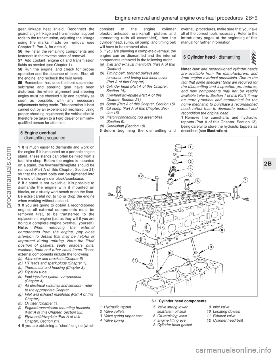
described (see illustration).
6 Cylinder head - dismantling
5 Engine overhaul-
dismantling sequence
Engine removal and general engine overhaul procedures 2B•9
2B
6.1 Cylinder head components
1 Hydraulic tappet
2 Valve collets
3 Valve spring upper seat
4 Valve spring5 Valve spring lower
seat/stem oil seal
6 Oil-retaining valve
7 Engine lifting eye
8 Cylinder head gasket9 Inlet valve
10 Locating dowels
11 Exhaust valve
12 Cylinder head bolt
procarmanuals.com
Page 78 of 279
grinding or head resurfacing. Use
compressed air, if available, to blow out all the
oil holes and passages.
2Beginning at one end of the head, lubricate
and install the first valve. Apply molybdenum
disulphide-based grease or clean engine oil to
the valve stem, and refit the valve. Where the
original valves are being re-used, ensure that
each is refitted in its original guide. If new
valves are being fitted, insert them into the
locations to which they have been ground.
3Fit the plastic protector supplied with new
valve spring lower seat/stem oil seals to the
end of the valve stem, then put the new seal
squarely on top of the guide, and leave it
there; the action of refitting the valve spring
presses the lower seat/stem oil seal into place
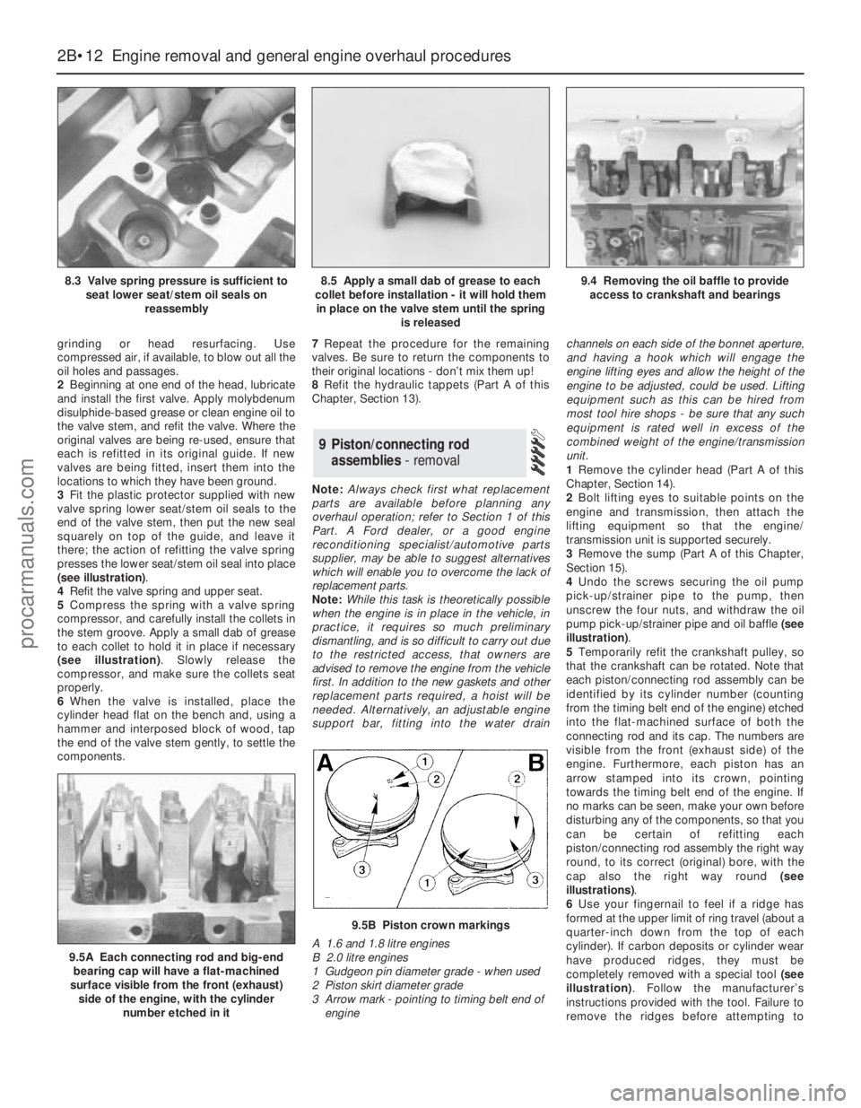
(see illustration).
4Refit the valve spring and upper seat.
5Compress the spring with a valve spring
compressor, and carefully install the collets in
the stem groove. Apply a small dab of grease
to each collet to hold it in place if necessary
(see illustration). Slowly release the
compressor, and make sure the collets seat
properly.
6When the valve is installed, place the
cylinder head flat on the bench and, using a
hammer and interposed block of wood, tap
the end of the valve stem gently, to settle the
components.7Repeat the procedure for the remaining
valves. Be sure to return the components to
their original locations - don’t mix them up!
8Refit the hydraulic tappets (Part A of this
Chapter, Section 13).
Note:Always check first what replacement
parts are available before planning any
overhaul operation; refer to Section 1 of this
Part. A Ford dealer, or a good engine
reconditioning specialist/automotive parts
supplier, may be able to suggest alternatives
which will enable you to overcome the lack of
replacement parts.
Note:While this task is theoretically possible
when the engine is in place in the vehicle, in
practice, it requires so much preliminary
dismantling, and is so difficult to carry out due
to the restricted access, that owners are
advised to remove the engine from the vehicle
first. In addition to the new gaskets and other
replacement parts required, a hoist will be
needed. Alternatively, an adjustable engine
support bar, fitting into the water drainchannels on each side of the bonnet aperture,
and having a hook which will engage the
engine lifting eyes and allow the height of the
engine to be adjusted, could be used. Lifting
equipment such as this can be hired from
most tool hire shops - be sure that any such
equipment is rated well in excess of the
combined weight of the engine/transmission
unit.
1Remove the cylinder head (Part A of this
Chapter, Section 14).
2Bolt lifting eyes to suitable points on the
engine and transmission, then attach the
lifting equipment so that the engine/
transmission unit is supported securely.
3Remove the sump (Part A of this Chapter,
Section 15).
4Undo the screws securing the oil pump
pick-up/strainer pipe to the pump, then
unscrew the four nuts, and withdraw the oil
pump pick-up/strainer pipe and oil baffle (see
illustration).
5Temporarily refit the crankshaft pulley, so
that the crankshaft can be rotated. Note that
each piston/connecting rod assembly can be
identified by its cylinder number (counting
from the timing belt end of the engine) etched
into the flat-machined surface of both the
connecting rod and its cap. The numbers are
visible from the front (exhaust side) of the
engine. Furthermore, each piston has an
arrow stamped into its crown, pointing
towards the timing belt end of the engine. If
no marks can be seen, make your own before
disturbing any of the components, so that you
can be certain of refitting each
piston/connecting rod assembly the right way
round, to its correct (original) bore, with the
cap also the right way round (see
illustrations).
6Use your fingernail to feel if a ridge has
formed at the upper limit of ring travel (about a
quarter-inch down from the top of each
cylinder). If carbon deposits or cylinder wear
have produced ridges, they must be
completely removed with a special tool (see
illustration). Follow the manufacturer’s
instructions provided with the tool. Failure to
remove the ridges before attempting to
9 Piston/connecting rod
assemblies- removal
2B•12 Engine removal and general engine overhaul procedures
8.3 Valve spring pressure is sufficient to
seat lower seat/stem oil seals on
reassembly8.5 Apply a small dab of grease to each
collet before installation - it will hold them
in place on the valve stem until the spring
is released9.4 Removing the oil baffle to provide
access to crankshaft and bearings
9.5A Each connecting rod and big-end
bearing cap will have a flat-machined
surface visible from the front (exhaust)
side of the engine, with the cylinder
number etched in it
9.5B Piston crown markings
A 1.6 and 1.8 litre engines
B 2.0 litre engines
1 Gudgeon pin diameter grade - when used
2 Piston skirt diameter grade
3 Arrow mark - pointing to timing belt end of
engine
procarmanuals.com
Page 79 of 279
remove the piston/connecting rod assemblies
may result in piston ring breakage.
7Slacken each of the big-end bearing cap
bolts half a turn at a time, until they can be
removed by hand. Remove the No 1 cap and
bearing shell. Don’t drop the shell out of the
cap.
8Remove the upper bearing shell, and push
the connecting rod/piston assembly out
through the top of the engine. Use a wooden
hammer handle to push on the connecting
rod’s bearing recess. If resistance is felt,
double-check that all of the ridge was
removed from the cylinder.
9Repeat the procedure for the remaining
cylinders.
10After removal, reassemble the big-end
bearing caps and shells on their respective
connecting rods, and refit the bolts finger-
tight. Leaving the old shells in place until
reassembly will help prevent the bearing
recesses from being accidentally nicked or
gouged. New shells should be used on
reassembly.
11Don’t attempt to separate the pistons
from the connecting rods - see Section 12.
Note:The crankshaft can be removed only
after the engine/transmission has been
removed from the vehicle. It is assumed that
the transmission and flywheel/driveplate,
timing belt, cylinder head, sump, oil pump
pick-up/strainer pipe and oil baffle, oil pump,
and piston/connecting rod assemblies, have
already been removed. The crankshaft left-
hand oil seal carrier must be unbolted from
the cylinder block/crankcase before
proceeding with crankshaft removal.
1Before the crankshaft is removed, check
the endfloat. Mount a DTI (Dial Test Indicator,
or dial gauge) with the stem in line with the
crankshaft and just touching the crankshaft
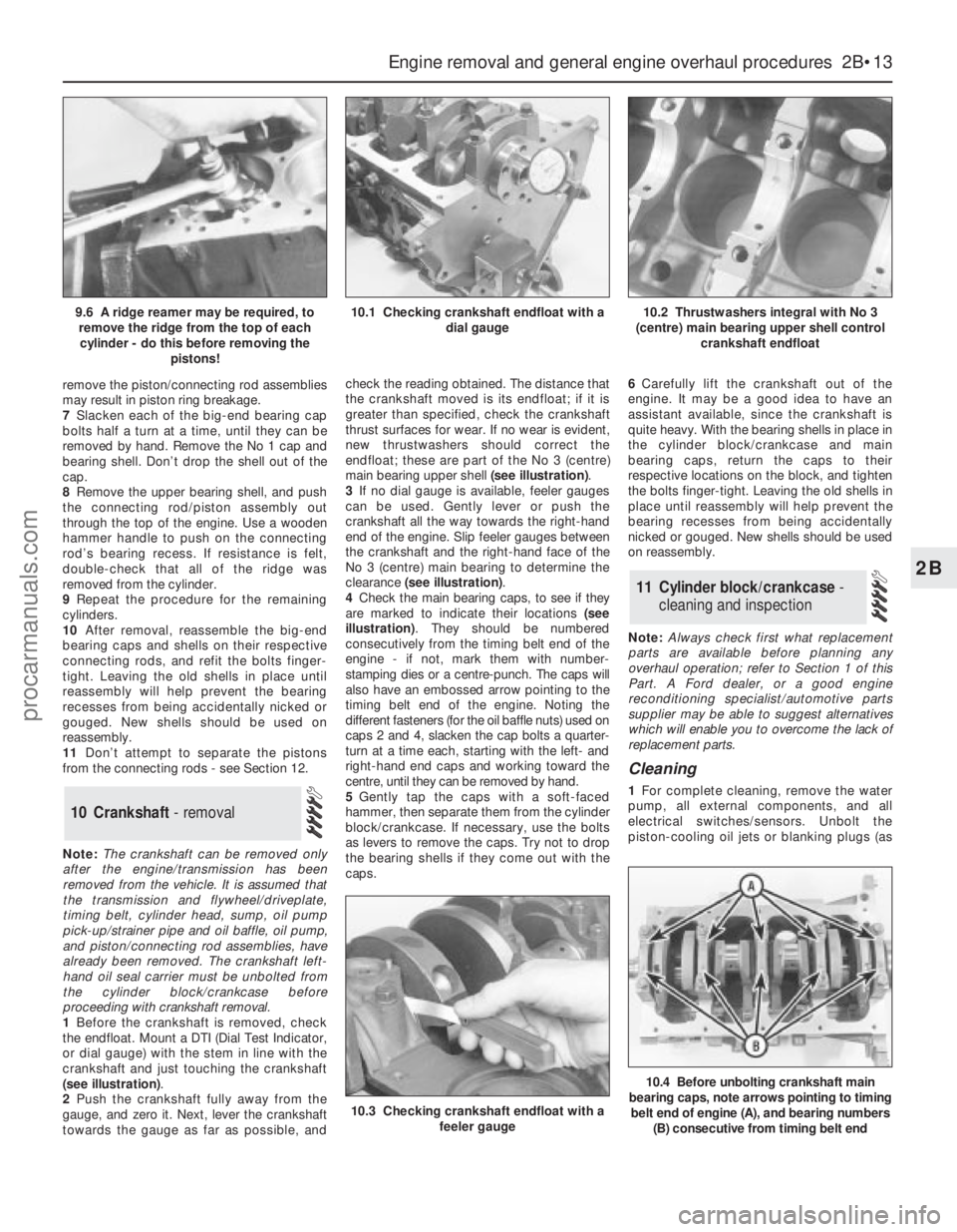
(see illustration).
2Push the crankshaft fully away from the
gauge, and zero it. Next, lever the crankshaft
towards the gauge as far as possible, andcheck the reading obtained. The distance that
the crankshaft moved is its endfloat; if it is
greater than specified, check the crankshaft
thrust surfaces for wear. If no wear is evident,
new thrustwashers should correct the
endfloat; these are part of the No 3 (centre)
main bearing upper shell (see illustration).
3If no dial gauge is available, feeler gauges
can be used. Gently lever or push the
crankshaft all the way towards the right-hand
end of the engine. Slip feeler gauges between
the crankshaft and the right-hand face of the
No 3 (centre) main bearing to determine the
clearance (see illustration).
4Check the main bearing caps, to see if they
are marked to indicate their locations (see
illustration). They should be numbered
consecutively from the timing belt end of the
engine - if not, mark them with number-
stamping dies or a centre-punch. The caps will
also have an embossed arrow pointing to the
timing belt end of the engine. Noting the
different fasteners (for the oil baffle nuts) used on
caps 2 and 4, slacken the cap bolts a quarter-
turn at a time each, starting with the left- and
right-hand end caps and working toward the
centre, until they can be removed by hand.
5Gently tap the caps with a soft-faced
hammer, then separate them from the cylinder
block/crankcase. If necessary, use the bolts
as levers to remove the caps. Try not to drop
the bearing shells if they come out with the
caps.6Carefully lift the crankshaft out of the
engine. It may be a good idea to have an
assistant available, since the crankshaft is
quite heavy. With the bearing shells in place in
the cylinder block/crankcase and main
bearing caps, return the caps to their
respective locations on the block, and tighten
the bolts finger-tight. Leaving the old shells in
place until reassembly will help prevent the
bearing recesses from being accidentally
nicked or gouged. New shells should be used
on reassembly.
Note:Always check first what replacement
parts are available before planning any
overhaul operation; refer to Section 1 of this
Part. A Ford dealer, or a good engine
reconditioning specialist/automotive parts
supplier may be able to suggest alternatives
which will enable you to overcome the lack of
replacement parts.
Cleaning
1For complete cleaning, remove the water
pump, all external components, and all
electrical switches/sensors. Unbolt the
piston-cooling oil jets or blanking plugs (as
11 Cylinder block/crankcase -
cleaning and inspection
10 Crankshaft - removal
Engine removal and general engine overhaul procedures 2B•13
2B
10.3 Checking crankshaft endfloat with a
feeler gauge
10.4 Before unbolting crankshaft main
bearing caps, note arrows pointing to timing
belt end of engine (A), and bearing numbers
(B) consecutive from timing belt end
9.6 A ridge reamer may be required, to
remove the ridge from the top of each
cylinder - do this before removing the
pistons!10.1 Checking crankshaft endfloat with a
dial gauge10.2 Thrustwashers integral with No 3
(centre) main bearing upper shell control
crankshaft endfloat
procarmanuals.com
Page 90 of 279
Torque wrench settingsNm lbf ft
Radiator mounting bracket-to-subframe bolts . . . . . . . . . . . . . . . . . . . . 23 17
Fluid cooler pipe unions - automatic transmission . . . . . . . . . . . . . . . . . 23 17
Thermostat housing-to-cylinder head bolts . . . . . . . . . . . . . . . . . . . . . . 20 15
Water outlet-to-thermostat housing bolts . . . . . . . . . . . . . . . . . . . . . . . 8 to 11 6 to 8
Coolant temperature sensor . . . . . . . . . . . . . . . . . . . . . . . . . . . . . . . . . . 23 17
Coolant temperature gauge sender . . . . . . . . . . . . . . . . . . . . . . . . . . . . 8 6
Water pump bolts . . . . . . . . . . . . . . . . . . . . . . . . . . . . . . . . . . . . . . . . . . 18 13
Water pump pulley bolts . . . . . . . . . . . . . . . . . . . . . . . . . . . . . . . . . . . . . See Chapter 2A
Air conditioning compressor mounting bolts . . . . . . . . . . . . . . . . . . . . . 25 18
3•2 Cooling, heating and air conditioning systems
Engine cooling system
All vehicles covered by this manual employ
a pressurised engine cooling system with
thermostatically-controlled coolant circu-
lation. A water pump mounted on the drivebelt
end of the cylinder block/crankcase pumps
coolant through the engine. The coolant flows
around each cylinder and toward the
transmission end of the engine. Cast-in
coolant passages direct coolant around the
inlet and exhaust ports, near the spark
plug areas and close to the exhaust valve
guides.
A wax pellet type thermostat is located in a
housing at the transmission end of the engine.
During warm-up, the closed thermostat
prevents coolant from circulating through the
radiator. Instead, it returns through the
coolant metal pipe running across the front of
the engine to the radiator bottom hose and
the water pump. The supply to the heater is
made from the rear of the thermostat housing.
As the engine nears normal operating
temperature, the thermostat opens and allows
hot coolant to travel through the radiator,
where it is cooled before returning to the
engine.
The cooling system is sealed by a pressure-
type filler cap in the expansion tank. The
pressure in the system raises the boiling point
of the coolant, and increases the cooling
efficiency of the radiator. When the engine is
at normal operating temperature, the coolant
expands, and the surplus is displaced into the
expansion tank. When the system cools, the
surplus coolant is automatically drawn back
from the tank into the radiator.
Warning: DO NOT attempt to
remove the expansion tank filler
cap, or to disturb any part of the
cooling system, while it or the
engine is hot, as there is a very great risk
of scalding. If the expansion tank filler cap
must be removed before the engine and
radiator have fully cooled down (even
though this is not recommended) the
pressure in the cooling system must first
be released. Cover the cap with a thick
layer of cloth, to avoid scalding, and slowly
unscrew the filler cap until a hissing sound
can be heard. When the hissing hasstopped, showing that pressure is
released, slowly unscrew the filler cap
further until it can be removed; if more
hissing sounds are heard, wait until they
have stopped before unscrewing the cap
completely. At all times, keep well away
from the filler opening.
Warning: Do not allow antifreeze
to come in contact with your
skin, or with the painted surfaces
of the vehicle. Rinse off spills
immediately with plenty of water. Never
leave antifreeze lying around in an open
container, or in a puddle in the driveway or
on the garage floor. Children and pets are
attracted by its sweet smell, but antifreeze
is fatal if ingested.
Warning: If the engine is hot, the
electric cooling fan may start
rotating even if the engine is not
running, so be careful to keep
hands, hair and loose clothing well clear
when working in the engine compartment.
Heating system
The heating system consists of a blower fan
and heater matrix (radiator) located in the
heater unit, with hoses connecting the heater
matrix to the engine cooling system. Hot
engine coolant is circulated through the
heater matrix. When the heater temperature
control on the facia is operated, a flap door
opens to expose the heater box to the
passenger compartment. When the blower
control is operated, the blower fan forces air
through the unit according to the setting
selected.
Air conditioning system
See Section 11.
Warning: Do not allow antifreeze to come in
contact with your skin, or with the painted
surfaces of the vehicle. Rinse off spills
immediately with plenty of water. Antifreeze is
highly toxic if ingested. Never leave antifreeze
lying around in an open container, or in
puddles on the floor; children and pets are
attracted by its sweet smell, and may drink it.
Check with local authorities about disposing
of used antifreeze - many have collection
centres which will see that antifreeze is
disposed of safely.The cooling system should be filled with a
water/ethylene glycol-based antifreeze
solution, of a strength which will prevent
freezing down to at least -25°C, or lower if the
local climate requires it. Antifreeze also
provides protection against corrosion, and
increases the coolant boiling point.
The cooling system should be maintained
according to the schedule described in
Chapter 1. If antifreeze is used that is not to
Ford’s specification, old or contaminated
coolant mixtures are likely to cause damage,
and encourage the formation of corrosion and
scale in the system. Use distilled water with
the antifreeze, if available - if not, be sure to
use only soft water. Clean rainwater is
suitable.
Before adding antifreeze, check all hoses
and hose connections, because antifreeze
tends to leak through very small openings.
Engines don’t normally consume coolant, so if
the level goes down, find the cause and
correct it.
The exact mixture of antifreeze-to-water
which you should use depends on the
relative weather conditions. The mixture
should contain at least 40% antifreeze, but
not more than 70%. Consult the mixture
ratio chart on the antifreeze container
before adding coolant. Hydrometers are
available at most automotive accessory
shops to test the coolant. Use antifreeze
which meets the vehicle manufacturer’s
specifications.
Note:Refer to the warnings given in Section 1
of this Chapter before starting work.
1If the checks described in Chapter 1 reveal
a faulty hose, it must be renewed as follows
(see illustration).
2First drain the cooling system (see Chap-
ter 1); if the antifreeze is not due for renewal,
the drained coolant may be re-used, if it is
collected in a clean container.
3To disconnect any hose, use a pair of pliers
to release the spring clamps (or a screwdriver
to slacken screw-type clamps), then move
them along the hose clear of the union.
Carefully work the hose off its stubs. The
hoses can be removed with relative ease
when new - on an older car, they may have
stuck.
3 Cooling system hoses -
disconnection and renewal
2 Antifreeze - general information
1 General information
procarmanuals.com
Page 111 of 279
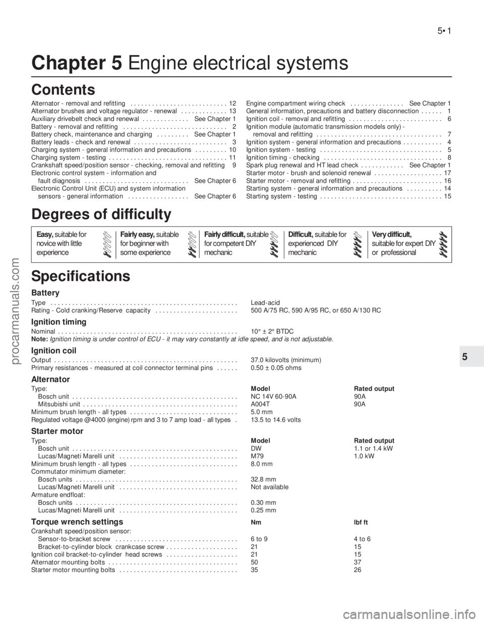
Chapter 5 Engine electrical systems
Alternator - removal and refitting . . . . . . . . . . . . . . . . . . . . . . . . . . . 12
Alternator brushes and voltage regulator - renewal . . . . . . . . . . . . . 13
Auxiliary drivebelt check and renewal . . . . . . . . . . . . . See Chapter 1
Battery - removal and refitting . . . . . . . . . . . . . . . . . . . . . . . . . . . . . 2
Battery check, maintenance and charging . . . . . . . . . See Chapter 1
Battery leads - check and renewal . . . . . . . . . . . . . . . . . . . . . . . . . . 3
Charging system - general information and precautions . . . . . . . . . 10
Charging system - testing . . . . . . . . . . . . . . . . . . . . . . . . . . . . . . . . . 11
Crankshaft speed/position sensor - checking, removal and refitting 9
Electronic control system - information and
fault diagnosis . . . . . . . . . . . . . . . . . . . . . . . . . . . . . See Chapter 6
Electronic Control Unit (ECU) and system information
sensors - general information . . . . . . . . . . . . . . . . . See Chapter 6Engine compartment wiring check . . . . . . . . . . . . . . . See Chapter 1
General information, precautions and battery disconnection . . . . . . 1
Ignition coil - removal and refitting . . . . . . . . . . . . . . . . . . . . . . . . . . 6
Ignition module (automatic transmission models only) -
removal and refitting . . . . . . . . . . . . . . . . . . . . . . . . . . . . . . . . . . . 7
Ignition system - general information and precautions . . . . . . . . . . . 4
Ignition system - testing . . . . . . . . . . . . . . . . . . . . . . . . . . . . . . . . . . 5
Ignition timing - checking . . . . . . . . . . . . . . . . . . . . . . . . . . . . . . . . . 8
Spark plug renewal and HT lead check . . . . . . . . . . . . See Chapter 1
Starter motor - brush and solenoid renewal . . . . . . . . . . . . . . . . . . . 17
Starter motor - removal and refitting . . . . . . . . . . . . . . . . . . . . . . . . . 16
Starting system - general information and precautions . . . . . . . . . . 14
Starting system - testing . . . . . . . . . . . . . . . . . . . . . . . . . . . . . . . . . . 15
Battery
Type . . . . . . . . . . . . . . . . . . . . . . . . . . . . . . . . . . . . . . . . . . . . . . . . . . . . Lead-acid
Rating - Cold cranking/Reserve capacity . . . . . . . . . . . . . . . . . . . . . . . 500 A/75 RC, 590 A/95 RC, or 650 A/130 RC
Ignition timing
Nominal . . . . . . . . . . . . . . . . . . . . . . . . . . . . . . . . . . . . . . . . . . . . . . . . . . 10° ± 2° BTDC
Note:Ignition timing is under control of ECU - it may vary constantly at idle speed, and is not adjustable.
Ignition coil
Output . . . . . . . . . . . . . . . . . . . . . . . . . . . . . . . . . . . . . . . . . . . . . . . . . . . 37.0 kilovolts (minimum)
Primary resistances - measured at coil connector terminal pins . . . . . . 0.50 ± 0.05 ohms
Alternator
Type:Model Rated output
Bosch unit . . . . . . . . . . . . . . . . . . . . . . . . . . . . . . . . . . . . . . . . . . . . . . NC 14V 60-90A 90A
Mitsubishi unit . . . . . . . . . . . . . . . . . . . . . . . . . . . . . . . . . . . . . . . . . . . A004T 90A
Minimum brush length - all types . . . . . . . . . . . . . . . . . . . . . . . . . . . . . . 5.0 mm
Regulated voltage @ 4000 (engine) rpm and 3 to 7 amp load - all types .13.5 to 14.6 volts
Starter motor
Type:Model Rated output
Bosch unit . . . . . . . . . . . . . . . . . . . . . . . . . . . . . . . . . . . . . . . . . . . . . . DW 1.1 or 1.4 kW
Lucas/Magneti Marelli unit . . . . . . . . . . . . . . . . . . . . . . . . . . . . . . . . . M79 1.0 kW
Minimum brush length - all types . . . . . . . . . . . . . . . . . . . . . . . . . . . . . . 8.0 mm
Commutator minimum diameter:
Bosch units . . . . . . . . . . . . . . . . . . . . . . . . . . . . . . . . . . . . . . . . . . . . . 32.8 mm
Lucas/Magneti Marelli unit . . . . . . . . . . . . . . . . . . . . . . . . . . . . . . . . . Not available
Armature endfloat:
Bosch units . . . . . . . . . . . . . . . . . . . . . . . . . . . . . . . . . . . . . . . . . . . . . 0.30 mm
Lucas/Magneti Marelli unit . . . . . . . . . . . . . . . . . . . . . . . . . . . . . . . . . 0.25 mm
Torque wrench settingsNm lbf ft
Crankshaft speed/position sensor:
Sensor-to-bracket screw . . . . . . . . . . . . . . . . . . . . . . . . . . . . . . . . . . 6 to 9 4 to 6
Bracket-to-cylinder block crankcase screw . . . . . . . . . . . . . . . . . . . . 21 15
Ignition coil bracket-to-cylinder head screws . . . . . . . . . . . . . . . . . . . . 21 15
Alternator mounting bolts . . . . . . . . . . . . . . . . . . . . . . . . . . . . . . . . . . . . 50 37
Starter motor mounting bolts . . . . . . . . . . . . . . . . . . . . . . . . . . . . . . . . . 35 26
5•1
Easy,suitable for
novice with little
experienceFairly easy,suitable
for beginner with
some experienceFairly difficult,suitable
for competent DIY
mechanicDifficult,suitable for
experienced DIY
mechanicVery difficult,
suitable for expert DIY
or professional
Degrees of difficulty
Specifications Contents
5
procarmanuals.com
Page 113 of 279
5If you are renewing the battery, make sure
that you get one that’s identical, with the
same dimensions, amperage rating, cold
cranking rating, etc. Dispose of the old battery
in a responsible fashion. Most local authorities
have facilities for the collection and disposal
of such items - batteries contain sulphuric
acid and lead, and should not be simply
thrown out with the household rubbish!
6Refitting is the reverse of the removal
procedure.
Note:See also the relevant Sections of
Chapter 1.
1Periodically inspect the entire length of
each battery lead for damage, cracked or
burned insulation, and corrosion. Poor battery
lead connections can cause starting problems
and decreased engine performance.
2Check the lead-to-terminal connections at
the ends of the leads for cracks, loose wire
strands and corrosion. The presence of white,
fluffy deposits under the insulation at the lead
terminal connection is a sign that the lead is
corroded and should be renewed. Check the
terminals for distortion, missing clamp bolts,
and corrosion.
3When removing the leads, always
disconnect the negative lead first, and
reconnect it last (see Section 1). Even if only
the positive lead is being renewed, be sure to
disconnect the negative lead from the battery
first (see Chapter 1 for further information
regarding battery lead removal).
4Disconnect the old leads from the battery,
then trace each of them to their opposite
ends, and detach them from the starter
solenoid and earth terminals. Note the routing
of each lead, to ensure correct installation.
5If you are renewing either or both of the old
leads, take them with you when buying new
leads. It is vitally important that you replace
the leads with identical parts. Leads have
characteristics that make them easy to
identify: positive leads are usually red, larger
in cross-section, and have a larger-diameter
battery post clamp; earth leads are usually
black, smaller in cross-section and have a
slightly smaller-diameter clamp for the
negative post.
6Clean the threads of the solenoid or earth
connection with a wire brush to remove rust
and corrosion.
7Attach the lead to the solenoid or earth
connection, and tighten the mounting nut/bolt
securely.
8Before connecting a new lead to thebattery, make sure that it reaches the battery
post without having to be stretched.
9Connect the positive lead first, followed by
the negative lead.
General
The ignition system includes the ignition
switch, the battery, the crankshaft speed/
position sensor, the coil, the primary (low
tension/LT) and secondary (high tension/HT)
wiring circuits, and the spark plugs. On models
with automatic transmission, a separate
ignition module is also fitted, its functions
being incorporated in the ECU on models with
manual transmission. The ignition system is
controlled by the engine management
system’s Electronic Control Unit (ECU). Using
data provided by information sensors which
monitor various engine functions (such as
engine speed and piston position, intake air
mass and temperature, engine coolant
temperature, etc.), the ECU ensures a
perfectly-timed spark under all conditions (see
Chapter 6). Note:The ignition timing is under
the full control of the ECU, and cannot be
adjusted - see Section 8 for further details.
Precautions
When working on the ignition system, take
the following precautions:
(a) Do not keep the ignition switch on for more
than 10 seconds if the engine will not start.
(b) If a separate tachometer is ever required
for servicing work, consult a dealer
service department before buying a
tachometer for use with this vehicle -
some tachometers may be incompatible
with this ignition system - and always
connect it in accordance with the
equipment manufacturer’s instructions.
(c) Never connect the ignition coil terminals
to earth. This could result in damage to
the coil and/or the ECU or ignition module
(whichever is fitted).
(d) Do not disconnect the battery when the
engine is running.
(e) Make sure that the ignition module (where
fitted) is properly earthed.
(f) Refer to the warning at the beginning of
the next Section concerning HT voltage.
Warning: Because of the high
voltage generated by the ignition
system, extreme care should be
taken whenever an operation is performed
involving ignition components. This not
only includes the ignition module/ECU, coil
and spark plug (HT) leads, but related
components such as electrical connectors,
tachometer and other test equipment also.Note: This is an initial check of the “ignition
part” of the main engine management system,
to be carried out as part of the preliminary
checks of the complete engine management
system (see Chapter 6).
1If the engine turns over but won’t start,
disconnect the (HT) lead from any spark plug,
and attach it to a calibrated tester (available at
most automotive accessory shops). Connect
the clip on the tester to a good earth - a bolt
or metal bracket on the engine. If you’re
unable to obtain a calibrated ignition tester,
have the check carried out by a Ford dealer
service department or similar. Any other form
of testing (such as jumping a spark from the
end of an HT lead to earth) is not
recommended, because of the risk of
personal injury, or of damage to the
ECU/ignition module (see notes above and in
Section 4).
2Crank the engine and watch the end of the
tester to see if bright blue, well-defined sparks
occur.
3If sparks occur, sufficient voltage is
reaching the plug to fire it. Repeat the check
at the remaining plugs, to ensure that all leads
are sound and that the coil is serviceable.
However, the plugs themselves may be fouled
or faulty, so remove and check them as
described in Chapter 1.
4If no sparks or intermittent sparks occur,
the spark plug lead(s) may be defective -
check them as described in Chapter 1.
5If there’s still no spark, check the coil’s
electrical connector, to make sure it’s clean
and tight. Check for full battery voltage to the
coil at the connector’s centre terminal. The
coil is earthed through the ECU - do not
attempt to check this. Check the coil itself
(see Section 6). Make any necessary repairs,
then repeat the check again.
6The remainder of the system checks should
be left to a dealer service department or other
qualified repair facility, as there is a chance
that the ECU may be damaged if tests are not
performed properly.
Warning: Because of the high
voltage generated by the ignition
system, extreme care should be
taken whenever an operation is performed
involving ignition components. This not
only includes the ignition module/ECU, coil
and spark plug (HT) leads, but related
components such as electrical connectors,
tachometer and other test equipment also.
Check
1Having checked that full battery voltage is
available at the centre terminal of the coil’s
electrical connector (see Section 5),
disconnect the battery negative (earth) lead -
see Section 1.
2Unplug the coil’s electrical connector, if not
already disconnected.
6 Ignition coil -
removal and refitting
5 Ignition system - testing
4 Ignition system - general
information and precautions
3 Battery leads -
check and renewal
Engine electrical systems 5•3
5
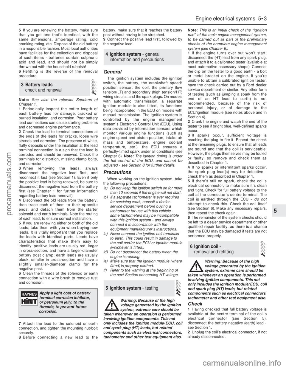
Apply a light coat of battery
terminal corrosion inhibitor,
or petroleum jelly, to the
threads, to prevent future
corrosion.
procarmanuals.com
Page 114 of 279
3Using an ohmmeter, measure the
resistance of the coil’s primary windings,
connecting the meter between the coil’s
terminal pins as follows. Measure first from
one outer pin to the centre pin, then from the
other outer pin to the centre. Compare your
readings with the coil primary resistance listed
in the Specifications Section at the beginning
of this Chapter.
4Disconnect the spark plug (HT) leads - note
their connections or label them carefully, as
described in Chapter 1. Use the meter to
check that there is continuity (ie, a resistance
corresponding to that of the coil secondary
winding) between each pair of (HT) lead
terminals; Nos 1 and 4 terminals are
connected by their secondary winding, as are
Nos 2 and 3. Now switch to the highest
resistance scale, and check that there is no
continuity between either pair of terminals and
the other - ie, there should be infinite
resistance between terminals 1 and 2, or 4
and 3 - and between any terminal and earth.
5If either of the above tests yield resistance
values outside the specified amount, or
results other than those described, renew the
coil. Any further testing should be left to a
dealer service department or other qualified
repair facility.
Removal and refitting
6Disconnect the battery negative (earth) lead
- see Section 1.
7Remove the air mass meter and resonator -
refer to Chapter 4.
8Unplug the electrical connector from each
side of the coil, then disconnect the spark
plug (HT) leads - note their connections or
label them carefully, as described in Chapter
1.
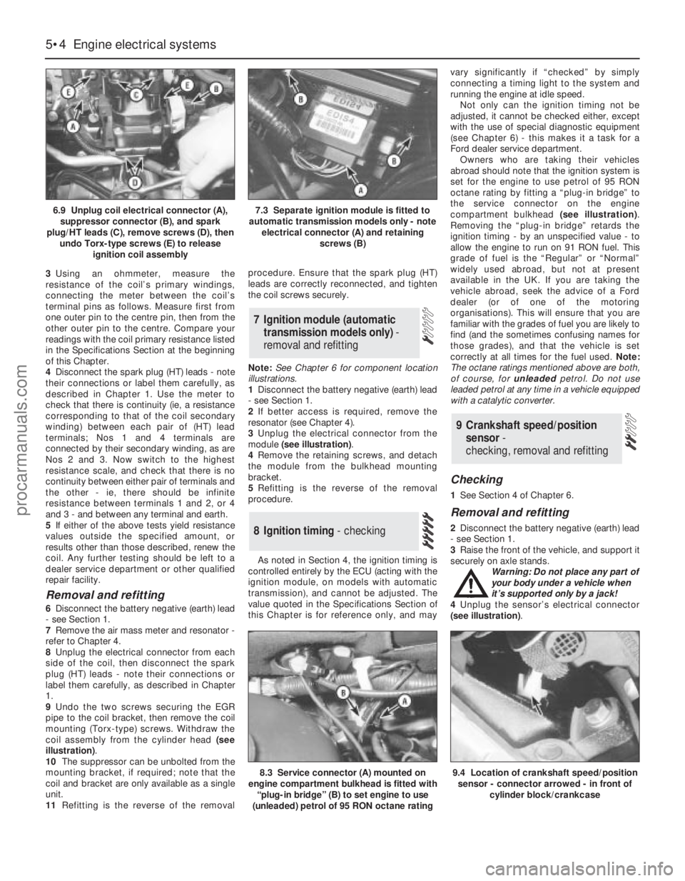
9Undo the two screws securing the EGR
pipe to the coil bracket, then remove the coil
mounting (Torx-type) screws. Withdraw the
coil assembly from the cylinder head (see
illustration).
10The suppressor can be unbolted from the
mounting bracket, if required; note that the
coil and bracket are only available as a single
unit.
11Refitting is the reverse of the removalprocedure. Ensure that the spark plug (HT)
leads are correctly reconnected, and tighten
the coil screws securely.
Note:See Chapter 6 for component location
illustrations.
1Disconnect the battery negative (earth) lead
- see Section 1.
2If better access is required, remove the
resonator (see Chapter 4).
3Unplug the electrical connector from the
module (see illustration).
4Remove the retaining screws, and detach
the module from the bulkhead mounting
bracket.
5Refitting is the reverse of the removal
procedure.
As noted in Section 4, the ignition timing is
controlled entirely by the ECU (acting with the
ignition module, on models with automatic
transmission), and cannot be adjusted. The
value quoted in the Specifications Section of
this Chapter is for reference only, and mayvary significantly if “checked” by simply
connecting a timing light to the system and
running the engine at idle speed.
Not only can the ignition timing not be
adjusted, it cannot be checked either, except
with the use of special diagnostic equipment
(see Chapter 6) - this makes it a task for a
Ford dealer service department.
Owners who are taking their vehicles
abroad should note that the ignition system is
set for the engine to use petrol of 95 RON
octane rating by fitting a “plug-in bridge” to
the service connector on the engine
compartment bulkhead (see illustration).
Removing the “plug-in bridge” retards the
ignition timing - by an unspecified value - to
allow the engine to run on 91 RON fuel. This
grade of fuel is the “Regular” or “Normal”
widely used abroad, but not at present
available in the UK. If you are taking the
vehicle abroad, seek the advice of a Ford
dealer (or of one of the motoring
organisations). This will ensure that you are
familiar with the grades of fuel you are likely to
find (and the sometimes confusing names for
those grades), and that the vehicle is set
correctly at all times for the fuel used. Note:
The octane ratings mentioned above are both,
of course, for unleadedpetrol. Do not use
leaded petrol at any time in a vehicle equipped
with a catalytic converter.
Checking
1See Section 4 of Chapter 6.
Removal and refitting
2Disconnect the battery negative (earth) lead
- see Section 1.
3Raise the front of the vehicle, and support it
securely on axle stands.
Warning: Do not place any part of
your body under a vehicle when
it’s supported only by a jack!
4Unplug the sensor’s electrical connector
(see illustration).
9 Crankshaft speed/position
sensor-
checking, removal and refitting
8 Ignition timing - checking
7 Ignition module (automatic
transmission models only) -
removal and refitting
5•4 Engine electrical systems
6.9 Unplug coil electrical connector (A),
suppressor connector (B), and spark
plug/HT leads (C), remove screws (D), then
undo Torx-type screws (E) to release
ignition coil assembly7.3 Separate ignition module is fitted to
automatic transmission models only - note
electrical connector (A) and retaining
screws (B)
8.3 Service connector (A) mounted on
engine compartment bulkhead is fitted with
“plug-in bridge” (B) to set engine to use
(unleaded) petrol of 95 RON octane rating9.4 Location of crankshaft speed/position
sensor - connector arrowed - in front of
cylinder block/crankcase
procarmanuals.com
Page 115 of 279
5Undo the sensor’s retaining screw and
withdraw the sensor. The sensor’s bracket
cannot be unbolted from the cylinder
block/crankcase unless the transmission and
flywheel/driveplate have been removed (see
Chapter 2).
6Refitting is the reverse of the removal
procedure.
General information
The charging system includes the
alternator, an internal voltage regulator, a no-
charge (or “ignition”) warning light, the
battery, and the wiring between all the
components. The charging system supplies
electrical power for the ignition system, the
lights, the radio, etc. The alternator is driven
by the auxiliary drivebelt at the front (right-
hand end) of the engine.
The purpose of the voltage regulator is to
limit the alternator’s voltage to a preset value.
This prevents power surges, circuit overloads,
etc., during peak voltage output.
The charging system doesn’t ordinarily
require periodic maintenance. However, the
drivebelt, battery and wires and connections
should be inspected at the intervals outlined
in Chapter 1.
The dashboard warning light should come
on when the ignition key is turned to positions
“II” or “III”, then should go off immediately the
engine starts. If it remains on, or if it comes on
while the engine is running, there is a
malfunction in the charging system (see
Section 11). If the light does not come on
when the ignition key is turned, and the bulb is
sound (see Chapter 12), there is a fault in the
alternator.
Precautions
Be very careful when making electrical
circuit connections to a vehicle equipped with
an alternator, and note the following:
(a) When reconnecting wires to the alternator
from the battery, be sure to note the
polarity.
(b) Before using arc-welding equipment to
repair any part of the vehicle, disconnect
the wires from the alternator and the
battery terminals.
(c) Never start the engine with a battery
charger connected.
(d) Always disconnect both battery leads
before using a battery charger.
(e) The alternator is driven by an engine
drivebelt which could cause serious injury
if your hand, hair or clothes become
entangled in it with the engine running.
(f) Because the alternator is connected
directly to the battery, it could arc or
cause a fire if overloaded or shorted-out.
(g) Wrap a plastic bag over the alternator,
and secure it with rubber bands, beforesteam-cleaning or pressure-washing the
engine.
(h) Never disconnect the alternator terminals
while the engine is running.
1If a malfunction occurs in the charging
circuit, don’t automatically assume that the
alternator is causing the problem. First check
the following items:
(a) Check the tension and condition of the
auxiliary drivebelt - renew it if it is worn or
deteriorated (see Chapter 1).
(b) Ensure the alternator mounting bolts and
nuts are tight.
(c) Inspect the alternator wiring harness and
the electrical connections at the
alternator; they must be in good
condition, and tight.
(d) Check the large main fuses in the engine
compartment (see Chapter 12). If any is
blown, determine the cause, repair the
circuit and renew the fuse (the vehicle
won’t start and/or the accessories won’t
work if the fuse is blown).
(e) Start the engine and check the alternator
for abnormal noises - for example, a
shrieking or squealing sound may indicate
a badly-worn bearing or brush.
(f) Make sure that the battery is fully-charged
- one bad cell in a battery can cause
overcharging by the alternator.
(g) Disconnect the battery leads (negative
first, then positive). Inspect the battery
posts and the lead clamps for corrosion.
Clean them thoroughly if necessary (see
Section 3 and Chapter 1). Reconnect the
lead to the negative terminal.
(h) With the ignition and all accessories
switched off, insert a test light between
the battery negative post and the
disconnected negative lead clamp:
(1) If the test light does not come on, re-
attach the clamp and proceed to the next
step.
(2) If the test light comes on, there is a short
in the electrical system of the vehicle. The
short must be repaired before the
charging system can be checked.
(3) To find the short, disconnect the
alternator wiring harness:
(a) If the light goes out, the alternator is
at fault.
(b) If the light stays on, remove each fuse
until it goes out - this will tell you
which component is short-circuited.
2Using a voltmeter, check the battery
voltage with the engine off. It should be
approximately 12 volts.
3Start the engine and check the battery
voltage again. Increase engine speed until the
voltmeter reading remains steady; it should
now be approximately 13.5 to 14.6 volts.
4Switch on as many electrical accessories
(eg the headlights, heated rear window andheater blower) as possible, and check that the
alternator maintains the regulated voltage at
around 13 to 14 volts. The voltage may drop
and then come back up; it may also be
necessary to increase engine speed slightly,
even if the charging system is working
properly.
5If the voltage reading is greater than the
specified charging voltage, renew the voltage
regulator (see Section 13).
6If the voltmeter reading is less than that
specified, the fault may be due to worn
brushes, weak brush springs, a faulty voltage
regulator, a faulty diode, a severed phase
winding, or worn or damaged slip rings. The
brushes and slip rings may be checked (see
Section 13), but if the fault persists, the
alternator should be renewed or taken to an
auto-electrician for testing and repair.
1Disconnect the battery negative (earth) lead
- see Section 1.
2Remove the plenum chamber (see Chap-
ter 4).
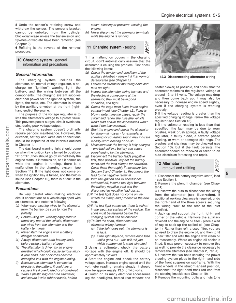
3Unscrew the nuts to disconnect the wiring
from the alternator (see illustration). If
additional working clearance is required, undo
the right-hand of the three screws securing
the wiring “rail” to the rear of the inlet
manifold.
4Jack up and support the front right-hand
corner of the vehicle. Remove the auxiliary
drivebelt and the engine oil filter - place a wad
of rag to soak up the spilled oil (see Chap-
ter 1). Rather than refit a used filter, you are
advised to drain the engine oil, and then to fit
a new filter and refill the engine with clean oil
on reassembly. Where an engine oil cooler is
fitted, it may prove necessary to remove this
as well, to provide the clearance necessary to
remove the alternator (see Chapter 2, Part A).
5Unscrew the two bolts securing the power
steering system pipes to the right-hand side
of the front suspension subframe. With the
front wheels in the straight-ahead position,
disconnect the right-hand track rod end from
the steering knuckle (see Chapter 10).
6Remove the mounting bolts and nuts (one
12 Alternator-
removal and refitting
11 Charging system- testing
10 Charging system - general
information and precautions
Engine electrical systems 5•5
5
12.3 Disconnecting alternator wiring
procarmanuals.com