1993 FORD MONDEO heater
[x] Cancel search: heaterPage 104 of 279
(b) If the pressure is low, pinch the fuel return
line. If the pressure now goes up, renew
the fuel pressure regulator. If the pressure
does not increase, check the fuel feed
line, the fuel pump and the fuel filter.
6Detach the vacuum hose from the fuel
pressure regulator; the pressure shown on the
gauge should increase. Note the increase in
pressure, and compare it with that listed in
this Chapter’s Specifications. If the pressure
increase is not as specified, check the
vacuum hose and pressure regulator.
7Reconnect the regulator vacuum hose, and
switch off the engine. Verify that the fuel
pressure stays at the specified level for five
minutes after the engine is turned off.
8Carefully disconnect the fuel pressure
gauge. Be sure to cover the fitting with a rag
before slackening it. Mop up any spilt petrol.
9Run the engine, and check that there are no
fuel leaks.
Warning: Petrol is extremely
flammable, so take extra
precautions when you work on
any part of the fuel system. Don’t smoke,
or allow open flames or bare light bulbs,
near the work area. Don’t work in a garage
where a natural gas-type appliance (such
as a water heater or clothes dryer) with a
pilot light is present. If you spill any fuel on
your skin, rinse it off immediately with
soap and water. When you perform any
kind of work on the fuel system, wear
safety glasses, and have a Class B type
fire extinguisher on hand.
Note: Ford specify the use of their service tool
23-038 (a large box spanner with projecting teeth
to engage the fuel pump/sender unit retaining
ring’s slots) for this task. While alternatives are
possible, as shown below, in view of the difficulty
experienced in removing and refitting the
pump/sender unit, owners are strongly advised
to obtain this tool before starting work. The help
of an assistant will be required.
1Relieve the residual pressure in the fuel
system (see Section 2), and equalise tank
pressure by removing the fuel filler cap. Warning: This procedure will
merely relieve the increased
pressure necessary for the
engine to run - remember that
fuel will still be present in the system
components, and take precautions
accordingly before disconnecting any of
them.
2Disconnect the battery negative (earth) lead
- see Chapter 5, Section 1.
3Unbolt or fold forwards (as appropriate) the
rear seat base cushion (see Chapter 11).
Withdraw from the vehicle’s floor the grommet
covering the fuel pump/sender unit. Wash off
any dirt from the tank’s top surface, and dry it;
use a vacuum cleaner to clean the immediate
surroundings of the vehicle’s interior, to
reduce the risk of introducing water, dirt and
dust into the tank while it is open.
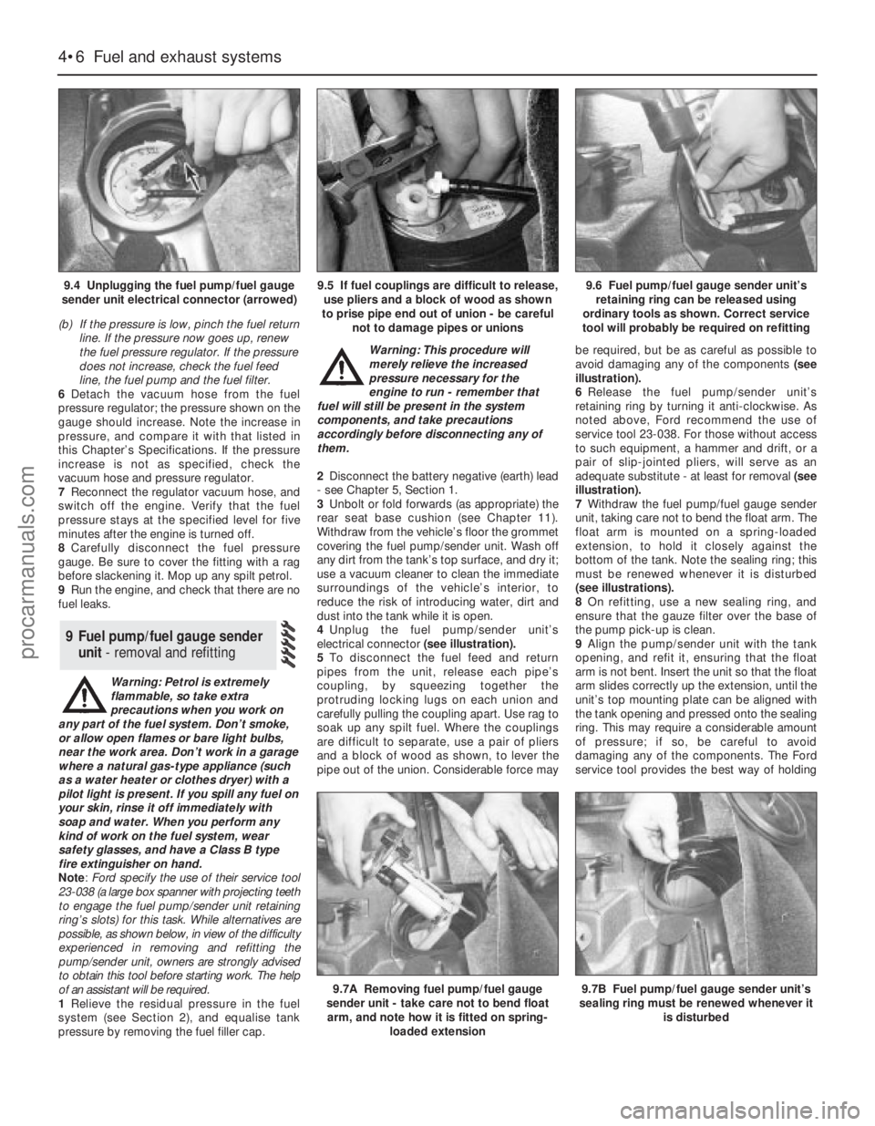
4Unplug the fuel pump/sender unit’s
electrical connector (see illustration).
5To disconnect the fuel feed and return
pipes from the unit, release each pipe’s
coupling, by squeezing together the
protruding locking lugs on each union and
carefully pulling the coupling apart. Use rag to
soak up any spilt fuel. Where the couplings
are difficult to separate, use a pair of pliers
and a block of wood as shown, to lever the
pipe out of the union. Considerable force maybe required, but be as careful as possible to
avoid damaging any of the components (see
illustration).
6Release the fuel pump/sender unit’s
retaining ring by turning it anti-clockwise. As
noted above, Ford recommend the use of
service tool 23-038. For those without access
to such equipment, a hammer and drift, or a
pair of slip-jointed pliers, will serve as an
adequate substitute - at least for removal (see
illustration).
7Withdraw the fuel pump/fuel gauge sender
unit, taking care not to bend the float arm. The
float arm is mounted on a spring-loaded
extension, to hold it closely against the
bottom of the tank. Note the sealing ring; this
must be renewed whenever it is disturbed
(see illustrations).
8On refitting, use a new sealing ring, and
ensure that the gauze filter over the base of
the pump pick-up is clean.
9Align the pump/sender unit with the tank
opening, and refit it, ensuring that the float
arm is not bent. Insert the unit so that the float
arm slides correctly up the extension, until the
unit’s top mounting plate can be aligned with
the tank opening and pressed onto the sealing
ring. This may require a considerable amount
of pressure; if so, be careful to avoid
damaging any of the components. The Ford
service tool provides the best way of holding
9 Fuel pump/fuel gauge sender
unit- removal and refitting
4•6 Fuel and exhaust systems
9.4 Unplugging the fuel pump/fuel gauge
sender unit electrical connector (arrowed)9.5 If fuel couplings are difficult to release,
use pliers and a block of wood as shown
to prise pipe end out of union - be careful
not to damage pipes or unions9.6 Fuel pump/fuel gauge sender unit’s
retaining ring can be released using
ordinary tools as shown. Correct service
tool will probably be required on refitting
9.7A Removing fuel pump/fuel gauge
sender unit - take care not to bend float
arm, and note how it is fitted on spring-
loaded extension9.7B Fuel pump/fuel gauge sender unit’s
sealing ring must be renewed whenever it
is disturbed
procarmanuals.com
Page 105 of 279
the ring square to the tank and turning it at the
same time.
10Maintain the pressure while an assistant
refits and engages the retaining ring. When
the ring is engaged in the tank lugs, turn it
clockwise to tighten it until it is secured.
11The remainder of the refitting procedure is
the reverse of removal. Observe the colour-
coding to ensure that the fuel pipes are
reconnected to the correct unions.
Warning: The fuel system pressure
must be released before any part
of the system is disturbed - see
Section 2. Petrol is extremely
flammable, so take extra precautions when
you work on any part of the fuel system.
Don’t smoke, or allow open flames or bare
light bulbs, near the work area. Don’t work
in a garage where a natural gas-type
appliance (such as a water heater or clothes
dryer) with a pilot light is present. If you spill
any fuel on your skin, rinse it off
immediately with soap and water. When you
perform any kind of work on the fuel
system, wear safety glasses, and have a
Class B type fire extinguisher on hand.
1A fuel tank drain plug is not provided; it is
therefore preferable to carry out the removal
operation when the tank is nearly empty.
Before proceeding, disconnect the battery
negative (earth) lead, and syphon or hand-
pump the remaining fuel from the tank.
Alternatively, disconnect the feed pipe from
the fuel filter (see Chapter 1), and connect a
spare length of hose to this so that when the
ignition is switched on, the fuel pump will
empty the tank into a clean container. If this
approach is adopted, ensure that the
container is large enough to take all the fuel in
the tank, and be careful to take all suitable
precautions to prevent the risk of fire. Note:
Before disconnecting or opening any part of
the fuel system, relieve the residual pressure
(see Section 2), and equalise tank pressure by
removing the fuel filler cap. Also disconnect
the battery negative (earth) lead - see Chap-
ter 5, Section 1.2Unbolt or fold forwards (as appropriate) the
rear seat base cushion (see Chapter 11).
Withdraw from the vehicle’s floor the grommet
covering the fuel pump/sender unit. Unplug
the fuel pump/sender unit’s electrical
connector, and disconnect the fuel return pipe
(coded red) from the unit (see Section 9).
3Raise the rear of the vehicle, and support it
securely on axle stands. Get underneath and
familiarise yourself with the layout of the fuel
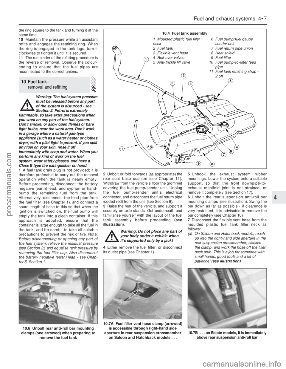
tank assembly before proceeding (see
illustration).
Warning: Do not place any part of
your body under a vehicle when
it’s supported only by a jack!
4Either remove the fuel filter, or disconnect
its outlet pipe (see Chapter 1).5Unhook the exhaust system rubber
mountings. Lower the system onto a suitable
support, so that the front downpipe-to-
exhaust manifold joint is not strained, or
remove it completely (see Section 17).
6Unbolt the rear suspension anti-roll bar
mounting clamps (see illustration). Swing the
bar down as far as possible - if clearance is
very restricted, it is advisable to remove the
bar completely (see Chapter 10).
7Disconnect the flexible vent hose from the
moulded plastic fuel tank filler neck as
follows:
(a) On Saloon and Hatchback models, reach
up into the right-hand side aperture in the
rear suspension crossmember, slacken
the clamp, and work the hose off the filler
neck stub. This is a job for someone with
small hands, good tools and a lot of
patience! (see illustration).
10 Fuel tank -
removal and refitting
Fuel and exhaust systems 4•7
4
10.6 Unbolt rear anti-roll bar mounting
clamps (one arrowed) when preparing to
remove the fuel tank10.7A Fuel filler vent hose clamp (arrowed)
is accessible through right-hand side
aperture in rear suspension crossmember
on Saloon and Hatchback models . . .
10.7B . . . on Estate models, it is immediately
above rear suspension anti-roll bar
10.4 Fuel tank assembly
1 Moulded plastic fuel filler
neck
2 Fuel tank
3 Flexible vent hose
4 Roll-over valves
5 Anti-trickle fill valve6 Fuel pump/fuel gauge
sender unit
7 Fuel return pipe union
8 Heat shield
9 Fuel filter
10 Fuel pump-to-filter feed
pipe
11 Fuel tank retaining strap -
2 off
procarmanuals.com
Page 106 of 279
(b) On Estate models, slacken the clamp
immediately above the rear anti-roll bar,
and work the hose off the filler neck stub
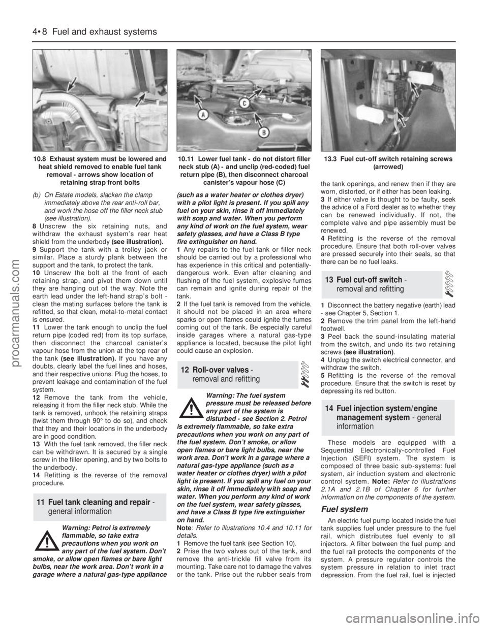
(see illustration).
8Unscrew the six retaining nuts, and
withdraw the exhaust system’s rear heat
shield from the underbody (see illustration).
9Support the tank with a trolley jack or
similar. Place a sturdy plank between the
support and the tank, to protect the tank.
10Unscrew the bolt at the front of each
retaining strap, and pivot them down until
they are hanging out of the way. Note the
earth lead under the left-hand strap’s bolt -
clean the mating surfaces before the tank is
refitted, so that clean, metal-to-metal contact
is ensured.
11Lower the tank enough to unclip the fuel
return pipe (coded red) from its top surface,
then disconnect the charcoal canister’s
vapour hose from the union at the top rear of
the tank (see illustration). If you have any
doubts, clearly label the fuel lines and hoses,
and their respective unions. Plug the hoses, to
prevent leakage and contamination of the fuel
system.
12Remove the tank from the vehicle,
releasing it from the filler neck stub. While the
tank is removed, unhook the retaining straps
(twist them through 90° to do so), and check
that they and their locations in the underbody
are in good condition.
13With the fuel tank removed, the filler neck
can be withdrawn. It is secured by a single
screw in the filler opening, and by two bolts to
the underbody.
14Refitting is the reverse of the removal
procedure.
Warning: Petrol is extremely
flammable, so take extra
precautions when you work on
any part of the fuel system. Don’t
smoke, or allow open flames or bare light
bulbs, near the work area. Don’t work in a
garage where a natural gas-type appliance(such as a water heater or clothes dryer)
with a pilot light is present. If you spill any
fuel on your skin, rinse it off immediately
with soap and water. When you perform
any kind of work on the fuel system, wear
safety glasses, and have a Class B type
fire extinguisher on hand.
1Any repairs to the fuel tank or filler neck
should be carried out by a professional who
has experience in this critical and potentially-
dangerous work. Even after cleaning and
flushing of the fuel system, explosive fumes
can remain and ignite during repair of the
tank.
2If the fuel tank is removed from the vehicle,
it should not be placed in an area where
sparks or open flames could ignite the fumes
coming out of the tank. Be especially careful
inside garages where a natural gas-type
appliance is located, because the pilot light
could cause an explosion.
Warning: The fuel system
pressure must be released before
any part of the system is
disturbed - see Section 2. Petrol
is extremely flammable, so take extra
precautions when you work on any part of
the fuel system. Don’t smoke, or allow
open flames or bare light bulbs, near the
work area. Don’t work in a garage where a
natural gas-type appliance (such as a
water heater or clothes dryer) with a pilot
light is present. If you spill any fuel on your
skin, rinse it off immediately with soap and
water. When you perform any kind of work
on the fuel system, wear safety glasses,
and have a Class B type fire extinguisher
on hand.
Note: Refer to illustrations 10.4 and 10.11 for
details.
1Remove the fuel tank (see Section 10).
2Prise the two valves out of the tank, and
remove the anti-trickle fill valve from its
mounting. Take care not to damage the valves
or the tank. Prise out the rubber seals fromthe tank openings, and renew then if they are
worn, distorted, or if either has been leaking.
3If either valve is thought to be faulty, seek
the advice of a Ford dealer as to whether they
can be renewed individually. If not, the
complete valve and pipe assembly must be
renewed.
4Refitting is the reverse of the removal
procedure. Ensure that both roll-over valves
are pressed securely into their seals, so that
there can be no fuel leaks.
1Disconnect the battery negative (earth) lead
- see Chapter 5, Section 1.
2Remove the trim panel from the left-hand
footwell.
3Peel back the sound-insulating material
from the switch, and undo its two retaining
screws (see illustration).
4Unplug the switch electrical connector, and
withdraw the switch.
5Refitting is the reverse of the removal
procedure. Ensure that the switch is reset by
depressing its red button.
These models are equipped with a
Sequential Electronically-controlled Fuel
Injection (SEFI) system. The system is
composed of three basic sub-systems: fuel
system, air induction system and electronic
control system. Note:Refer to illustrations
2.1A and 2.1B of Chapter 6 for further
information on the components of the system.
Fuel system
An electric fuel pump located inside the fuel
tank supplies fuel under pressure to the fuel
rail, which distributes fuel evenly to all
injectors. A filter between the fuel pump and
the fuel rail protects the components of the
system. A pressure regulator controls the
system pressure in relation to inlet tract
depression. From the fuel rail, fuel is injected
14 Fuel injection system/engine
management system - general
information
13 Fuel cut-off switch -
removal and refitting
12 Roll-over valves -
removal and refitting
11 Fuel tank cleaning and repair -
general information
4•8 Fuel and exhaust systems
10.8 Exhaust system must be lowered and
heat shield removed to enable fuel tank
removal - arrows show location of
retaining strap front bolts10.11 Lower fuel tank - do not distort filler
neck stub (A) - and unclip (red-coded) fuel
return pipe (B), then disconnect charcoal
canister’s vapour hose (C)13.3 Fuel cut-off switch retaining screws
(arrowed)
procarmanuals.com
Page 107 of 279
into the inlet ports, just above the inlet valves,
by four fuel injectors. The system also
includes features such as the flushing of fresh
(ie, cold) fuel around each injector on start-up,
thus improving hot starts.
The amount of fuel supplied by the injectors
is precisely controlled by an Electronic
Control Unit (ECU). The ECU uses the signals
derived from the engine speed/crankshaft
position sensor and the camshaft position
sensor, to trigger each injector separately in
cylinder firing order (sequential injection), with
benefits in terms of better fuel economy and
lower exhaust emissions.
Air induction system
The air system consists of an air filter
housing, an air mass meter, an intake
resonator and plenum chamber, and a throttle
housing. The air mass meter is an information-
gathering device for the ECU; it uses a “hot-
wire” system to send the ECU a constantly-
varying (analogue) voltage signal
corresponding to the volume of air passing
into the engine. Another sensor in the air mass
meter measures intake air temperature. The
ECU uses these signals to calculate the mass
of air entering the engine.
The throttle valve inside the throttle housing
is controlled by the driver, through the
accelerator pedal. As the valve opens, the
amount of air that can pass through the
system increases. The throttle potentiometer
opens further, the air mass meter’s signal
alters, and the ECU opens each injector for a
longer duration, to increase the amount of fuel
delivered to the inlet ports.
Electronic control system
The ECU controls the fuel injection system,
as well as the other sub-systems which make
up the entire engine management system. It
receives signals from a number of information
sensors, which monitor such variables as
intake air mass and temperature, coolant
temperature, engine speed and position,
acceleration/deceleration, and exhaust gas
oxygen content. These signals help the ECU
determine the injection duration necessary for
the optimum air/fuel ratio. These sensors and
associated ECU-controlled relays are located
throughout the engine compartment. For
further information regarding the ECU and its
control of the engine management system,
see Chapter 6.
Idle speed and mixture
adjustment - general
Both the idle speed and mixture are under
the control of the ECU, and cannot be
adjusted. Not only can they not be adjusted,
they cannot even be checked, except with the
use of special diagnostic equipment (see
Chapter 6) - this makes it a task for a Ford
dealer service department. Do notattempt to
“adjust” these settings in any way without
such equipment.
If the idle speed and mixture are thought tobe incorrect, take the vehicle to a Ford dealer
for the complete system to be tested.
On models equipped with a heated
windscreen, an idle-increase solenoid valve is
fitted, which raises the idle speed to
compensate for the increased load on the
engine when the heated windscreen is
switched on. When the valve is open, air from
the plenum chamber bypasses the throttle
housing and idle speed control valve, passing
directly into the inlet manifold through the
union on its left-hand end. The system is
active only for the four minutes that the
heated windscreen circuit is live, and is
supplementary to the main (ECU-controlled)
idle speed regulation.
Warning: Petrol is extremely
flammable, so extra precautions
must be taken when working on
any part of the fuel system. Do
not smoke, or allow open flames or bare
light bulbs, near the work area. Don’t work
in a garage if a natural gas-type appliance
with a pilot light is present. While
performing any work on the fuel system,
wear safety glasses, and have a dry
chemical (Class B) fire extinguisher on
hand. If you spill any fuel on your skin,
rinse it off immediately with soap and
water.
Note: This is an initial check of the fuel delivery
and air induction sub-systems of the engine
management system, to be carried out in
conjunction with the operational check of the
fuel pump (see Section 8), and as part of the
preliminary checks of the complete engine
management system (see Section 3 of
Chapter 6).
1Check the earth wire connections for
tightness. Check all wiring and electrical
connectors that are related to the system.
Loose electrical connectors and poor earths
can cause many problems that resemble
more serious malfunctions.
2Check to see that the battery is fully-
charged. The ECU and sensors depend on an
accurate supply voltage to properly meter the
fuel.
3Check the air filter element - a dirty or
partially-blocked filter will severely impede
performance and economy (see Chapter 1).
4If a blown fuse is found, renew it and see if
it blows again. If it does, search for a short-
circuited wire in the harness related to the
system (see Chapter 6).
5Check the air intake duct from the intake to
the inlet manifold for leaks, which will result in
an excessively-lean mixture. Also check the
condition of the vacuum hoses connected to
the inlet manifold.
6Remove the plenum chamber from the
throttle housing. Check the throttle valve for
dirt, carbon or other residue build-up. If it’sdirty, seek the advice of a Ford dealer - since
the electronic control system is designed to
compensate for factors such as the build-up
of dirt in the throttle housing, it may well be
best to leave it dirty, unless the deposits are
extensive. Note: A warning label on the
housing states specifically that the housing
bore and the throttle valve have a special
coating, and must not be cleaned using
carburettor cleaner, as this may damage it.
7With the engine running, place a
screwdriver or a stethoscope against each
injector, one at a time. Listen through the
screwdriver handle or stethoscope for a
clicking sound, indicating operation.
8If an injector isn’t operating (or sounds
different from the others), turn off the engine,
and unplug the electrical connector from the
injector. Check the resistance across the
terminals of the injector, and compare your
reading with the resistance value listed in this
Chapter’s Specifications. If the resistance
isn’t as specified, renew the injector.
9A rough idle, diminished performance
and/or increased fuel consumption could also
be caused by clogged or fouled fuel injectors.
Fuel additives that can sometimes clean
fouled injectors are available at car accessory
shops.
10The remainder of the system checks
should be left to a dealer service department
or other qualified repair specialist, as there is
a chance that the ECU may be damaged if
tests are not performed properly.
Warning: The fuel system
pressure must be released before
any part of the system is
disturbed - see Section 2. Petrol
is extremely flammable, so take extra
precautions when you work on any part of
the fuel system. Don’t smoke, or allow
open flames or bare light bulbs, near the
work area. Don’t work in a garage where a
natural gas-type appliance (such as a
water heater or clothes dryer) with a pilot
light is present. If you spill any fuel on your
skin, rinse it off immediately with soap and
water. When you perform any kind of work
on the fuel system, wear safety glasses,
and have a Class B type fire extinguisher
on hand.
Throttle housing
Check
1Remove the plenum chamber (see Sec-
tion 4), and verify that the throttle linkage
operates smoothly.
2If the housing bore and valve are dirty
enough for you to think that this might be the
cause of a fault, seek the advice of a Ford
dealer. Do notclean the housing (see the
notes in the checking procedure given in
Section 15).
16 Fuel system components-
check and renewal
15 Fuel injection system/engine
management system - check
Fuel and exhaust systems 4•9
4
procarmanuals.com
Page 115 of 279
5Undo the sensor’s retaining screw and
withdraw the sensor. The sensor’s bracket
cannot be unbolted from the cylinder
block/crankcase unless the transmission and
flywheel/driveplate have been removed (see
Chapter 2).
6Refitting is the reverse of the removal
procedure.
General information
The charging system includes the
alternator, an internal voltage regulator, a no-
charge (or “ignition”) warning light, the
battery, and the wiring between all the
components. The charging system supplies
electrical power for the ignition system, the
lights, the radio, etc. The alternator is driven
by the auxiliary drivebelt at the front (right-
hand end) of the engine.
The purpose of the voltage regulator is to
limit the alternator’s voltage to a preset value.
This prevents power surges, circuit overloads,
etc., during peak voltage output.
The charging system doesn’t ordinarily
require periodic maintenance. However, the
drivebelt, battery and wires and connections
should be inspected at the intervals outlined
in Chapter 1.
The dashboard warning light should come
on when the ignition key is turned to positions
“II” or “III”, then should go off immediately the
engine starts. If it remains on, or if it comes on
while the engine is running, there is a
malfunction in the charging system (see
Section 11). If the light does not come on
when the ignition key is turned, and the bulb is
sound (see Chapter 12), there is a fault in the
alternator.
Precautions
Be very careful when making electrical
circuit connections to a vehicle equipped with
an alternator, and note the following:
(a) When reconnecting wires to the alternator
from the battery, be sure to note the
polarity.
(b) Before using arc-welding equipment to
repair any part of the vehicle, disconnect
the wires from the alternator and the
battery terminals.
(c) Never start the engine with a battery
charger connected.
(d) Always disconnect both battery leads
before using a battery charger.
(e) The alternator is driven by an engine
drivebelt which could cause serious injury
if your hand, hair or clothes become
entangled in it with the engine running.
(f) Because the alternator is connected
directly to the battery, it could arc or
cause a fire if overloaded or shorted-out.
(g) Wrap a plastic bag over the alternator,
and secure it with rubber bands, beforesteam-cleaning or pressure-washing the
engine.
(h) Never disconnect the alternator terminals
while the engine is running.
1If a malfunction occurs in the charging
circuit, don’t automatically assume that the
alternator is causing the problem. First check
the following items:
(a) Check the tension and condition of the
auxiliary drivebelt - renew it if it is worn or
deteriorated (see Chapter 1).
(b) Ensure the alternator mounting bolts and
nuts are tight.
(c) Inspect the alternator wiring harness and
the electrical connections at the
alternator; they must be in good
condition, and tight.
(d) Check the large main fuses in the engine
compartment (see Chapter 12). If any is
blown, determine the cause, repair the
circuit and renew the fuse (the vehicle
won’t start and/or the accessories won’t
work if the fuse is blown).
(e) Start the engine and check the alternator
for abnormal noises - for example, a
shrieking or squealing sound may indicate
a badly-worn bearing or brush.
(f) Make sure that the battery is fully-charged
- one bad cell in a battery can cause
overcharging by the alternator.
(g) Disconnect the battery leads (negative
first, then positive). Inspect the battery
posts and the lead clamps for corrosion.
Clean them thoroughly if necessary (see
Section 3 and Chapter 1). Reconnect the
lead to the negative terminal.
(h) With the ignition and all accessories
switched off, insert a test light between
the battery negative post and the
disconnected negative lead clamp:
(1) If the test light does not come on, re-
attach the clamp and proceed to the next
step.
(2) If the test light comes on, there is a short
in the electrical system of the vehicle. The
short must be repaired before the
charging system can be checked.
(3) To find the short, disconnect the
alternator wiring harness:
(a) If the light goes out, the alternator is
at fault.
(b) If the light stays on, remove each fuse
until it goes out - this will tell you
which component is short-circuited.
2Using a voltmeter, check the battery
voltage with the engine off. It should be
approximately 12 volts.
3Start the engine and check the battery
voltage again. Increase engine speed until the
voltmeter reading remains steady; it should
now be approximately 13.5 to 14.6 volts.
4Switch on as many electrical accessories
(eg the headlights, heated rear window andheater blower) as possible, and check that the
alternator maintains the regulated voltage at
around 13 to 14 volts. The voltage may drop
and then come back up; it may also be
necessary to increase engine speed slightly,
even if the charging system is working
properly.
5If the voltage reading is greater than the
specified charging voltage, renew the voltage
regulator (see Section 13).
6If the voltmeter reading is less than that
specified, the fault may be due to worn
brushes, weak brush springs, a faulty voltage
regulator, a faulty diode, a severed phase
winding, or worn or damaged slip rings. The
brushes and slip rings may be checked (see
Section 13), but if the fault persists, the
alternator should be renewed or taken to an
auto-electrician for testing and repair.
1Disconnect the battery negative (earth) lead
- see Section 1.
2Remove the plenum chamber (see Chap-
ter 4).
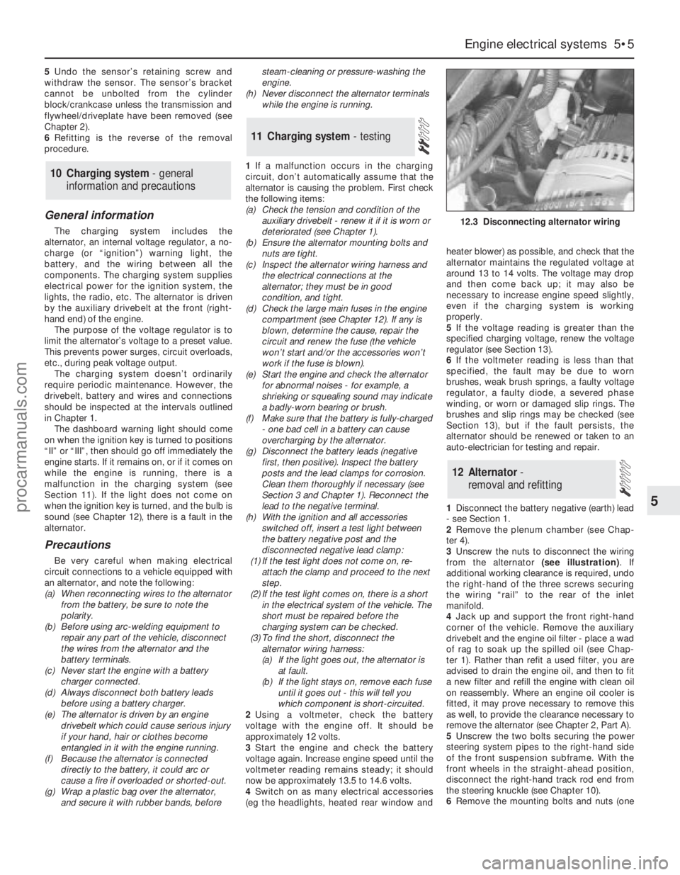
3Unscrew the nuts to disconnect the wiring
from the alternator (see illustration). If
additional working clearance is required, undo
the right-hand of the three screws securing
the wiring “rail” to the rear of the inlet
manifold.
4Jack up and support the front right-hand
corner of the vehicle. Remove the auxiliary
drivebelt and the engine oil filter - place a wad
of rag to soak up the spilled oil (see Chap-
ter 1). Rather than refit a used filter, you are
advised to drain the engine oil, and then to fit
a new filter and refill the engine with clean oil
on reassembly. Where an engine oil cooler is
fitted, it may prove necessary to remove this
as well, to provide the clearance necessary to
remove the alternator (see Chapter 2, Part A).
5Unscrew the two bolts securing the power
steering system pipes to the right-hand side
of the front suspension subframe. With the
front wheels in the straight-ahead position,
disconnect the right-hand track rod end from
the steering knuckle (see Chapter 10).
6Remove the mounting bolts and nuts (one
12 Alternator-
removal and refitting
11 Charging system- testing
10 Charging system - general
information and precautions
Engine electrical systems 5•5
5
12.3 Disconnecting alternator wiring
procarmanuals.com
Page 132 of 279
Note:If any part of the ABS hydraulic unit is
defective, it must be renewed as an assembly.
Apart from the relay box (Section 22),
individual spare parts are not available.
Removal
1Remove both pressure-control relief valves
as described in Section 19.
2Identify the location of the remaining brake
hydraulic pipes on the ABS hydraulic unit,
then unscrew the union nuts and pull out the
pipes. Carefully bend the pipes away from the
hydraulic unit, to allow the unit to be removed.
3Disconnect the multi-plugs from the
hydraulic unit. To disconnect the main 22-pin
multi-plug, push the locktab, then swivel the
multi-plug outwards and unhook it.
Right-hand drive models
4Have an assistant hold the brake pedal
depressed, then extract the spring clip and
remove the clevis pin securing the servo unit
pushrod to the pedal cross-link arm.
5Remove the vacuum servo unit from the
engine compartment.
Left-hand drive models
6Unscrew the nut securing the pedal
trunnion to the servo unit pushrod inside the
passenger compartment. The nut is located
near the top of the pedal, and is accessible
through an access hole. For improved access,
remove the lower facia panel first.
7Remove the vacuum servo unit, together
with the pushrod, from the engine
compartment. Take care not to damage the
rubber grommet in the bulkhead.
All models
8Unscrew the pump mounting nut.
9Raise the left-hand side of the ABS
hydraulic unit, then swivel the unit out of the
right-hand mounting. Take care not to lose the
bracket studs and insulator ring.
Refitting
10Locate the insulator ring on the pump
end, and fit the stud cap to the insulator ring.
11Lower the ABS hydraulic unit into
position, right-hand end first.
12Fit the right-hand bracket studs onto the
insulators.
13Lower the left-hand end of the ABS
hydraulic unit onto the bracket, then fit and
tighten the pump mounting nut.
Left-hand drive models
14Locate the vacuum servo unit and
pushrod on the bulkhead bracket, taking care
not to damage the rubber grommet.
15Insert the pushrod in the pedal trunnion,
and tighten the nut.
16Refit the lower facia panel if it was
removed.
Right-hand drive models
17Locate the vacuum servo unit and
pushrod on the bulkhead bracket.
18Refit the clevis pin and spring clip
securing the servo unit pushrod to the pedal
cross-link arm.
All models
19Reconnect the multi-plugs to the
hydraulic unit.
20Reconnect the brake pipes to the
hydraulic unit, and tighten the union nuts.
21Refit both pressure-control relief valves,
with reference to Section 20.
Testing
1Checking of the sensors is done before
removal, connecting a voltmeter to the
disconnected sensor multi-plug. Using an
analogue (moving coil) meter is not practical,
since the meter does not respond quickly
enough. A digital meter having an AC facility
may be used to check that the sensor is
operating correctly. To do this, raise the
relevant wheel then disconnect the wiring to
the ABS sensor and connect the meter to it.
Spin the wheel and check that the output
voltage is between 1.5 and 2.0 volts,
depending on how fast the wheel is spun.
Alternatively, an oscilloscope may be used to
check the output of the sensor - an alternating
current will be traced on the screen, of
magnitude depending on the speed of the
rotating wheel.
2If the sensor output is low or zero, renew
the sensor.
Removal
Front wheel sensor
3Apply the handbrake, jack up the front of
the vehicle and support it on axle stands.
Remove the relevant wheel.
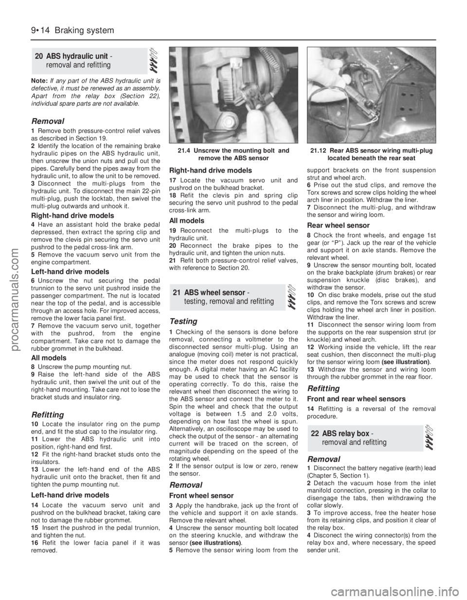
4Unscrew the sensor mounting bolt located
on the steering knuckle, and withdraw the
sensor (see illustrations).
5Remove the sensor wiring loom from thesupport brackets on the front suspension
strut and wheel arch.
6Prise out the stud clips, and remove the
Torx screws and screw clips holding the wheel
arch liner in position. Withdraw the liner.
7Disconnect the multi-plug, and withdraw
the sensor and wiring loom.
Rear wheel sensor
8Chock the front wheels, and engage 1st
gear (or “P”). Jack up the rear of the vehicle
and support it on axle stands. Remove the
relevant wheel.
9Unscrew the sensor mounting bolt, located
on the brake backplate (drum brakes) or rear
suspension knuckle (disc brakes), and
withdraw the sensor.
10On disc brake models, prise out the stud
clips, and remove the Torx screws and screw
clips holding the wheel arch liner in position.
Withdraw the liner.
11Disconnect the sensor wiring loom from
the supports on the rear suspension strut (or
knuckle) and wheel arch.
12Working inside the vehicle, lift the rear
seat cushion, then disconnect the multi-plug
for the sensor wiring loom (see illustration).
13Withdraw the sensor and wiring loom
through the rubber grommet in the rear floor.
Refitting
Front and rear wheel sensors
14Refitting is a reversal of the removal
procedure.
Removal
1Disconnect the battery negative (earth) lead
(Chapter 5, Section 1).
2Detach the vacuum hose from the inlet
manifold connection, pressing in the collar to
disengage the tabs, then withdrawing the
collar slowly.
3To improve access, free the heater hose
from its retaining clips, and position it clear of
the relay box.
4Disconect the wiring connector(s) from the
relay box and, where necessary, the speed
sender unit.
22 ABS relay box -
removal and refitting
21 ABS wheel sensor -
testing, removal and refitting
20 ABS hydraulic unit -
removal and refitting
9•14 Braking system
21.4 Unscrew the mounting bolt and
remove the ABS sensor21.12 Rear ABS sensor wiring multi-plug
located beneath the rear seat
procarmanuals.com
Page 180 of 279
Mats and carpets should be brushed or
vacuum-cleaned regularly, to keep them free
of grit. If they are badly stained, remove them
from the vehicle for scrubbing or sponging,
and make quite sure they are dry before
refitting. Seats and interior trim panels can be
kept clean by wiping with a damp cloth. If they
do become stained (which can be more
apparent on light-coloured upholstery), use a
little liquid detergent and a soft nail brush to
scour the grime out of the grain of the
material. Do not forget to keep the headlining
clean in the same way as the upholstery.
When using liquid cleaners inside the vehicle,
do not over-wet the surfaces being cleaned.
Excessive damp could get into the seams and
padded interior, causing stains, offensive
odours or even rot.
Note:For more detailed information about
bodywork repair, Haynes Publishing produce
a book by Lindsay Porter called “The Car
Bodywork Repair Manual”. This incorporates
information on such aspects as rust treatment,
painting and glass-fibre repairs, as well as
details on more ambitious repairs involving
welding and panel beating.
Repairs of minor scratches in
bodywork
If the scratch is very superficial, and does
not penetrate to the metal of the bodywork,
repair is very simple. Lightly rub the area of
the scratch with a paintwork renovator, or a
very fine cutting paste, to remove loose paint
from the scratch, and to clear the surrounding
bodywork of wax polish. Rinse the area with
clean water.
Apply touch-up paint to the scratch using a
fine paint brush; continue to apply fine layers
of paint until the surface of the paint in the
scratch is level with the surrounding
paintwork. Allow the new paint at least two
weeks to harden, then blend it into the
surrounding paintwork by rubbing the scratch
area with a paintwork renovator or a very fine
cutting paste. Finally, apply wax polish.
Where the scratch has penetrated right
through to the metal of the bodywork, causingthe metal to rust, a different repair technique
is required. Remove any loose rust from the
bottom of the scratch with a penknife, then
apply rust-inhibiting paint to prevent the
formation of rust in the future. Using a rubber
or nylon applicator, fill the scratch with
bodystopper paste. If required, this paste can
be mixed with cellulose thinners to provide a
very thin paste which is ideal for filling narrow
scratches. Before the stopper-paste in the
scratch hardens, wrap a piece of smooth
cotton rag around the top of a finger. Dip the
finger in cellulose thinners, and quickly sweep
it across the surface of the stopper-paste in
the scratch; this will ensure that the surface of
the stopper-paste is slightly hollowed. The
scratch can now be painted over as described
earlier in this Section.
Repairs of dents in bodywork
When deep denting of the vehicle’s
bodywork has taken place, the first task is to
pull the dent out, until the affected bodywork
almost attains its original shape. There is little
point in trying to restore the original shape
completely, as the metal in the damaged area
will have stretched on impact, and cannot be
reshaped fully to its original contour. It is
better to bring the level of the dent up to a
point which is about 3 mm below the level of
the surrounding bodywork. In cases where the
dent is very shallow anyway, it is not worth
trying to pull it out at all. If the underside of the
dent is accessible, it can be hammered out
gently from behind, using a mallet with a
wooden or plastic head. Whilst doing this,
hold a suitable block of wood firmly against
the outside of the panel, to absorb the impact
from the hammer blows and thus prevent a
large area of the bodywork from being
“belled-out”.
Should the dent be in a section of the
bodywork which has a double skin, or some
other factor making it inaccessible from
behind, a different technique is called for. Drill
several small holes through the metal inside
the area - particularly in the deeper section.
Then screw long self-tapping screws into the
holes, just sufficiently for them to gain a good
purchase in the metal. Now the dent can be
pulled out by pulling on the protruding heads
of the screws with a pair of pliers.
The next stage of the repair is the removal
of the paint from the damaged area, and from
an inch or so of the surrounding “sound”
bodywork. This is accomplished most easily
by using a wire brush or abrasive pad on a
power drill, although it can be done just as
effectively by hand, using sheets of abrasive
paper. To complete the preparation for filling,
score the surface of the bare metal with a
screwdriver or the tang of a file, or
alternatively, drill small holes in the affected
area. This will provide a really good “key” for
the filler paste.
To complete the repair, see the Section on
filling and respraying.
Repairs of rust holes or gashes in
bodywork
Remove all paint from the affected area,
and from an inch or so of the surrounding
“sound” bodywork, using an abrasive pad or a
wire brush on a power drill. If these are not
available, a few sheets of abrasive paper will
do the job most effectively. With the paint
removed, you will be able to judge the severity
of the corrosion, and therefore decide
whether to renew the whole panel (if this is
possible) or to repair the affected area. New
body panels are not as expensive as most
people think, and it is often quicker and more
satisfactory to fit a new panel than to attempt
to repair large areas of corrosion.
Remove all fittings from the affected area,
except those which will act as a guide to the
original shape of the damaged bodywork (eg
headlight shells etc). Then, using tin snips or a
hacksaw blade, remove all loose metal and any
other metal badly affected by corrosion.
Hammer the edges of the hole inwards, in order
to create a slight depression for the filler paste.
Wire-brush the affected area to remove the
powdery rust from the
surface of the remaining metal. Paint the
affected area with rust-inhibiting paint, if the
back of the rusted area is accessible, treat
this also.
Before filling can take place, it will be
necessary to block the hole in some way. This
can be achieved by the use of aluminium or
plastic mesh, or aluminium tape.
Aluminium or plastic mesh, or glass-fibre
matting, is probably the best material to use
for a large hole. Cut a piece to the
approximate size and shape of the hole to be
filled, then position it in the hole so that its
edges are below the level of the surrounding
bodywork. It can be retained in position by
several blobs of filler paste around its
periphery.
Aluminium tape should be used for small or
very narrow holes. Pull a piece off the roll, trim
it to the approximate size and shape required,
then pull off the backing paper (if used) and
stick the tape over the hole; it can be
overlapped if the thickness of one piece is
insufficient. Burnish down the edges of the
tape with the handle of a screwdriver or
similar, to ensure that the tape is securely
attached to the metal underneath.
Bodywork repairs - filling and
respraying
Before using this Section, see the Sections
on dent, deep scratch, rust holes and gash
repairs.
Many types of bodyfiller are available, but
generally speaking, those proprietary kits
which contain a tin of filler paste and a tube of
resin hardener are best for this type of repair.
A wide, flexible plastic or nylon applicator will
be found invaluable for imparting a smooth
and well-contoured finish to the surface of the
filler.
4 Minor body damage - repair
3 Maintenance -
upholstery and carpets
Bodywork and fittings 11•3
11
If the inside of the vehicle
gets wet accidentally, it is
worthwhile taking some
trouble to dry it out properly,
particularly where carpets are involved.
Do not leave oil or electric heaters
inside the vehicle for this purpose.
procarmanuals.com
Page 200 of 279
Removal
1Disconnect the battery negative (earth) lead
(Chapter 5, Section 1).
2Remove the windscreen wiper arms
(Chapter 12), then remove the cowl from just
in front of the windscreen. The cowl is in two
sections, with retaining screws located along
its front edge. With the cowl removed,
disconnect the speedometer cable by pulling
it from the intermediate inner cable extension.
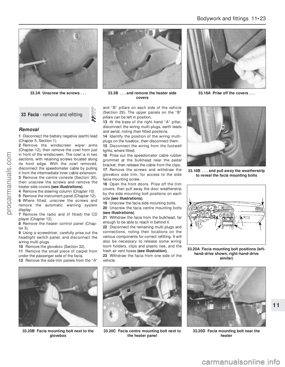
3Remove the centre console (Section 30),
then unscrew the screws and remove the
heater side covers (see illustrations).
4Remove the steering column (Chapter 10).
5Remove the instrument panel (Chapter 12).
6Where fitted, unscrew the screws and
remove the automatic warning system
display.
7Remove the radio and (if fitted) the CD
player (Chapter 12).
8Remove the heater control panel (Chap-
ter 3).
9Using a screwdriver, carefully prise out the
headlight switch panel, and disconnect the
wiring multi-plugs.
10Remove the glovebox (Section 32).
11Remove the small piece of carpet from
under the passenger side of the facia.
12Remove the side trim panels from the “A”and “B” pillars on each side of the vehicle
(Section 29). The upper panels on the “B”
pillars can be left in position.
13At the base of the right-hand “A” pillar,
disconnect the wiring multi-plugs, earth leads
and aerial, noting their fitted positions.
14Identify the position of the wiring multi-
plugs on the fusebox, then disconnect them.
15Disconnect the wiring from the footwell
lights, where fitted.
16Prise out the speedometer cable rubber
grommet at the bulkhead near the pedal
bracket, then release the cable from the clips.
17Remove the screws and withdraw the
glovebox side trim, for access to the side
facia mounting screw.
18Open the front doors. Prise off the trim
covers, then pull away the door weatherstrip
by the side mounting bolt positions on each
side (see illustrations).
19Unscrew the facia side mounting bolts.
20Unscrew the facia centre mounting bolts
(see illustrations).
21Withdraw the facia from the bulkhead, far
enough to be able to reach in behind it.
22Disconnect the remaining multi-plugs and
connections, noting their locations on the
various components for correct refitting. It will
also be necessary to release some wiring
loom holders, clips and plastic ties, and the
fresh air vent hoses (see illustration).
23Withdraw the facia from one side of the
vehicle.
33 Facia - removal and refitting
Bodywork and fittings 11•23
11
33.20B Facia mounting bolt next to the
glovebox33.20C Facia centre mounting bolt next to
the heater panel33.20D Facia mounting bolt near the
heater
33.3A Unscrew the screws . . .33.3B . . . and remove the heater side
covers33.18A Prise off the covers . . .
33.18B . . . and pull away the weatherstrip
to reveal the facia mounting bolts
33.20A Facia mounting bolt positions (left-
hand-drive shown, right-hand-drive
similar)
procarmanuals.com