1993 FORD MONDEO heater
[x] Cancel search: heaterPage 203 of 279
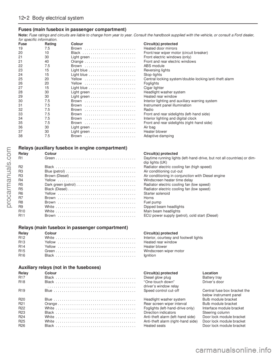
Fuses (main fusebox in passenger compartment)
Note:Fuse ratings and circuits are liable to change from year to year. Consult the handbook supplied with the vehicle, or consult a Ford dealer,
for specific information.
Fuse Rating Colour Circuit(s) protected
19 7.5 Brown . . . . . . . . . . . . . . . . . . . . . . . . . Heated door mirrors
20 10 Black . . . . . . . . . . . . . . . . . . . . . . . . . . Front/rear wiper motor (circuit breaker)
21 30 Light green . . . . . . . . . . . . . . . . . . . . . . Front electric windows (only)
21 40 Orange . . . . . . . . . . . . . . . . . . . . . . . . . Front and rear electric windows
22 7.5 Brown . . . . . . . . . . . . . . . . . . . . . . . . . ABS module
23 15 Light blue . . . . . . . . . . . . . . . . . . . . . . . Reversing lights
24 15 Light blue . . . . . . . . . . . . . . . . . . . . . . . Stop-lights
25 20 Yellow . . . . . . . . . . . . . . . . . . . . . . . . . Central locking system/double-locking/anti-theft alarm
26 20 Yellow . . . . . . . . . . . . . . . . . . . . . . . . . Foglights
27 15 Light blue . . . . . . . . . . . . . . . . . . . . . . . Cigar lighter
28 30 Light green . . . . . . . . . . . . . . . . . . . . . . Headlight washer system
29 30 Light green . . . . . . . . . . . . . . . . . . . . . . Heated rear window
30 7.5 Brown . . . . . . . . . . . . . . . . . . . . . . . . . Interior lighting and auxiliary warning system
31 7.5 Brown . . . . . . . . . . . . . . . . . . . . . . . . . Instrument panel illumination
32 7.5 Brown . . . . . . . . . . . . . . . . . . . . . . . . . Radio
33 7.5 Brown . . . . . . . . . . . . . . . . . . . . . . . . . Front and rear sidelights (left-hand side)
34 7.5 Brown . . . . . . . . . . . . . . . . . . . . . . . . . Interior lighting and digital clock
35 7.5 Brown . . . . . . . . . . . . . . . . . . . . . . . . . Front and rear sidelights (right-hand side)
36 30 Light green . . . . . . . . . . . . . . . . . . . . . . Air bag
37 30 Light green . . . . . . . . . . . . . . . . . . . . . . Heater blower
38 7.5 Brown . . . . . . . . . . . . . . . . . . . . . . . . . Adaptive damping
Relays (auxiliary fusebox in engine compartment)
Relay Colour Circuit(s) protected
R1 Green . . . . . . . . . . . . . . . . . . . . . . . . . . . . . . . . . . . . . . . Daytime running lights (left-hand-drive, but not all countries) or dim-
dip lights (UK)
R2 Black . . . . . . . . . . . . . . . . . . . . . . . . . . . . . . . . . . . . . . . Radiator electric cooling fan (high speed)
R3 Blue (petrol) . . . . . . . . . . . . . . . . . . . . . . . . . . . . . . . . . . Air conditioning cut-out
R3 Brown (Diesel) . . . . . . . . . . . . . . . . . . . . . . . . . . . . . . . . Air conditioning in conjunction with Diesel engine
R4 Yellow . . . . . . . . . . . . . . . . . . . . . . . . . . . . . . . . . . . . . . Windscreen heater time delay
R5 Dark green (petrol) . . . . . . . . . . . . . . . . . . . . . . . . . . . . . Radiator electric cooling fan (low speed)
R5 Black (Diesel) . . . . . . . . . . . . . . . . . . . . . . . . . . . . . . . . . Radiator electric cooling fan (low speed)
R6 Yellow . . . . . . . . . . . . . . . . . . . . . . . . . . . . . . . . . . . . . . Starter solenoid
R7 Brown . . . . . . . . . . . . . . . . . . . . . . . . . . . . . . . . . . . . . . Horns
R8 Brown . . . . . . . . . . . . . . . . . . . . . . . . . . . . . . . . . . . . . . Fuel pump
R9 White . . . . . . . . . . . . . . . . . . . . . . . . . . . . . . . . . . . . . . . Dipped beam headlights
R10 White . . . . . . . . . . . . . . . . . . . . . . . . . . . . . . . . . . . . . . . Main beam headlights
R11 Brown . . . . . . . . . . . . . . . . . . . . . . . . . . . . . . . . . . . . . . ECU power supply (petrol), cold start (Diesel)
Relays (main fusebox in passenger compartment)
Relay Colour Circuit(s) protected
R12 White . . . . . . . . . . . . . . . . . . . . . . . . . . . . . . . . . . . . . . . Interior, courtesy and footwell lights
R13 Yellow . . . . . . . . . . . . . . . . . . . . . . . . . . . . . . . . . . . . . . Heated rear window
R14 Yellow . . . . . . . . . . . . . . . . . . . . . . . . . . . . . . . . . . . . . . Heater blower
R15 Green . . . . . . . . . . . . . . . . . . . . . . . . . . . . . . . . . . . . . . . Windscreen wiper motor
R16 Black . . . . . . . . . . . . . . . . . . . . . . . . . . . . . . . . . . . . . . . Ignition
Auxiliary relays (not in the fuseboxes)
Relay Colour Circuit(s) protected Location
R17 Black . . . . . . . . . . . . . . . . . . . . . . . . . . . . . . . . . . . . . . . Diesel glow plug Battery tray
R18 Black . . . . . . . . . . . . . . . . . . . . . . . . . . . . . . . . . . . . . . . “One-touch down” Driver’s door
. . . . . . . . . . . . . . . . . . . . . . . . . . . . . . . . . . . . . . . . . . . driver’s window relay
R19 Blue . . . . . . . . . . . . . . . . . . . . . . . . . . . . . . . . . . . . . . . . Speed control cut-off Central fuse box bracket the
below instrument panel
R20 Blue . . . . . . . . . . . . . . . . . . . . . . . . . . . . . . . . . . . . . . . . Headlight washer system Bulb module bracket
R21 Orange . . . . . . . . . . . . . . . . . . . . . . . . . . . . . . . . . . . . . . Rear screen wiper interval Bulb module bracket
R22 White . . . . . . . . . . . . . . . . . . . . . . . . . . . . . . . . . . . . . . . Foglights (left-hand-drive only) Interface module bracket
R23 Black . . . . . . . . . . . . . . . . . . . . . . . . . . . . . . . . . . . . . . . Direction indicators Steering column
R24 White . . . . . . . . . . . . . . . . . . . . . . . . . . . . . . . . . . . . . . . Anti-theft alarm (left-hand side) Door lock module bracket
R25 White . . . . . . . . . . . . . . . . . . . . . . . . . . . . . . . . . . . . . . . Anti-theft alarm (right-hand side) Door lock module bracket
R26 Black . . . . . . . . . . . . . . . . . . . . . . . . . . . . . . . . . . . . . . . Heated seats Door lock module bracket
12•2 Body electrical system
procarmanuals.com
Page 212 of 279
Engine compartment light
1With the bonnet open, pull the wedge-type
bulb from the bulbholder.
2Fit the new bulb using a reversal of the
removal procedure.
Interior lights
3Switch off the interior light by locating the
switch in its middle position.
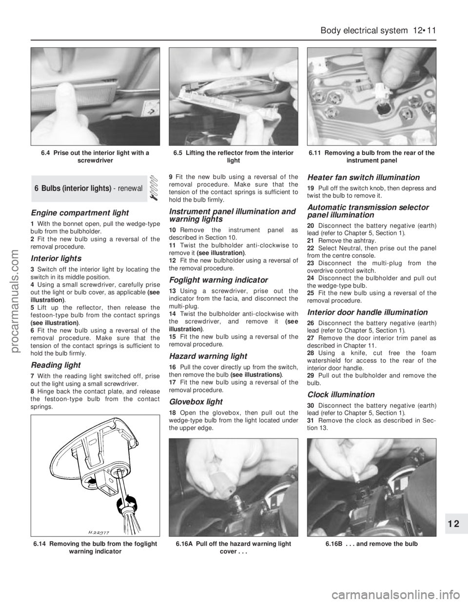
4Using a small screwdriver, carefully prise
out the light or bulb cover, as applicable (see
illustration).
5Lift up the reflector, then release the
festoon-type bulb from the contact springs
(see illustration).
6Fit the new bulb using a reversal of the
removal procedure. Make sure that the
tension of the contact springs is sufficient to
hold the bulb firmly.
Reading light
7With the reading light switched off, prise
out the light using a small screwdriver.
8Hinge back the contact plate, and release
the festoon-type bulb from the contact
springs.9Fit the new bulb using a reversal of the
removal procedure. Make sure that the
tension of the contact springs is sufficient to
hold the bulb firmly.
Instrument panel illumination and
warning lights
10Remove the instrument panel as
described in Section 10.
11Twist the bulbholder anti-clockwise to
remove it (see illustration).
12Fit the new bulbholder using a reversal of
the removal procedure.
Foglight warning indicator
13Using a screwdriver, prise out the
indicator from the facia, and disconnect the
multi-plug.
14Twist the bulbholder anti-clockwise with
the screwdriver, and remove it (see
illustration).
15Fit the new bulb using a reversal of the
removal procedure.
Hazard warning light
16Pull the cover directly up from the switch,
then remove the bulb (see illustrations).
17Fit the new bulb using a reversal of the
removal procedure.
Glovebox light
18Open the glovebox, then pull out the
wedge-type bulb from the light located under
the upper edge.
Heater fan switch illumination
19Pull off the switch knob, then depress and
twist the bulb to remove it.
Automatic transmission selector
panel illumination
20Disconnect the battery negative (earth)
lead (refer to Chapter 5, Section 1).
21Remove the ashtray.
22Select Neutral, then prise out the panel
from the centre console.
23Disconnect the multi-plug from the
overdrive control switch.
24Disconnect the bulbholder and pull out
the wedge-type bulb.
25Fit the new bulb using a reversal of the
removal procedure.
Interior door handle illumination
26Disconnect the battery negative (earth)
lead (refer to Chapter 5, Section 1).
27Remove the door interior trim panel as
described in Chapter 11.
28Using a knife, cut free the foam
watershield for access to the rear of the
interior door handle.
29Pull out the bulbholder and remove the
bulb.
Clock illumination
30Disconnect the battery negative (earth)
lead (refer to Chapter 5, Section 1).
31Remove the clock as described in Sec-
tion 13.
6 Bulbs (interior lights) - renewal
Body electrical system 12•11
12
6.14 Removing the bulb from the foglight
warning indicator6.16A Pull off the hazard warning light
cover . . .6.16B . . . and remove the bulb
6.4 Prise out the interior light with a
screwdriver6.5 Lifting the reflector from the interior
light6.11 Removing a bulb from the rear of the
instrument panel
procarmanuals.com
Page 213 of 279
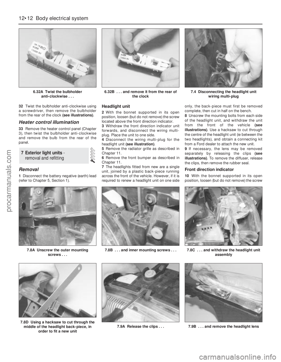
32Twist the bulbholder anti-clockwise using
a screwdriver, then remove the bulbholder
from the rear of the clock (see illustrations).
Heater control illumination
33Remove the heater control panel (Chapter
3), then twist the bulbholder anti-clockwise
and remove the bulb from the rear of the
panel.
Removal
1Disconnect the battery negative (earth) lead
(refer to Chapter 5, Section 1).
Headlight unit
2With the bonnet supported in its open
position, loosen (but do not remove) the screw
located above the front direction indicator.
3Withdraw the front direction indicator unit
forwards, and disconnect the wiring multi-
plug. Place the unit to one side.
4Disconnect the wiring multi-plug for the
headlight unit (see illustration).
5Remove the radiator grille as described in
Chapter 11.
6Remove the front bumper as described in
Chapter 11.
7The headlights fitted from new are a single
unit, joined by a plastic back-piece running
across the front of the vehicle. However, if it is
required to renew a headlight unit on one sideonly, the back-piece must first be removed
complete, then cut in half on the bench.
8Unscrew the mounting bolts from each side
of the headlight unit, and withdraw the unit
from the front of the vehicle (see
illustrations). Use a hacksaw to cut through
the centre of the headlight unit (ie between the
two headlights), and obtain a connecting kit
from a Ford dealer to attach the new unit.
9If necessary, the lens may be removed
separately by releasing the clips (see
illustrations). To remove the diffuser, release
the clips, then remove the rubber seal.
Front direction indicator
10With the bonnet supported in its open
position, loosen (but do not remove) the screw
7 Exterior light units -
removal and refitting
12•12 Body electrical system
6.32A Twist the bulbholder
anti-clockwise . . .6.32B . . . and remove it from the rear of
the clock7.4 Disconnecting the headlight unit
wiring multi-plug
7.8D Using a hacksaw to cut through the
middle of the headlight back-piece, in
order to fit a new unit7.9A Release the clips . . .7.9B . . . and remove the headlight lens
7.8A Unscrew the outer mounting
screws . . .7.8B . . . and inner mounting screws . . .7.8C . . . and withdraw the headlight unit
assembly
procarmanuals.com
Page 222 of 279
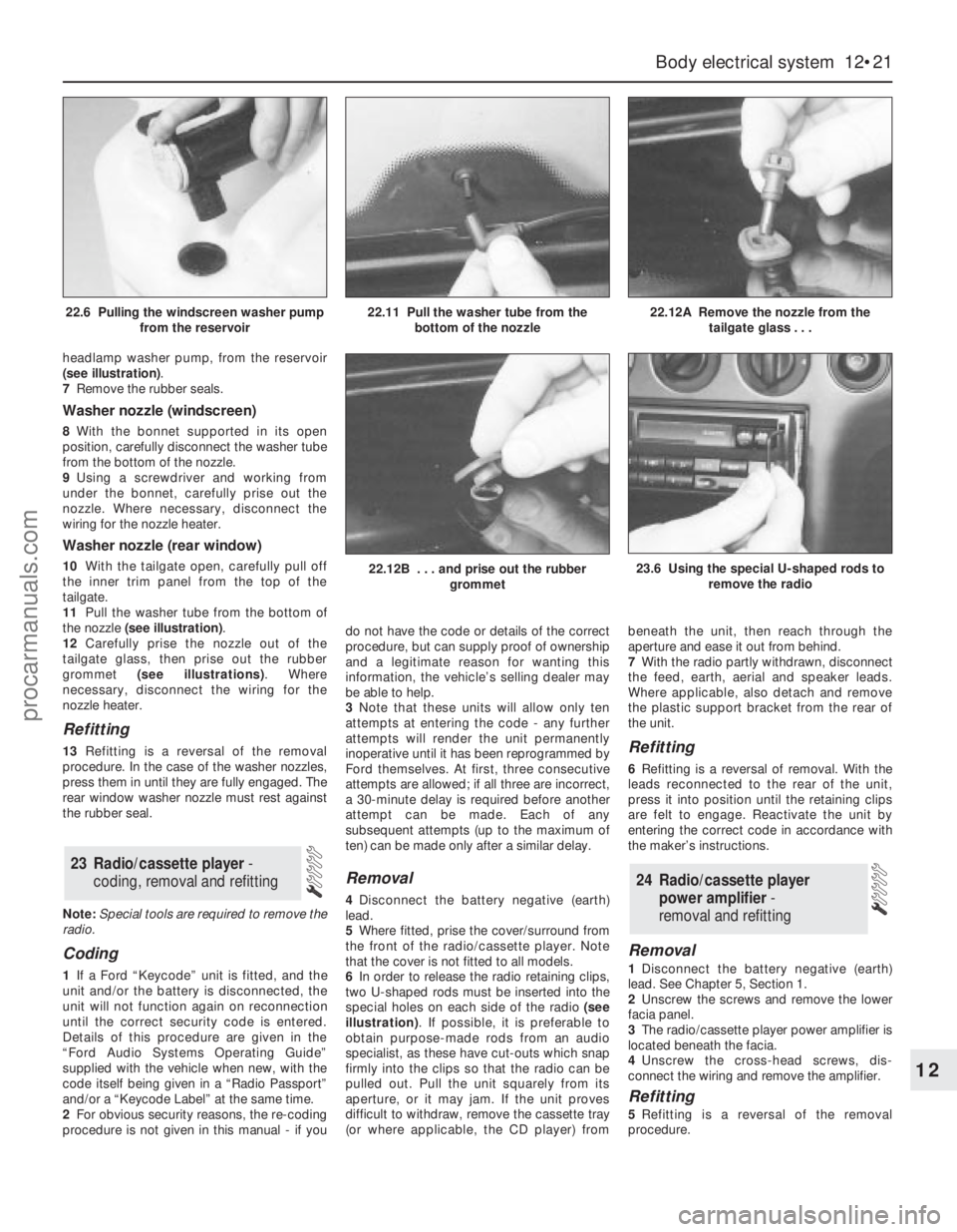
headlamp washer pump, from the reservoir
(see illustration).
7Remove the rubber seals.
Washer nozzle (windscreen)
8With the bonnet supported in its open
position, carefully disconnect the washer tube
from the bottom of the nozzle.
9Using a screwdriver and working from
under the bonnet, carefully prise out the
nozzle. Where necessary, disconnect the
wiring for the nozzle heater.
Washer nozzle (rear window)
10With the tailgate open, carefully pull off
the inner trim panel from the top of the
tailgate.
11Pull the washer tube from the bottom of
the nozzle (see illustration).
12Carefully prise the nozzle out of the
tailgate glass, then prise out the rubber
grommet (see illustrations). Where
necessary, disconnect the wiring for the
nozzle heater.
Refitting
13Refitting is a reversal of the removal
procedure. In the case of the washer nozzles,
press them in until they are fully engaged. The
rear window washer nozzle must rest against
the rubber seal.
Note:Special tools are required to remove the
radio.
Coding
1If a Ford “Keycode” unit is fitted, and the
unit and/or the battery is disconnected, the
unit will not function again on reconnection
until the correct security code is entered.
Details of this procedure are given in the
“Ford Audio Systems Operating Guide”
supplied with the vehicle when new, with the
code itself being given in a “Radio Passport”
and/or a “Keycode Label” at the same time.
2For obvious security reasons, the re-coding
procedure is not given in this manual - if youdo not have the code or details of the correct
procedure, but can supply proof of ownership
and a legitimate reason for wanting this
information, the vehicle’s selling dealer may
be able to help.
3Note that these units will allow only ten
attempts at entering the code - any further
attempts will render the unit permanently
inoperative until it has been reprogrammed by
Ford themselves. At first, three consecutive
attempts are allowed; if all three are incorrect,
a 30-minute delay is required before another
attempt can be made. Each of any
subsequent attempts (up to the maximum of
ten) can be made only after a similar delay.
Removal
4Disconnect the battery negative (earth)
lead.
5Where fitted, prise the cover/surround from
the front of the radio/cassette player. Note
that the cover is not fitted to all models.
6In order to release the radio retaining clips,
two U-shaped rods must be inserted into the
special holes on each side of the radio (see
illustration). If possible, it is preferable to
obtain purpose-made rods from an audio
specialist, as these have cut-outs which snap
firmly into the clips so that the radio can be
pulled out. Pull the unit squarely from its
aperture, or it may jam. If the unit proves
difficult to withdraw, remove the cassette tray
(or where applicable, the CD player) frombeneath the unit, then reach through the
aperture and ease it out from behind.
7With the radio partly withdrawn, disconnect
the feed, earth, aerial and speaker leads.
Where applicable, also detach and remove
the plastic support bracket from the rear of
the unit.
Refitting
6Refitting is a reversal of removal. With the
leads reconnected to the rear of the unit,
press it into position until the retaining clips
are felt to engage. Reactivate the unit by
entering the correct code in accordance with
the maker’s instructions.
Removal
1Disconnect the battery negative (earth)
lead. See Chapter 5, Section 1.
2Unscrew the screws and remove the lower
facia panel.
3The radio/cassette player power amplifier is
located beneath the facia.
4Unscrew the cross-head screws, dis-
connect the wiring and remove the amplifier.
Refitting
5Refitting is a reversal of the removal
procedure.
24 Radio/cassette player
power amplifier -
removal and refitting
23 Radio/cassette player -
coding, removal and refitting
Body electrical system 12•21
12
22.12B . . . and prise out the rubber
grommet23.6 Using the special U-shaped rods to
remove the radio
22.6 Pulling the windscreen washer pump
from the reservoir22.11 Pull the washer tube from the
bottom of the nozzle22.12A Remove the nozzle from the
tailgate glass . . .
procarmanuals.com
Page 244 of 279
Wiring diagrams 12•43
12
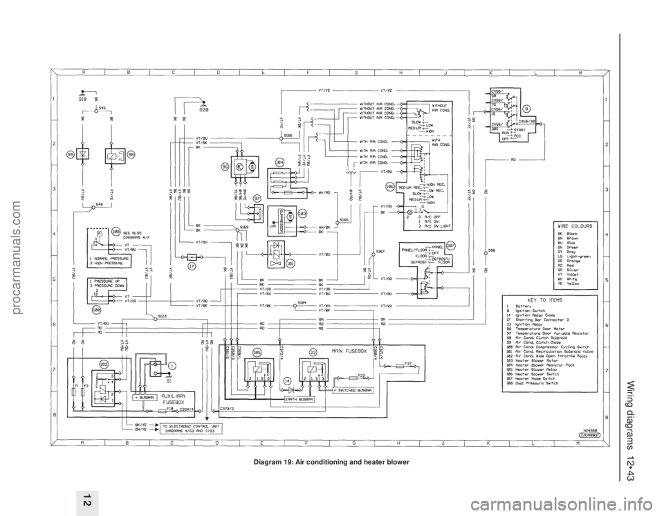
Diagram 19: Air conditioning and heater blower
procarmanuals.com
Page 267 of 279
Engine misfires throughout the driving speed range
m mFuel filter choked (Chapter 1).
m mFuel pump faulty or delivery pressure low (Chapter 4).
m mFuel tank vent blocked or fuel pipes restricted (Chapter 4).
m mVacuum leak at the inlet manifold or associated hoses (Chap-
ters 1, 4 and 6).
m mWorn, faulty or incorrectly-gapped spark plugs (Chapter 1).
m mFaulty spark plug HT leads (Chapter 1).
m mFaulty ignition coil (Chapter 5).
m mEngine management system fault (Chapters 1, 4, 5 and 6)
m mUneven or low cylinder compressions (Chapter 2, Part A).
Engine hesitates on acceleration
m
mWorn, faulty or incorrectly-gapped spark plugs (Chapter 1).
m mEngine management system fault (Chapters 1, 4, 5 and 6).
m mVacuum leak at the inlet manifold or associated hoses (Chap-
ters 1, 4 and 6).
Engine stalls
m mIdle speed control valve faulty (Chapter 4).
m mEngine management system fault (Chapters 1, 4, 5 and 6).
m mVacuum leak at the inlet manifold or associated hoses (Chap-
ters 1, 4 and 6).
m mFuel filter choked (Chapter 1).
m mFuel pump faulty or delivery pressure low (Chapter 4).
m mFuel tank vent blocked or fuel pipes restricted (Chapter 4).
Engine lacks power
m
mIncorrect ignition timing (Chapters 5 and 6).
m mEngine management system fault (Chapters 1, 4, 5 and 6).
m mTiming belt incorrectly fitted or incorrectly tensioned (Chapter 2,
Part A).
m mFuel filter choked (Chapter 1).
m mFuel pump faulty or delivery pressure low (Chapter 4).
m mUneven or low cylinder compressions (Chapter 2, Part A).
m mWorn, faulty or incorrectly-gapped spark plugs (Chapter 1).
m mVacuum leak at the inlet manifold or associated hoses (Chap-
ters 1, 4 and 6).
m mBrakes binding (Chapters 1 and 9).
m mClutch slipping (Chapter 8).
m mAutomatic transmission fluid level incorrect (Chapter 1).
Engine runs-on after switching off
m
mIdle speed excessively high (Chapters 4 and 6).
m mEngine management system fault (Chapters 1, 4, 5 and 6).
m mExcessive carbon build-up in engine (Chapter 2, Part A).
m mHigh engine operating temperature (Chapter 3).
Engine backfires
m
mIgnition timing incorrect (Chapters 5 and 6).
m mEngine management system fault (Chapters 1, 4, 5 and 6).
m mTiming belt incorrectly fitted or incorrectly tensioned (Chapter 2,
Part A).
m mVacuum leak at the inlet manifold or associated hoses (Chap-
ters 1, 4 and 6).
Oil pressure warning light illuminated with engine
running
m mLow oil level or incorrect oil grade (Chapter 1).
m mFaulty oil pressure warning light switch (Chapter 2, Part A).
m mWorn engine bearings and/or oil pump (Chapter 2).
m mHigh engine operating temperature (Chapter 3).
m mOil pressure relief valve defective (Chapter 2, Part A).
m mOil pick-up strainer clogged (Chapter 2, Part A).
Engine noises
Pre-ignition (pinking) or knocking during acceleration or under
load
m mIgnition timing incorrect (Chapters 5 and 6).
m mIncorrect grade of fuel (Chapter 4).
m mVacuum leak at the inlet manifold or associated hoses (Chap-
ters 1, 4 and 6).
m mExcessive carbon build-up in engine (Chapter 2, Part A).
Whistling or wheezing noises
m mLeaking inlet manifold gasket (Chapter 2, Part A).
m mLeaking exhaust manifold gasket or downpipe-to-manifold joint
(Chapters 1, 2 Part A, and 4).
m mLeaking vacuum hose (Chapters 1, 4, 6 and 9).
m mBlowing cylinder head gasket (Chapter 2, Part A).
Tapping or rattling noises
m mFaulty hydraulic tappet(s) (Chapter 2, Part A).
m mWorn valve gear or camshaft (Chapter 2, Part A).
m mWorn timing belt or tensioner (Chapter 2, Part A).
m mAncillary component fault (water pump, alternator, etc) (Chap-
ters 3 and 5).
Knocking or thumping noises
m mWorn big-end bearings (regular heavy knocking, perhaps less
under load) (Chapter 2, Part B).
m mWorn main bearings (rumbling and knocking, perhaps worsening
under load) (Chapter 2, Part B).
m mPiston slap (most noticeable when cold) (Chapter 2, Part B).
m mAncillary component fault (water pump, alternator, etc) (Chap-
ters 3 and 5).
REF•8Fault Finding
2 Cooling system
Overheating
m mInsufficient coolant in system (Chapter 1).
m mThermostat faulty (Chapter 3).
m mRadiator core blocked or grille restricted (Chapter 3).
m mRadiator electric cooling fan(s) or coolant temperature sensor faulty
(Chapter 3).
m mEngine management system fault (Chapters 1, 4, 5 and 6).
m mPressure cap faulty (Chapter 3).
m mAuxiliary drivebelt worn or slipping (Chapter 1).
m mIgnition timing incorrect (Chapters 5 and 6).
m mInaccurate coolant temperature gauge sender (Chapter 3).
m mAir-lock in cooling system (Chapter 1).
Overcooling
m
mThermostat faulty (Chapter 3).
m mInaccurate coolant temperature gauge sender (Chapter 3).
External coolant leakage
m
mDeteriorated or damaged hoses or hose clips (Chapter 1).
m mRadiator core or heater matrix leaking (Chapter 3).
m mPressure cap faulty (Chapter 3).
m mWater pump seal leaking (Chapter 3).
m mBoiling due to overheating (Chapter 3).
m mCore plug leaking (Chapter 2, Part B).
procarmanuals.com
Page 277 of 279
REF•18Index
E
Earth fault - 12•4
Economy/Sport mode switch - 12•7
ECU (Electronic Control Unit) - 6•10, 6•11,
6•12
EGR exhaust gas pressure differential
sensor - 6•16
EGR system - 6•15, 6•16
Electric shock - 0•5
Electric windows fault - REF•12
Electrical system - 0•8, 1•11, 1•20
Electrical system fault - REF•12
Electrically-operated windows - 12•7
Electrolyte - 1•8
Electronic control system - 4•9, 6•2
Emblems - 11•17
Emission checks - 0•10
Emissions control systems - 6•1
Engine compartment light - 12•11
Engine electrical systems- 5•1et seq
Engine fault finding - REF•7, REF•8, REF•10
Engine management system - 4•8, 4•9
Engine oil - 1•2, 1•6, 1•16
Engine oil level sensor - 12•18
Engine removal and general engine
overhaul procedures- 2B•1et seq
Environmental considerations - REF•4
Evaporative emissions control (EVAP)
system - 6•14
Evaporator - 3•9
Exhaust gas pressure differential sensor -
6•11, 6•12, 6•13
Exhaust Gas Recirculation (EGR) system -
6•15, 6•16
Exhaust manifold - 2A•8
Exhaust system - 0•9, 0•10, 1•18, 4•12,
REF•9
Expansion tank - 3•5, 3•6
FFacia - 11•21, 11•23
Fan(s) - 3•4, 12•11
Fault code read-out - 6•6
Fault finding- REF•6et seq
Fault finding - automatic transmission -
7B•1
Fault finding - electrical system - 12•4
Filling - 11•3
Fire - 0•5
Fluid level checks - 1•6
Flywheel - 2A•24
Foglight - 12•7, 12•9, 12•13
Foglight warning indicator - 12•11
Fuel and exhaust systems- 0•10, 4•1et
seq
Fuel and exhaust system fault finding -
REF•9
Fuel consumption high - REF•9
Fuel cut-off switch - 4•8
Fuel filter - 1•26
Fuel gauge - 4•6
Fuel gauge fault - REF•12
Fuel hoses - 1•15
Fuel injection system - 4•8, 4•9
Fuel injectors - 4•10
Fuel lines - 1•19, 4•2
Fuel odour - REF•9Fuel pressure check - 4•5
Fuel pressure regulator - 4•11
Fuel pump - 4•5, 4•6
Fuel rail - 4•10
Fuel system - 4•2
Fuel tank - 4•7, 4•8
Fume or gas intoxication - 0•5
Fumes from exhaust system - REF•9
Fuses - 12•5
G
Gaiters - 1•18, 8•7, 8•9, 10•21
Gashes in bodywork - 11•3
Gaskets - REF•4
Gear lever - 7A•2
Gear selection problems - REF•9, REF•10
Gearbox oil - 1•2
Gearchange linkage - 7A•2
Gearchange selector shaft - 7A•3
Glossary of technical terms - REF•13
Glovebox - 11•22
Glovebox light - 12•11
Grab handle - 11•20
H
Handbrake - 0•7, 9•16, 12•7
Handles - 11•10, 11•11, 11•12, 11•13,
12•11
Hazard flashers - 12•7, 12•11
HC emissions - 0•10
Headlight - 1•8, 12•7, 12•8, 12•12, 12•13
Heated rear window - 12•8
Heated seat - 12•8
Heated windscreen - 12•8
Heater - 3•2, 3•7, 3•8, 12•11, 12•12
Horn - 12•7, 12•15
Horn fault - REF•12
Hoses - 1•14, 3•2, 9•11
HT leads - 1•24
Hub and bearings - 10•5, 10•9, 10•14
Hydraulic fluid - 1•2
Hydraulic pipes and hoses - 9•11
Hydraulic system - 9•12
Hydraulic tappets - 2A•14
Hydrofluoric acid - 0•5
I
Idle speed - 4•9, 4•11, 6•10
Idle-increase solenoid valve - 4•12
Ignition coil - 5•3
Ignition module - 5•4
Ignition switch - 12•6
Ignition system - 5•3
Ignition timing - 5•4, 6•10
In-car engine repair procedures- 2A•1et
seq
Indicators - 12•7, 12•9, 12•12
Information sensors - 6•10
Inlet manifold - 2A•7
Instrument panel - 12•7, 12•11, 12•14
Instruments - 1•20
Instruments fault - REF•12
Intake air temperature sensor - 6•11, 6•13
Introduction to the Ford Mondeo - 0•4
J
Jacking - 0•11
Joint mating faces - REF•4
Jump starting - 0•12
K
Knuckle - 10•5, 10•10, 10•14
L
Leaks - 0•13, 1•14, REF•9
Light units - 12•12
Lights - 12•7, 12•11
Lights inoperative - REF•12
Locknuts, locktabs and washers - REF•4
Locks - 11•6, 11•10, 11•12, 11•13, 11•15,
11•16, 11•17, 12•6, REF•12
Low air temperature warning sender unit -
12•18
Low coolant warning switch - 12•18
Low washer fluid switch - 12•18
Lower suspension arm - 10•8, 10•9, 10•13,
10•16
Lubrication system - 2A•4
Luggage compartment switch - 12•7
M
Main bearings - 2B•18, 2B•20
Maintenance- Also see Routine
maintenance
Maintenance - bodywork and underframe -
11•2
Maintenance - upholstery and carpets -
11•3
Manifolds - 2A•7, 2A•8
Manual transmission- 1•17, 2A•24, 2B•3,
2B•4, 7A•1et seq
Manual transmission fault finding - REF•9
Manual transmission oil - 1•2
Master cylinder - 9•10
Mirrors - 0•7, 11•14, 12•7
Misfire - REF•7, REF•8
Mixture - 0•10, 4•9
MOT test checks- 0•7et seq
Mountings - 2A•24, 7A•7, 7B•5
N
Number plate light - 12•10, 12•13
O
Oil (transmission) - 1•2
Oil (engine) - 1•2, 1•6, 1•16
Oil cooler - 2A•22
Oil level sensor - 2A•22, 12•18
Oil pressure warning light illuminated -
REF•8
procarmanuals.com