1993 DODGE TRUCK wheel bolts
[x] Cancel search: wheel boltsPage 1006 of 1502
1
.
NW4500
MANUAL
TRANSMISSION 21 - 5 making transmission removal/installation easier.
Cylinder does not have to be removed completely. (28) Remove bolts attaching transmission to clutch
housing.
(29) Move transmission rearward until drive pin
ion clears clutch disc and release bearing. (30) Lower transmission and remove it from under
vehicle.
(31) If transmission will be overhauled, thoroughly
clean transmission exterior with solvent or steam
gun.
TRANSMISSION INSTALLATION-4-WHEEL DRIVE (1) Apply light coat of Mopar high temperature
bearing grease to contact surfaces of following com
ponents: • drive gear splines and pilot bearing hub • release bearing slide surface of front retainer
• pilot bearing
• release bearing bore
• release fork
• release fork ball stud
• propeller shaft slip yoke (2) Fill transmission with recommended lubricant.
Correct level is to bottom edge of fill plug hole. (3) Mount transmission on jack and position trans
mission under vehicle. Secure transmission to jack
with safety chains. (4) Raise transmission until drive gear is centered
in release bearing and clutch disc hub. (5) Move transmission forward and start drive gear
in release bearing and clutch disc. (6) Work transmission forward until seated against
clutch housing. Do not allow transmission to remain
unsupported after drive gear has entered clutch disc. (7) Install and tighten transmission-to-clutch hous
ing bolts to 108 N*m (80 ft. lbs.) torque. (8) Connect speed sensor and backup light switch
wires.
(9) Position transmission harness wires in clips on
shift cover. (10) Tighten slave cylinder attaching nuts and in
stall slave cylinder shield, if equipped.
(11) Install transmission mount on transmission or
rear crossmember. (12) Install rear crossmember.
(13) Remove transmission jack and engine support
fixture.
(14) Install transfer case on transmission jack. Se
cure transfer case to jack with safety chains. (15) Install new gasket on transmission adapter, or
coat adapter sealing surface with Mopar Gasket
Maker, or silicone adhesive sealer.
(16) Raise jack and align transfer case input gear
with transmission mainshaft.
(17) Move transfer case forward and seat it on
adapter.
(18) Install and tighten transfer case attaching
nuts to 47 N«m (35 ft. lbs.) torque.
(19) Connect transfer case shift lever to range le
ver on transfer case. (20) Align and connect propeller shafts. Tighten
U-joint clamp strap bolts to 19 N*m (170 in. lbs.)
torque.
(21) Check lubricant levels in transmission and
transfer case. Add lubricant if necessary.
(22) Install transfer case skid plate and crossmem
ber. Tighten attaching bolts/nuts to 41 N»m (30 ft. lbs.) torque.
(23) Install exhaust system components.
(24) Lower vehicle.
(25) Install transmission shift lever, boot and be
zel.
(26) Connect battery negative cable.
Page 1008 of 1502
NV4500
TRANSMISSION
OVERHAUL
21 - 7
EXTENSION
HOUSING
SPLINE
HEAD
BOLTS
(8)
J9221-84
Fig. 4 Extension/Adapter
Housing
Bolts
EXTENSION
HOUSING
GEAR
CASE
J9221-85
Fig.
5 Extension/Adapter
Housing
Removal/Installation
MAINSHAFT
RUBBER
SPLINE
SEAL
J9221-86
Fig.
6 Mainshaft
Spline
Seal
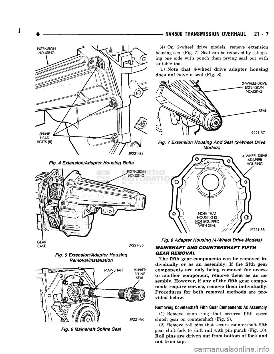
(4)
On 2-wheel drive models, remove extension
housing seal (Fig. 7). Seal can be removed by collaps ing one side with punch then prying seal out with
suitable tool.
(5) Note that 4-wheel drive adapter housing
does not have a seal (Fig. 8).
2-WHEEL-DRIVE
EXTENSION
HOUSING
SEAL
J9221-87
Fig.
7 Extension
Housing
And
Seal
(2-Wheel Drive
Models)
4-WHEEL-DRIVE
ADAPTER
HOUSING
J9221-88
Fig.
8 Adapter
Housing
(4-Wheel Drive Models)
MAINSHAFT AND COUNTERSHAFT FIFTH GEAR REMOWAL The fifth gear components can be removed in
dividually or as an assembly. If the fifth gear
components are only being removed for access
to another component, remove them as an as sembly. However, if any of the fifth gear compo
nents require service, remove them individually. Procedures for both removal methods are pro
vided below.
Removing
Countershaft
Fifth
Gear
Components
As
Assembly
(1) Remove snap ring that secures fifth speed
clutch gear on countershaft (Fig. 9). (2) Remove roll pins that secure countershaft fifth
gear shift fork to shift rail with pin punch (Fig. 10).
Roll pins are driven out from bottom of fork and
not from top.
Page 1044 of 1502
•
NV4500
TRANSMISSION OVERHAUL
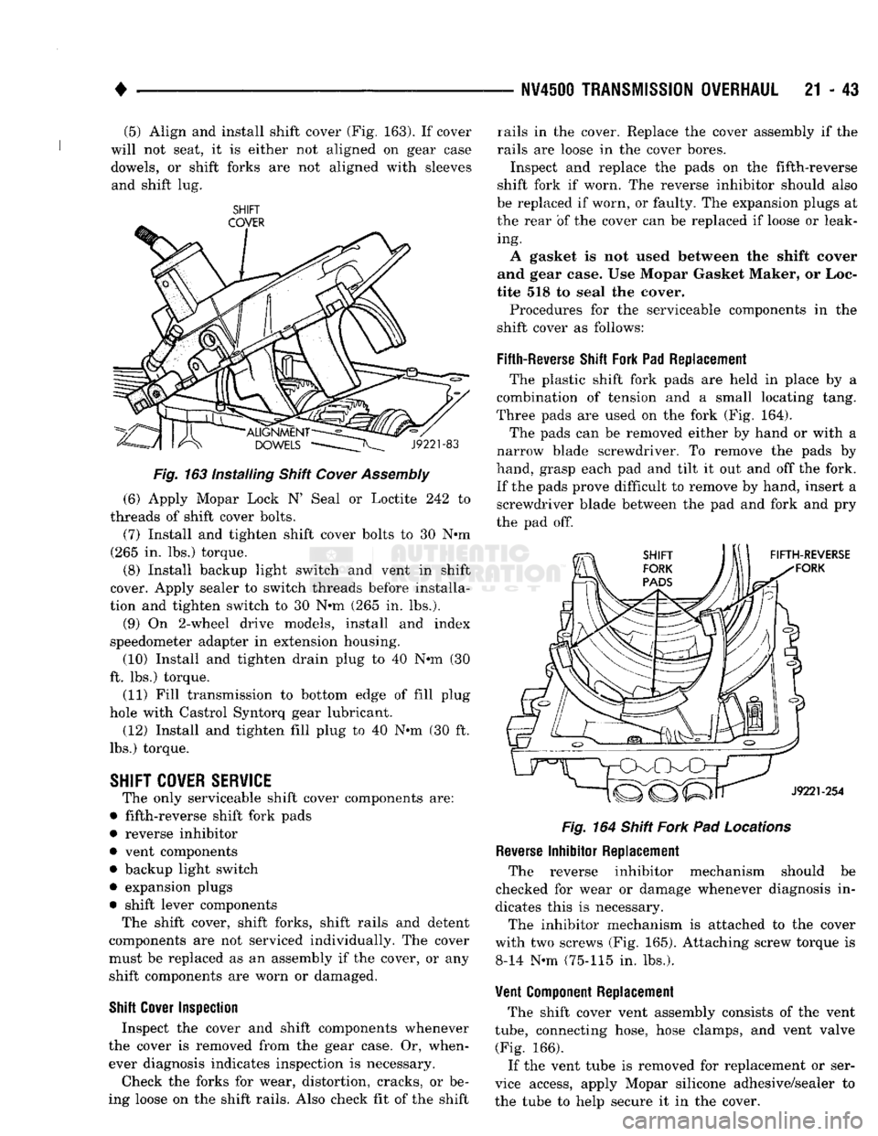
21 • 43 (5) Align and install shift cover (Fig. 163). If cover
will not seat, it is either not aligned on gear case
dowels, or shift forks are not aligned with sleeves and shift lug.
SHIFT
Fig.
163 Installing Shift
Cover
Assembly
(6) Apply Mopar Lock N' Seal or Loctite 242 to
threads of shift cover bolts. (7) Install and tighten shift cover bolts to 30 Nnn
(265 in. lbs.) torque.
(8) Install backup light switch and vent in shift
cover. Apply sealer to switch threads before installa
tion and tighten switch to 30 Nnn (265 in. lbs.).
(9) On 2-wheel drive models, install and index
speedometer adapter in extension housing. (10) Install and tighten drain plug to 40 Nnn (30
ft. lbs.) torque.
(11) Fill transmission to bottom edge of fill plug
hole with Castrol Syntorq gear lubricant.
(12) Install and tighten fill plug to 40 N-m (30 ft.
lbs.) torque.
SHIFT
COVER SERVICE
The only serviceable shift cover components are:
• fifth-reverse shift fork pads
• reverse inhibitor
• vent components • backup light switch
• expansion plugs
• shift lever components The shift cover, shift forks, shift rails and detent
components are not serviced individually. The cover
must be replaced as an assembly if the cover, or any shift components are worn or damaged.
Shift
Cover
Inspection
Inspect the cover and shift components whenever
the cover is removed from the gear case. Or, when ever diagnosis indicates inspection is necessary.
Check the forks for wear, distortion, cracks, or be
ing loose on the shift rails. Also check fit of the shift rails in the cover. Replace the cover assembly if the
rails are loose in the cover bores.
Inspect and replace the pads on the fifth-reverse
shift fork if worn. The reverse inhibitor should also
be replaced if worn, or faulty. The expansion plugs at
the rear of the cover can be replaced if loose or leak ing.
A gasket is not used between the shift cover
and gear case. Use Mopar Gasket Maker, or Loc
tite 518 to seal the cover.
Procedures for the serviceable components in the
shift cover as follows:
Fifth-Reverse
Shift
Fork Pad Replacement The plastic shift fork pads are held in place by a
combination of tension and a small locating tang.
Three pads are used on the fork (Fig. 164).
The pads can be removed either by hand or with a
narrow blade screwdriver. To remove the pads by
hand, grasp each pad and tilt it out and off the fork.
If the pads prove difficult to remove by hand, insert a screwdriver blade between the pad and fork and pry
the pad off.
Fig.
164 Shift
Fork
Pad
Locations
Reverse
Inhibitor Replacement The reverse inhibitor mechanism should be
checked for wear or damage whenever diagnosis in
dicates this is necessary.
The inhibitor mechanism is attached to the cover
with two screws (Fig. 165). Attaching screw torque is 8-14 N-m (75-115 in. lbs.).
Vent
Component
Replacement The shift cover vent assembly consists of the vent
tube,
connecting hose, hose clamps, and vent valve (Fig. 166).
If the vent tube is removed for replacement or ser
vice access, apply Mopar silicone adhesive/sealer to
the tube to help secure it in the cover.
Page 1051 of 1502
21
- 50
G360
MANUAL
TRANSMISSION
•
FRAME RAIL
CROSSMEMBER
DRIVER SIDE
BRACKET
PASSENGER.
SIDE
BRACE
CROSSMEMBER
J9221-65
Fig.
14
Crossmember
And
Braces
(17) Remove clutch slave cylinder shield (Fig. 15).
SLAVE
CYLINDER
HEAT SHIELD
J9121-269
Fig.
15 Removing/Installing
Slave
Cylinder
Shield
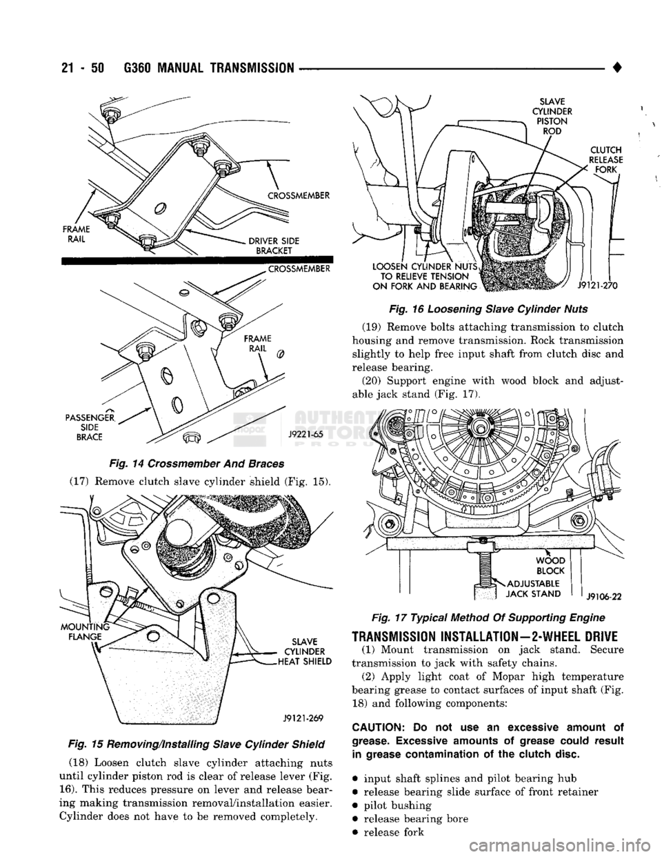
(18) Loosen clutch slave cylinder attaching nuts
until cylinder piston rod is clear of release lever (Fig.
16).
This reduces pressure on lever and release bear
ing making transmission removal/installation easier. Cylinder does not have to be removed completely.
SLAVE
CYLINDER PISTON ROD
CLUTCH
RELEASE
FORK
LOOSEN CYLINDER NUTS TO RELIEVE TENSION
ON FORK AND BEARING
J9121-270
Fig.
16
Loosening
Slave
Cylinder
Nuts
(19) Remove bolts attaching transmission to clutch
housing and remove transmission. Rock transmission slightly to help free input shaft from clutch disc and
release bearing.
(20) Support engine with wood block and adjust
able jack stand (Fig. 17).
J9106-22
Fig.
17 Typical Method Of
Supporting
Engine
TRANSMISSION
INSTALLATION—2-WHEEL
DRIVE
(1) Mount transmission on jack stand. Secure
transmission to jack with safety chains. (2) Apply light coat of Mopar high temperature
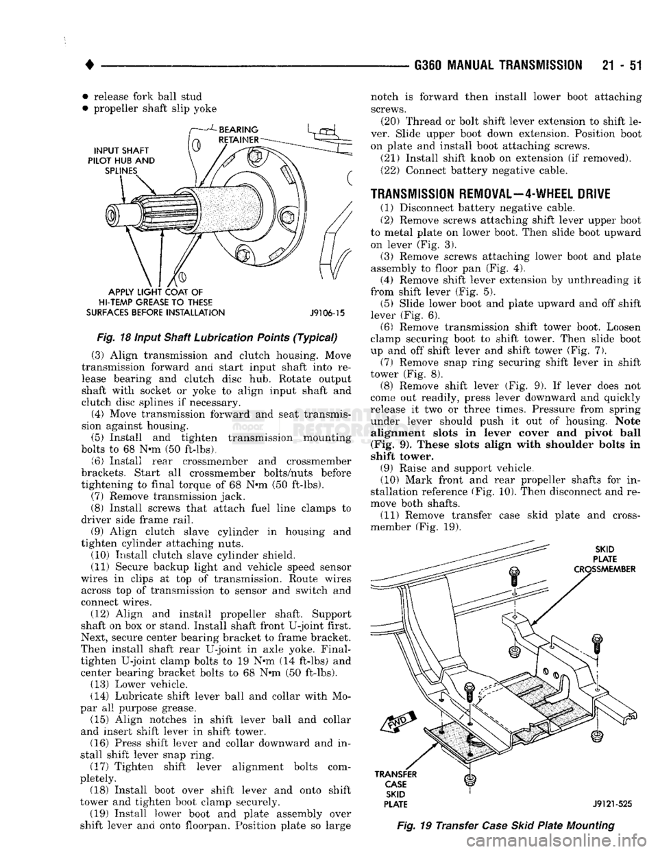
bearing grease to contact surfaces of input shaft (Fig. 18) and following components:
CAUTION:
Do not use an
excessive
amount
of
grease. Excessive
amounts
of
grease
could
result
in
grease
contamination
of the
clutch
disc.
• input shaft splines and pilot bearing hub
• release bearing slide surface of front retainer
• pilot bushing • release bearing bore
• release fork
Page 1052 of 1502
•
• release fork ball stud
• propeller shaft slip yoke
APPLY
LIGHT
COAT
OF
HI-TEMP
GREASE
TO
THESE
SURFACES
BEFORE
INSTALLATION
J9106-15
Fig.
18 input Shaft Lubrication
Points
(Typical)
(3) Align transmission and clutch housing. Move
transmission forward and start input shaft into re lease bearing and clutch disc hub. Rotate output
shaft with socket or yoke to align input shaft and
clutch disc splines if necessary.
(4) Move transmission forward and seat transmis
sion against housing. (5) Install and tighten transmission mounting
bolts to 68 N-m (50 ft-lbs). (6) Install rear crossmember and crossmember
brackets. Start all crossmember bolts/nuts before
tightening to final torque of 68 N»m (50 ft-lbs). (7) Remove transmission jack.
(8) Install screws that attach fuel line clamps to
driver side frame rail. (9) Align clutch slave cylinder in housing and
tighten cylinder attaching nuts. (10) Install clutch slave cylinder shield.
(11) Secure backup light and vehicle speed sensor
wires in clips at top of transmission. Route wires across top of transmission to sensor and switch and
connect wires.
(12) Align and install propeller shaft. Support
shaft on box or stand. Install shaft front U-joint first.
Next, secure center bearing bracket to frame bracket.
Then install shaft rear U-joint in axle yoke. Final- tighten U-joint clamp bolts to 19 N@m (14 ft-lbs) and center bearing bracket bolts to 68 N»m (50 ft-lbs). (13) Lower vehicle.
(14) Lubricate shift lever ball and collar with Mo
par all purpose grease. (15) Align notches in shift lever ball and collar
and insert shift lever in shift tower. (16) Press shift lever and collar downward and in
stall shift lever snap ring. (17) Tighten shift lever alignment bolts com
pletely. (18) Install boot over shift lever and onto shift
tower and tighten boot clamp securely. (19) Install lower boot and plate assembly over
shift lever and onto floorpan. Position plate so large G360
MANUAL TRANSMISSION
21 - 51
SKID
PLATE
J9121-525
Fig.
19 Transfer
Case
Skid
Plate
Mounting
notch is forward then install lower boot attaching
screws. (20) Thread or bolt shift lever extension to shift le
ver. Slide upper boot down extension. Position boot on plate and install boot attaching screws.
(21) Install shift knob on extension (if removed). (22) Connect battery negative cable.
TRANSMISSION REMOVAL—4-WHEEL DRIVE
(1) Disconnect battery negative cable.
(2) Remove screws attaching shift lever upper boot
to metal plate on lower boot. Then slide boot upward on lever (Fig. 3).
(3) Remove screws attaching lower boot and plate
assembly to floor pan (Fig. 4). (4) Remove shift lever extension by unthreading it
from shift lever (Fig. 5). (5) Slide lower boot and plate upward and off shift
lever (Fig. 6). (6) Remove transmission shift tower boot. Loosen
clamp securing boot to shift tower. Then slide boot
up and off shift lever and shift tower (Fig. 7).
(7)
Remove snap ring securing shift lever in shift
tower (Fig. 8). (8) Remove shift lever (Fig. 9). If lever does not
come out readily, press lever downward and quickly
release it two or three times. Pressure from spring under lever should push it out of housing. Note alignment slots in lever cover and pivot ball
(Fig. 9). These slots align with shoulder bolts in
shift tower.
(9) Raise and support vehicle.
(10) Mark front and rear propeller shafts for in
stallation reference (Fig. 10). Then disconnect and re
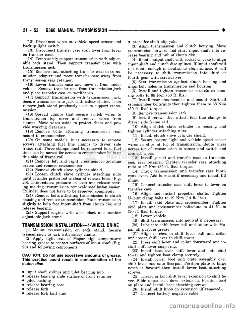
move both shafts. (11) Remove transfer case skid plate and cross-
member (Fig. 19).
Page 1053 of 1502
21 - 52 G360
MANUAL
TRANSMISSION
• (12) Disconnect wires at vehicle speed sensor and
backup light switch.
(13) Disconnect transfer case shift lever from lever
on transfer case.
(14) Temporarily support transmission with adjust
able jack stand. Then support transfer case with
transmission jack.
(15) Remove nuts attaching transfer case to trans
mission adapter and move transfer case away from
transmission rear retainer.
(16) Lower transfer case and move it from under
vehicle. Remove transfer case from transmission jack and place transfer case on workbench.
(17) Support transmission with transmission jack.
Secure transmission to jack with safety chains. Then
remove jack stand previously used to support trans
mission.
(18) Spread clamps that secure switch wires to
transmission top cover and remove wires from clamps. Move wires aside to protect them and pro
vide working clearance.
(19) Remove bolts attaching transmission rear
mount to crossmember.
(20) On some models, it is necessary to remove
screws attaching fuel line clamps to driver side
frame rail. Three clamps must be removed to so fuel lines can be moved for access to crossmember bolts at
this side of frame rail.
(21) Remove left and right crossmember-to-frame
braces and remove crossmember.
(22) Remove clutch slave cylinder shield.
(23) Loosen clutch slave cylinder attaching nuts
until cylinder piston rod is clear of release lever (Fig.
20).
This reduces pressure on lever and release bear
ing making transmission removal/installation easier. Cylinder does not have to be removed completely.
(24) Remove bolts attaching transmission to clutch
housing and remove transmission. Rock transmission slightly to help free input shaft from clutch disc and
release bearing.
(25) Support engine with wood block and another
adjustable jack stand.
TRANSMISSION
INSTALLATION—4-WHEEL
DRIVE
(1) Mount transmission on jack stand. Secure
transmission to jack with safety chains.
(2) Apply light coat of Mopar high temperature
bearing grease to contact surfaces of input shaft (Fig. 20) and following components:
CAUTION:
Do not use
excessive
amounts
of
grease.
This
practice
could
result in contamination of the
clutch
disc.
• input shaft splines and pilot bearing hub
• release bearing slide surface of front retainer
• pilot bushing
• release bearing bore
• release fork
• release fork ball stud • propeller shaft slip yoke
(3) Align transmission and clutch housing. Move
transmission forward and start input shaft into re lease bearing and hub of clutch disc. (4) Rotate output shaft with socket or yoke to align
input shaft and clutch disc splines. If input shaft will
not rotate enough in neutral to align splines, it will
be necessary to shift transmission into third or fourth gear with screwdriver. (5) Seat transmission against clutch housing and
align bolt holes in transmission and housing. (6) Install and tighten transmission-to-clutch hous
ing bolts to 68 N-m (50 ft. lbs.). (7) Install rear crossmember and mount. Start all
crossmember bolts/nuts then tighten them to 68 N*m (50 ft. lbs.) torque. (8) Remove transmission jack.
(9) Install screws that attach fuel line clamps to
driver side frame rail. (10) Align clutch slave cylinder in housing and
tighten cylinder attaching nuts. (11) Install clutch slave cylinder shield.
(12) Secure backup light and vehicle speed sensor
wires in clips at top of transmission. Route wires across top of transmission to sensor and switch and
connect wires.
(13) Install gasket and transfer case on transmis
sion rear retainer. Tighten transfer case attaching
nuts to 47 N-m (35 ft. lbs.) torque. (14) Check transmission and transfer case lubri
cant levels. Add lubricant if necessary and install fill
plugs.
(15) Connect transfer case shift lever to lever on
transfer case.
(16) Align and install propeller shafts. Tighten
U-joint clamp bolts to 19 N-m (14 ft. lbs.). (17) Install skid plate and crossmember. Tighten
skid plate and crossmember bolts/nuts to 41 N—m
(30 ft. lbs.) torque.
(18) Lower vehicle.
(19) Shift transmission into neutral if necessary.
(20) Lubricate shift lever ball and collar with Mo
par all purpose grease. (21) Align notches in shift lever ball and collar
and insert shift lever in shift tower. (22) Press shift lever and collar downward and in
stall shift lever snap ring. (23) Install boot over shift lever and onto shift
tower and tighten boot clamp securely. (24) Install lower boot and plate assembly over
shift lever and onto floorpan. Position plate so large
notch is forward then install lower boot attaching screws. (25) Thread or bolt shift lever extension to shift le
ver. Slide upper boot down extension. Position boot on plate and install boot attaching screws. (26) Install shift knob on extension (if removed).
(27) Connect battery negative cable.
Page 1054 of 1502
•
G360
TRANSMISSION OVERHAUL
21 - 53
G360
TRANSMISSION
OVERHAUL
INDEX
page
Transmission
Assembly
and
Adjustment
.......
63
Transmission
Cleaning
and
Inspection
59
TRANSMISSION
DISASSEMBLY
SHIFT COVER REMOVAL (1) Shift transmission into neutral.
(2) Remove shift cover bolts.
(3) Loosen shift cover with
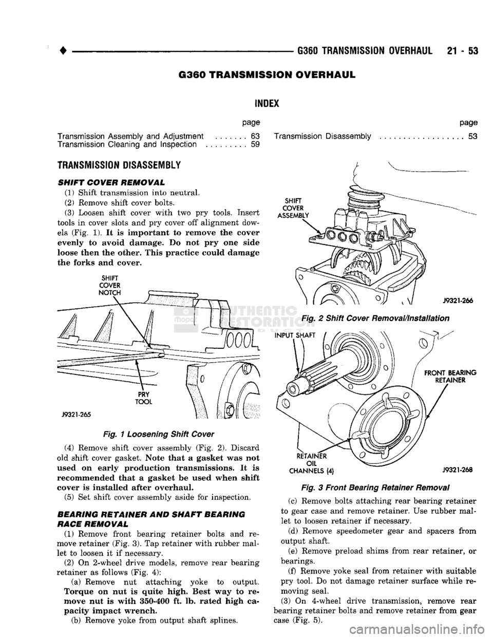
two pry
tools. Insert
tools
in
cover slots
and pry
cover
off
alignment dow els
(Fig. 1). It is
important
to
remove
the
cover evenly
to
avoid damage.
Do not pry one
side
loose then
the
other. This practice could damage the forks
and
cover.
SHIFT
COVER
Fig.
1
Loosening
Shift
Cover
(4) Remove shift cover assembly
(Fig. 2).
Discard
old shift cover gasket. Note that
a
gasket
was not
used
on
early production transmissions.
It is
recommended that
a
gasket
be
used when shift
cover
is
installed after overhaul. (5)
Set
shift cover assembly aside
for
inspection.
REARING
RETAINER
AND
SHAFT BEARING
RACE
REMOVAL (1) Remove front bearing retainer bolts
and re
move retainer
(Fig. 3). Tap
retainer with rubber mal let
to
loosen
it if
necessary.
(2)
On
2-wheel drive models, remove rear bearing
retainer
as
follows
(Fig. 4):
(a) Remove
nut
attaching yoke
to
output.
Torque
on nut is
quite high. Best
way to re
move
nut is
with 350-400
ft. lb.
rated high
ca
pacity impact wrench.
(b) Remove yoke from output shaft splines.
page
Transmission
Disassembly
53
Fig.
2
Shift
Cover
Removal/Installation
CHANNELS
(4)
J9321-268
Fig.
3
Front Bearing Retainer
Removal
(c) Remove bolts attaching rear bearing retainer
to gear case
and
remove retainer.
Use
rubber mal let
to
loosen retainer
if
necessary.
(d) Remove speedometer gear
and
spacers from
output shaft.
(e) Remove preload shims from rear retainer,
or
bearings.
(f) Remove yoke seal from retainer with suitable
pry tool.
Do not
damage retainer surface while
re
moving seal.
(3)
On
4-wheel drive transmission, remove rear
bearing retainer bolts
and
remove retainer from gear case
(Fig. 5).
Page 1072 of 1502
•
G360
TRANSMISSION OVERHAUL
21 - 71
DEPTH
GAUGE
REAR
RETAINER COUNTERSHAFT
BEARING SHIM
BORE
J9321-332
Fig.
68
Measuring
Depth Of Countershaft Bearing
Shim
Bore
(in Rear
Retainer)
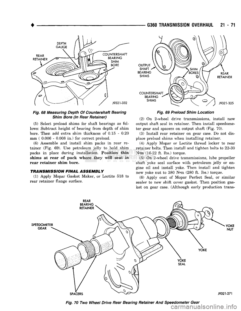
(5) Select preload shims for shaft bearings as fol
lows:
Subtract height of bearing from depth of shim
bore.
Then add extra shim thickness of 0.15 - 0.20 mm ( 0.006 - 0.008 in.) for correct preload.
(6) Assemble and install shim packs in rear re
tainer (Fig. 69). Use petroleum jelly to hold shim
packs in place during installation. Position thin shims at rear of pack where they will seat in
rear retainer shim bore.
TRANSMISSION FINAL ASSEMBLY (1) Apply Mopar Gasket Maker, or Loctite 518 to
rear retainer flange surface. OUTPUT
SHAFT
BEARING SHIMS
COUNTERSHAFT BEARING SHIMS REAR
RETAINER
J9321-325
Fig.
69 Preload
Shim
Location (2) On 2-wheel drive transmissions, install new
output shaft seal in retainer. Then install speedome
ter gear and spacers on output shaft (Fig. 70).
(3) Install rear retainer on gear case. Do not dis
place preload shims when installing retainer. (4) Apply Mopar or Loctite thread locker to rear
retainer bolts. Then install and tighten bolts to 22-30 N-m (16-22 ft. lbs.) torque.
(5) On 2-wheel drive transmissions, lube propeller
shaft yoke seal surface with petroleum jelly or en
gine oil and install yoke. Then install and tighten
new yoke nut to 380 N*m (280 ft. lbs.) torque.
(6) Apply coat of Mopar Perfect Seal, or similar
sealer to new shift cover gasket. Then position gas
ket on gear case. (Although early production trans- REAR
BEARING
RETAINER
SPEEDOMETER GEAR YOKE
NUT
YOKE
SPACERS
Fig.
70 Two
Wheel
Drive Rear Bearing Retainer And Speedometer Gear
J9321-271