1993 DODGE TRUCK wheel bolts
[x] Cancel search: wheel boltsPage 756 of 1502
5.9L
(DIESEL)
ENGINE
9-153
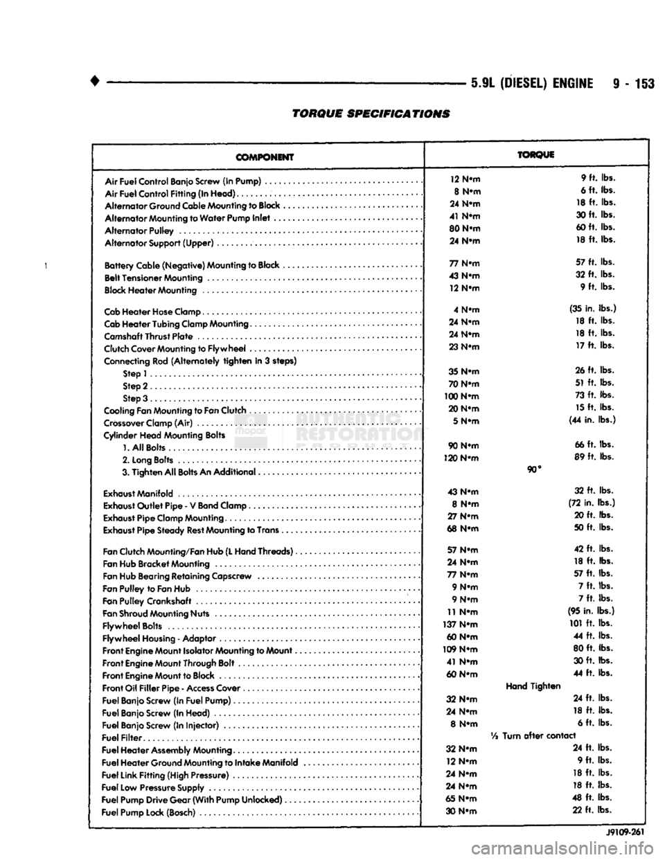
TORQUE
SPECIFICATIONS
COMPONENT
Air
Fuel
Control
Banjo Screw (In Pump) ....
Air
Fuel
Control
Fitting
(In
Head)
Alternator
Ground Cable Mounting to
Block
Alternator
Mounting to
Water
Pump
Inlet
..
Alternator
Pulley
Alternator
Support
(Upper)
Battery
Cable
(Negative)
Mounting to Block ,
Belt
Tensioner
Mounting
Block
Heater
Mounting
Cab
Heater
Hose
Clamp
Cab
Heater
Tubing
Clamp Mounting.......
Camshaft
Thrust
Plate
Clutch Cover Mounting to
Flywheel
...
Connecting Rod
(Alternately
tighten
in 3 steps) Step 1
Step 2
Step 3 .
Cooling Fan Mounting to
Fan
Clutch
Crossover
Clamp (Air)
Cylinder
Head
Mounting Bolts
1.
All
Bolts....
2.
Long
Bolts
.........
3.
Tighten
All
Bolts
An
Additional
Exhaust
Manifold
Exhaust
Outlet
Pipe
- V
Band
Clamp
Exhaust
Pipe
Clamp Mounting
Exhaust
Pipe
Steady
Rest
Mounting to Trans .
Fan
Clutch Mounting/Fan Hub
(L
Hand
Threads)..
Fan Hub
Bracket
Mounting
Fan Hub Bearing
Retaining
Capscrew
Fan
Pulley
to
Fan
Hub
Fan
Pulley
Crankshaft .
Fan
Shroud
Mounting Nuts
Flywheel
Bolts
Flywheel
Housing
- Adaptor
Front
Engine
Mount Isolator Mounting to Mount..
Front
Engine
Mount Through Bolt
Front
Engine
Mount to Block
Front
Oil
Filler
Pipe
-
Access
Cover
Fuel
Banjo Screw (In
Fuel
Pump)
Fuel
Banjo Screw (In
Head)
Fuel
Banjo Screw (In
Injector)
Fuel
Filter
Fuel
Heater
Assembly
Mounting
Fuel
Heater
Ground Mounting to
Intake
Manifold
Fuel
Link
Fitting
(High Pressure)
Fuel
Low Pressure Supply
Fuel
Pump
Drive
Gear
(With
Pump
Unlocked)
Fuel
Pump Lock (Bosch)
TORQUE
12 N-m 9 ft. lbs.
8 N-m 6 ft. lbs.
24 N-m 18 ft. lbs.
41 N*m 30 ft. lbs.
80 N-m 60 ft. lbs.
24 N-m 18 ft. lbs.
77 N-m 57 ft. lbs.
43 N-m 32 ft. lbs.
12 N-m 9 ft. lbs.
4 N-m (35 in. lbs.)
24 N-m 18 ft. lbs.
24 N-m 18 ft. lbs.
23 N-m 17 ft. lbs.
35 N-m 26 ft. lbs.
70 N-m 51 ft. lbs.
100 N-m 73 ft. lbs.
20 N-m 15 ft. lbs.
5
N-m (44 in. lbs.)
90 N-m 66 ft. lbs.
120 N-m 89 ft. lbs.
90°
43 N-m 32 ft. lbs.
8 N-m (72 in. lbs.)
27 N-m 20 ft. lbs.
68 N-m 50 ft. lbs.
57 N-m 42 ft. lbs.
24 N-m 18 ft. lbs.
77 N-m 57 ft. lbs.
9 N-m 7 ft. lbs.
9 N-m 7 ft. lbs.
11 N-m (95 in. lbs.)
137 N-m 101 ft. lbs.
60 N-m 44 ft. lbs.
109 N-m 80 ft. lbs.
41 N-m 30 ft. lbs.
60 N-m 44 ft. lbs.
Hand
Tighten
32 N-m 24 ft. lbs.
24 N-m 18 ft. lbs.
8 N-m 6 ft. lbs.
Vi
Turn
after
contact
32 N-m 24 ft. lbs.
12 N-m 9 ft. lbs.
24 N-m 18 ft. lbs.
24 N-m 18 ft. lbs.
65 N-m 48 ft. lbs.
30 N-m 22 ft. lbs.
J9109-261
Page 780 of 1502
•
EXHAUST
SYSTEM
AND
INTAKE
MANIFOLD
11 - 21
TURBOCHARGER
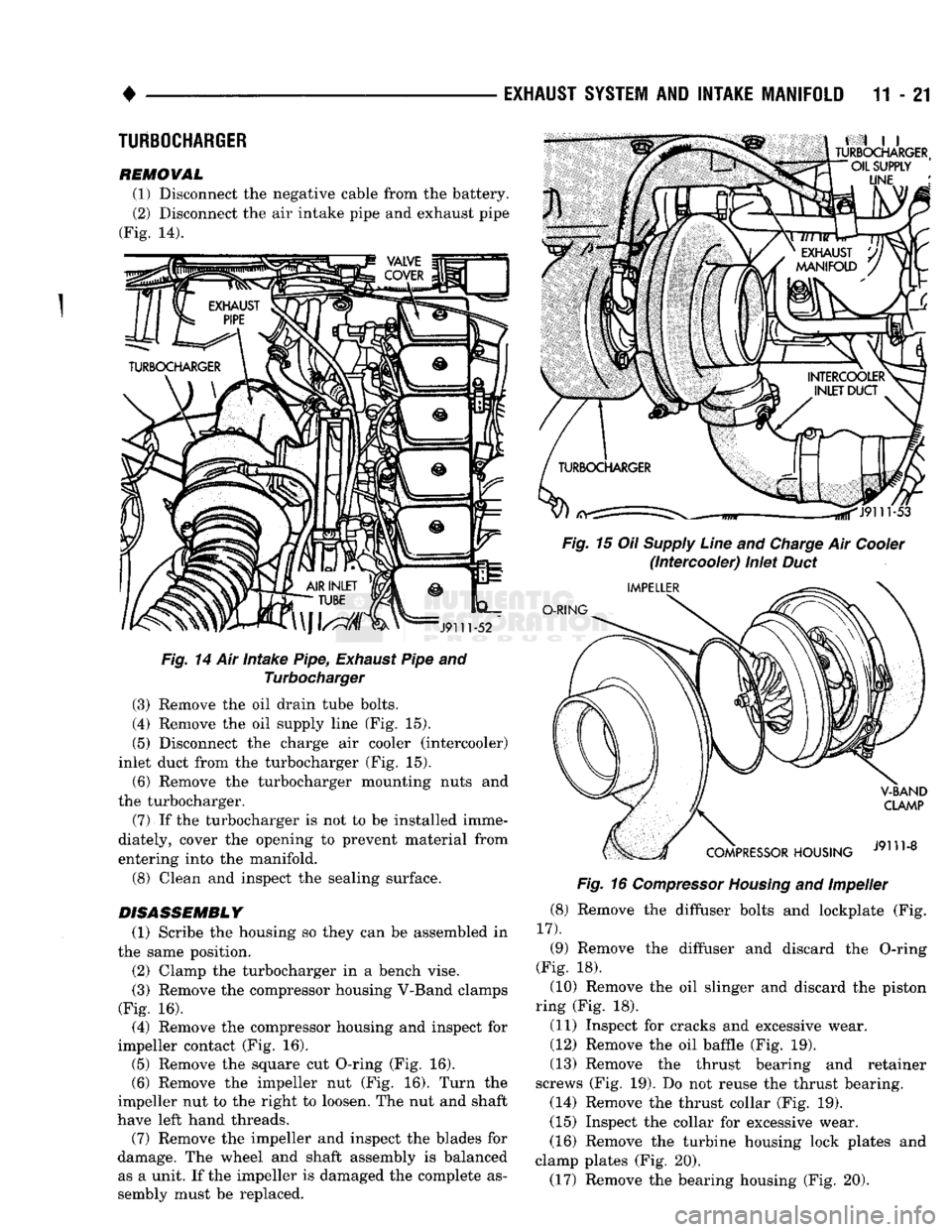
REMOVAL (1) Disconnect the negative cable from the battery. (2) Disconnect the air intake pipe and exhaust pipe
(Fig. 14).
Fig.
14 Air Intake Pipe,
Exhaust
Pipe and Turbocharger
(3) Remove the oil drain tube bolts.
(4) Remove the oil supply line (Fig. 15).
(5) Disconnect the charge air cooler (intercooler)
inlet duct from the turbocharger (Fig. 15).
(6) Remove the turbocharger mounting nuts and
the turbocharger.
(7)
If the turbocharger is not to be installed imme
diately, cover the opening to prevent material from
entering into the manifold.
(8) Clean and inspect the sealing surface.
DISASSEMBLY
(1) Scribe the housing so they can be assembled in
the same position.
(2) Clamp the turbocharger in a bench vise.
(3) Remove the compressor housing V-Band clamps
(Fig. 16). (4) Remove the compressor housing and inspect for
impeller contact (Fig. 16). (5) Remove the square cut O-ring (Fig. 16). (6) Remove the impeller nut (Fig. 16). Turn the
impeller nut to the right to loosen. The nut and shaft
have left hand threads. (7) Remove the impeller and inspect the blades for
damage. The wheel and shaft assembly is balanced as a unit. If the impeller is damaged the complete as
sembly must be replaced.
Fig.
16
Compressor
Housing
and Impeller
(8) Remove the diffuser bolts and lockplate (Fig.
17).
(9) Remove the diffuser and discard the O-ring
(Fig. 18). (10) Remove the oil slinger and discard the piston
ring (Fig. 18).
(11) Inspect for cracks and excessive wear.
(12) Remove the oil baffle (Fig. 19).
(13) Remove the thrust bearing and retainer
screws (Fig. 19). Do not reuse the thrust bearing. (14) Remove the thrust collar (Fig. 19).
(15) Inspect the collar for excessive wear.
(16) Remove the turbine housing lock plates and
clamp plates (Fig. 20). (17) Remove the bearing housing (Fig. 20).
Page 782 of 1502
•
EXHAUST
SYSTEM
AND
INTAKE MANIFOLD
11 - 23
HEAT
SHIELD
OUTER RETAINER
RINGS
BREAKING,
HOUSING
J9111-18
Fig.
24 Turbine Shaft/Heat
Shield
to Bearing
Housing
INNER
RETAINING
RINGS
INNER
RETAINING RING
J9111-14
Fig.
22
Snap Rings
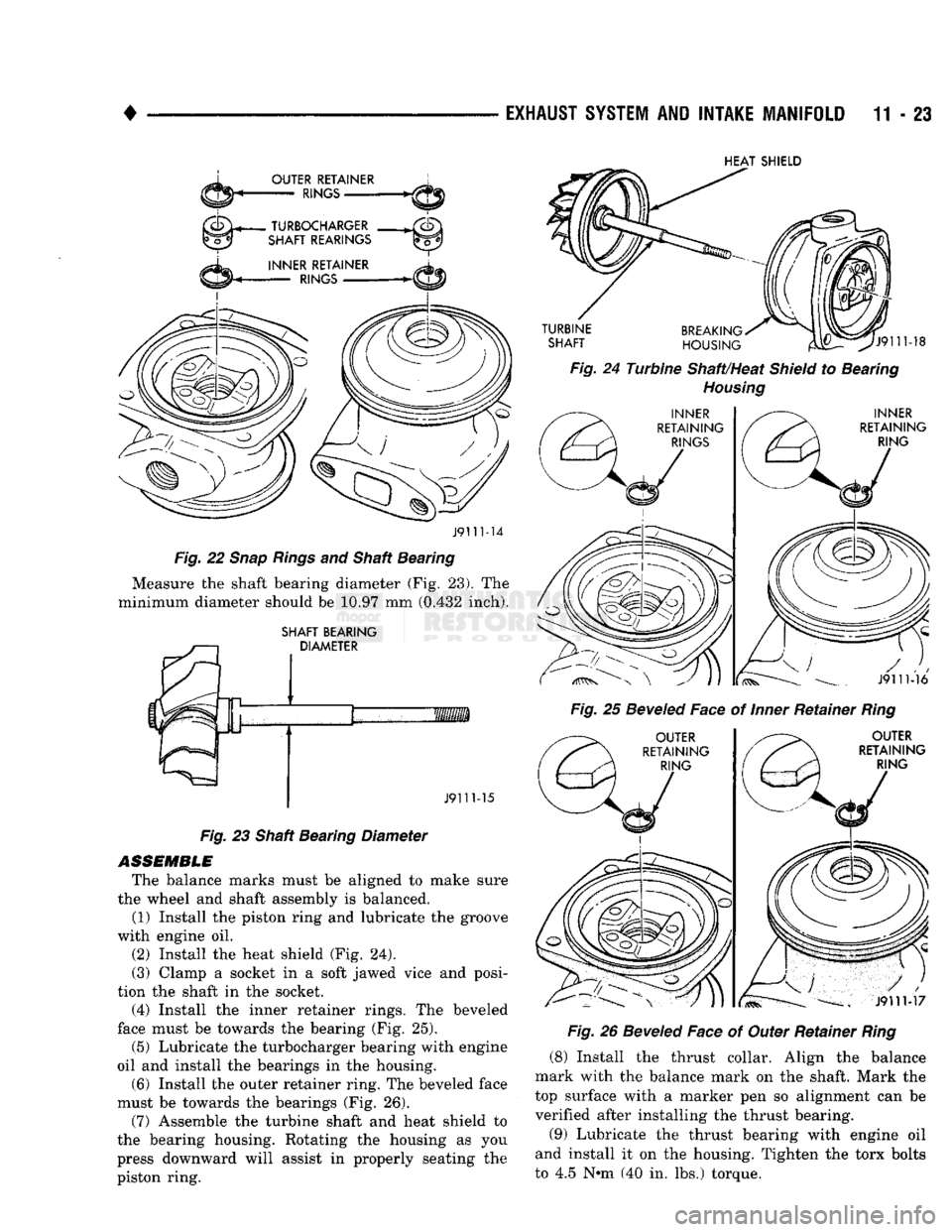
and Shaft Bearing Measure the shaft bearing diameter (Fig. 23). The
minimum diameter should be 10.97 mm (0.432 inch).
SHAFT BEARING DIAMETER Fig.
25
Beveled
Face of
Inner
Retainer
Ring
J911M6
OUTER
RETAINING RING
J9111-15
Fig.
23 Shaft Bearing Diameter
ASSEMBLE
The balance marks must be aligned to make sure
the wheel and shaft assembly is balanced. (1) Install the piston ring and lubricate the groove
with engine oil.
(2) Install the heat shield (Fig. 24).
(3) Clamp a socket in a soft jawed vice and posi
tion the shaft in the socket. (4) Install the inner retainer rings. The beveled
face must be towards the bearing (Fig. 25).
(5) Lubricate the turbocharger bearing with engine
oil and install the bearings in the housing.
(6) Install the outer retainer ring. The beveled face
must be towards the bearings (Fig. 26).
(7) Assemble the turbine shaft and heat shield to
the bearing housing. Rotating the housing as you
press downward will assist in properly seating the
piston ring.
OUTER
RETAINING RING
J9111-17
Fig.
26
Beveled
Face of Outer Retainer
Ring
(8) Install the thrust collar. Align the balance
mark with the balance mark on the shaft. Mark the
top surface with a marker pen so alignment can be verified after installing the thrust bearing.
(9) Lubricate the thrust bearing with engine oil
and install it on the housing. Tighten the torx bolts
to 4.5 N»m (40 in. lbs.) torque.
Page 784 of 1502
•
EXHAUST
SYSTEM
AND
INTAKE MANIFOLD
11 - 25
Fig.
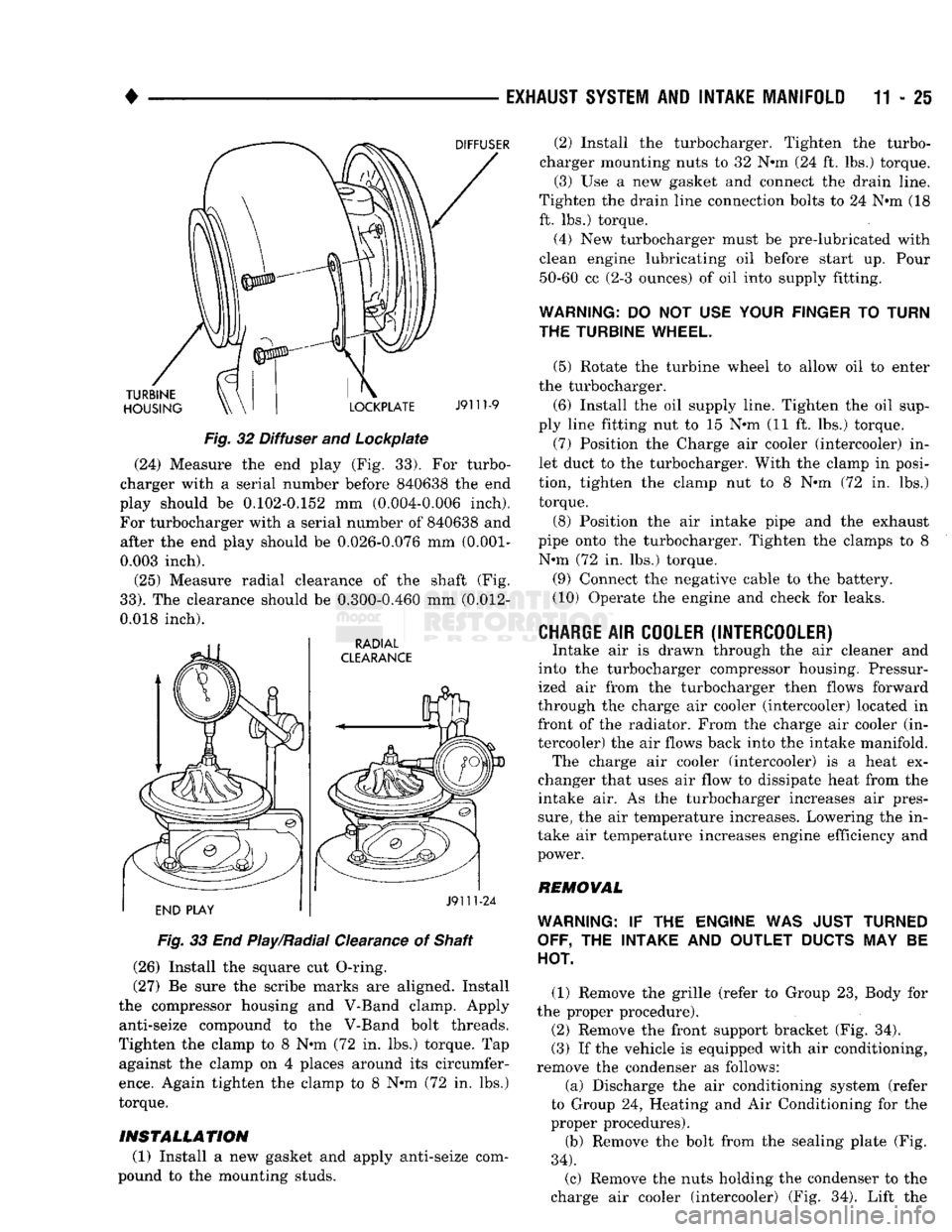
32 Diffuser and Lockpiate (24) Measure the end play (Fig. 33). For turbo
charger with a serial number before 840638 the end
play should be 0.102-0.152 mm (0.004-0.006 inch).
For turbocharger with a serial number of 840638 and after the end play should be 0.026-0.076 mm
(0.001-
0.003 inch).
(25) Measure radial clearance of the shaft (Fig.
33).
The clearance should be 0.300-0.460 mm (0.012-
0.018 inch).
Fig.
33 End Play/Radial Clearance of Shaft
(26) Install the square cut O-ring.
(27) Be sure the scribe marks are aligned. Install
the compressor housing and V-Band clamp. Apply anti-seize compound to the V-Band bolt threads.
Tighten the clamp to 8 N-m (72 in. lbs.) torque. Tap against the clamp on 4 places around its circumfer
ence.
Again tighten the clamp to 8 N-m (72 in. lbs.)
torque.
INSTALLATION
(1) Install a new gasket and apply anti-seize com
pound to the mounting studs. (2) Install the turbocharger. Tighten the turbo
charger mounting nuts to 32 N-m (24 ft. lbs.) torque. (3) Use a new gasket and connect the drain line.
Tighten the drain line connection bolts to 24 N-m (18
ft. lbs.) torque.
(4) New turbocharger must be pre-lubricated with
clean engine lubricating oil before start up. Pour 50-60 cc (2-3 ounces) of oil into supply fitting.
WARNING:
DO NOT USE
YOUR FINGER
TO
TURN
THE TURBINE WHEEL.
(5) Rotate the turbine wheel to allow oil to enter
the turbocharger.
(6) Install the oil supply line. Tighten the oil sup
ply line fitting nut to 15 N-m (11 ft. lbs.) torque. (7) Position the Charge air cooler (intercooler) in
let duct to the turbocharger. With the clamp in posi
tion, tighten the clamp nut to 8 N-m (72 in. lbs.) torque.
(8) Position the air intake pipe and the exhaust
pipe onto the turbocharger. Tighten the clamps to 8 N-m (72 in. lbs.) torque.
(9) Connect the negative cable to the battery.
(10) Operate the engine and check for leaks.
CHARGE
AIR
COOLER (INTERCOOLER)
Intake air is drawn through the air cleaner and
into the turbocharger compressor housing. Pressur
ized air from the turbocharger then flows forward
through the charge air cooler (intercooler) located in front of the radiator. From the charge air cooler (in
tercooler) the air flows back into the intake manifold. The charge air cooler (intercooler) is a heat ex
changer that uses air flow to dissipate heat from the
intake air. As the turbocharger increases air pres
sure,
the air temperature increases. Lowering the in
take air temperature increases engine efficiency and
power.
REMOVAL
WARNING:
IF THE
ENGINE
WAS
JUST TURNED OFF,
THE
INTAKE
AND
OUTLET
DUCTS
MAY BE
HOT.
(1) Remove the grille (refer to Group 23, Body for
the proper procedure).
(2) Remove the front support bracket (Fig. 34).
(3) If the vehicle is equipped with air conditioning,
remove the condenser as follows:
(a) Discharge the air conditioning system (refer
to Group 24, Heating and Air Conditioning for the
proper procedures).
(b) Remove the bolt from the sealing plate (Fig.
34).
(c) Remove the nuts holding the condenser to the
charge air cooler (intercooler) (Fig. 34). Lift the
Page 817 of 1502
13
- 30 FRAME AND BUMPERS
ATTACHED COMPONENTS
SKID
PLATES
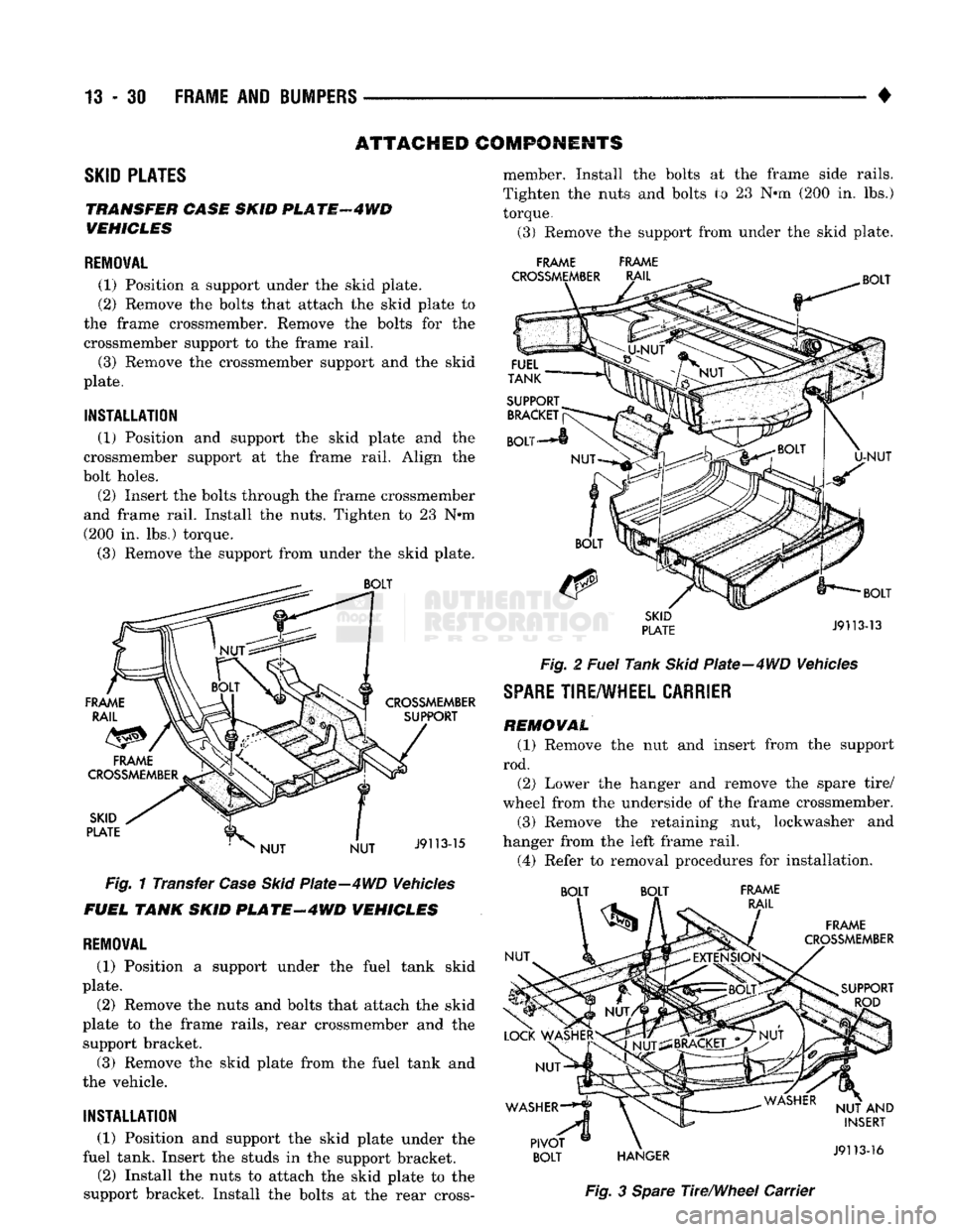
TRANSFER CASE SKID
PL
ATF
4 WD
VEHICLES
REMOVAL
(1) Position
a
support under
the
skid plate.
(2) Remove
the
bolts that attach
the
skid plate
to
the frame crossmember. Remove
the
bolts
for the
crossmember support
to the
frame rail.
(3) Remove
the
crossmember support
and the
skid
plate.
INSTALLATION
(1) Position
and
support
the
skid plate
and the
crossmember support
at the
frame rail. Align
the
bolt holes.
(2) Insert
the
bolts through
the
frame crossmember
and frame rail. Install
the
nuts. Tighten
to 23 N*m
(200
in. lbs.)
torque.
(3) Remove
the
support from under
the
skid plate.
Fig.
1
Transfer
Case Skid
Plate—4WD Vehicles
FUEL TANK SKID
PLATE-4WD
VEHICLES
REMOVAL
(1) Position
a
support under
the
fuel tank skid
plate.
(2) Remove
the
nuts
and
bolts that attach
the
skid
plate
to the
frame rails, rear crossmember
and the
support bracket.
(3) Remove
the
skid plate from
the
fuel tank
and
the vehicle.
INSTALLATION
(1) Position
and
support
the
skid plate under
the
fuel tank. Insert
the
studs
in the
support bracket.
(2) Install
the
nuts
to
attach
the
skid plate
to the
support bracket. Install
the
bolts
at the
rear cross- member. Install
the
bolts
at the
frame side rails.
Tighten
the
nuts
and
bolts
to 23 N*m (200 in. lbs.)
torque.
(3) Remove
the
support from under
the
skid plate.
FRAME FRAME
Fig.
2
Fuel
Tank
Skid
Plate-4WD Vehicles
SPARE
TIRE/WHEEL
CARRIER
REMOVAL
(1) Remove
the nut and
insert from
the
support
rod. (2) Lower
the
hanger
and
remove
the
spare tire/
wheel from
the
underside
of the
frame crossmember.
(3) Remove
the
retaining
nut,
lockwasher
and
hanger from
the
left frame rail.
(4) Refer
to
removal procedures
for
installation. BOLT BOLT FRAME
Fig.
3
Spare
The/Wheel Carrier
Page 818 of 1502
1
•
FRAME
AND
BUMPERS
13 - 31 PIVOT BOL T ADJUSTMENT
(1) Refer to the Pivot Bolt Height chart and deter
mine the length of dimension A for the pivot bolt.
PIVOT BOLT HEIGHT
PIVOT BOLT HEIGHT
RIM SIZE TIRE SIZE BOLT HEIGHT
15 x 6.5 P195/75R-15
4.0"
P205/75R-15 4.0"
P235/75R-15XL
5.0"
15
x 7.0
P235/75R-15XL 5.2"
10R-15LT-B
5.62"
16 x 6.0 7.50-16 SINGLE & DUAL
6.75"
LT215/85R-16 SINGLE
4.5"
LT215/85R-16 DUAL 5.0"
LT235/85R-16
5.0"
16.5 x 6.0 8.00-16.5 SINGLE
4.12"
8.00-16.5 DUAL
5.0"
16.5 x 6.75 8.75-16.5 5.0"
NOTE: 7.50 x 16 TIRE SHOULD BE INSTALLED IN A DISH
UP POSITION ONLY
(2) Loosen the pivot bolt nut and adjust dimension
A to required length.
INSTALLATION (1) Position the hanger under the frame side rails
and insert the pivot bolt in the frame rail hole. (2) Install the lockwasher and the nut on the pivot
bolt. Tighten the nut to 61 N*m (45 ft. lbs).
(3) Position the spare tire/wheel on the hanger.
Raise the hanger and insert the support rod in the
hole.
(4) Install the washer,nut and insert on the sup
port rod. Tighten the nut to 11 Nnn (95 in. lbs.).
CAB
REMOVAL
The cab is attached to the frame with holddowns
(Figs.
4 and 5). The cab can be removed for repair or
service. Refer to the associated component procedure
when necessary.
(1) Disconnect the battery cables from the termi
nals.
Remove the battery from the tray.
(2) Disconnect the wire harness connectors from
the engine components. Disconnect from the frame. (3) Disconnect the parking brake cable and the
brake lines. (4) Disconnect the engine controls.
(5)
Disconnect the heater and A/C hoses.
(6) Disconnect the cable from the starter motor.
(7)
Disconnect the transmission and transfer case
(if equipped) shift linkage. (8) Disconnect the tubing from the clutch master
cylinder (if equipped). (9) Disconnect the steering shaft from the steering
gear. (10) Disconnect all remaining connections between
the cab and the frame components. (11) Remove the restraint cable from the cab.
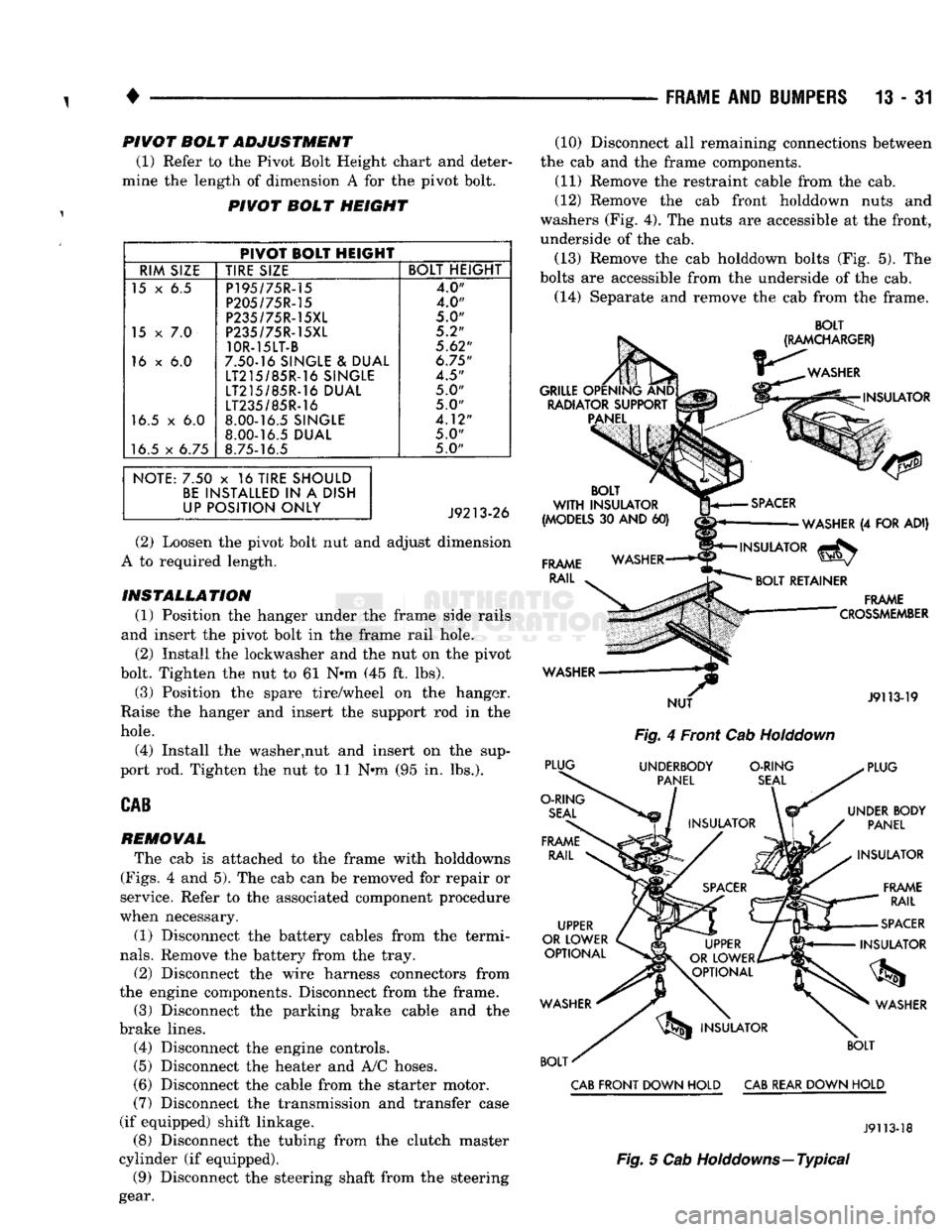
(12) Remove the cab front holddown nuts and
washers (Fig. 4). The nuts are accessible at the front,
underside of the cab.
(13) Remove the cab holddown bolts (Fig. 5). The
bolts are accessible from the underside of the cab.
(14) Separate and remove the cab from the frame.
BOLT
Fig.
4 Front Cab
Holddown
CAB
FRONT DOWN HOLD
CAB
REAR DOWN HOLD
J9113-18
Fig.
5 Cab Holddowns—Typical
Page 907 of 1502
DIESEL FUEL INJECTION—GENERAL DIAGNOSIS
INDEX
page
Air
in
Fuel System
90
Air Intake Heater
. 90
Diagnostic
Trouble Code (DTC)
. 95
DRB
II
Scan
Tool
95
Engine
Speed
Sensor
91
Fuel Heater
91
Fuel
Injection
Pump
91
Fuel Injectors
92
Fuel Supply Restrictions
92
page
Fuel/Water Separator
Filter 92
High
Pressure Fuel Line Restrictions
93
KSB
Solenoid
. 93
Mechanical
Lift
Pump
93
On-Board
Diagnostics (OBD)
94
System
Schematics—5.9L Diesel Engine
....... 95
Throttle
Position
Sensor
Test
94
Visual
Inspection
88
VISUAL
INSPECTION
A visual inspection for loose, disconnected, or incor
rectly routed wires and hoses should be made before attempting to diagnose or service the fuel injection
system. A visual check will help find these condi
tions.
It also saves unnecessary test and diagnostic
time.
A thorough visual inspection of the fuel injec
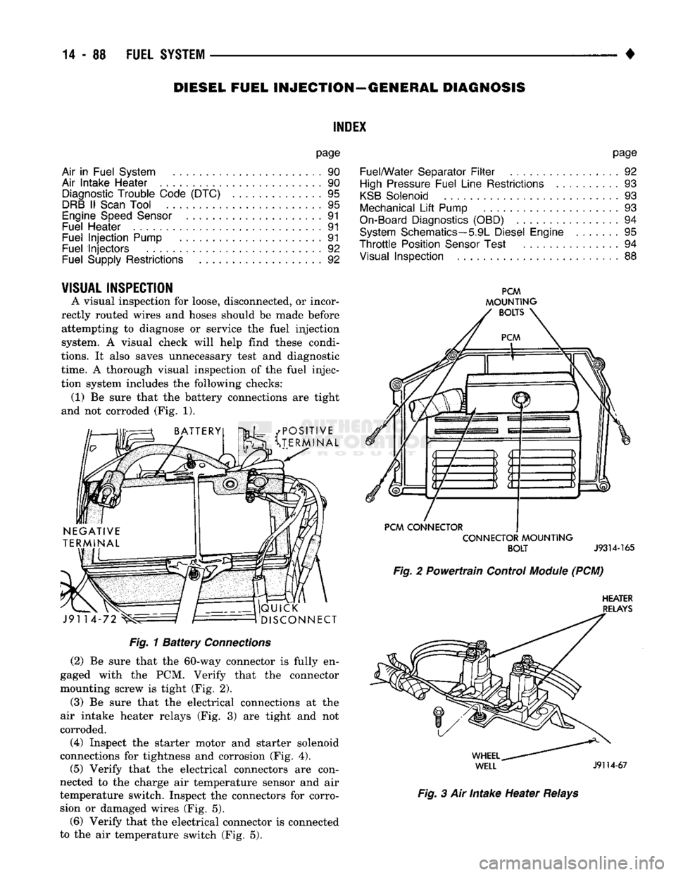
tion system includes the following checks: (1) Be sure that the battery connections are tight
and not corroded (Fig. 1).
• POSITIVE
v^3t
^TERMINAL J91 14
QUICK
DISCONNECT
PCM
MOUNTING
BOLTS
PCM
CONNECTOR CONNECTOR
MOUNTING
BOLT
J9314-165
Fig.
2 Powertrain Control
Module
(PCM)
HEATER
RELAYS
Fig.
1
Battery
Connections
(2)
Be sure that the 60-way connector is fully en
gaged with the PCM. Verify that the connector
mounting screw is tight (Fig. 2).
(3)
Be sure that the electrical connections at the
air intake heater relays (Fig. 3) are tight and not
corroded.
(4)
Inspect the starter motor and starter solenoid
connections for tightness and corrosion (Fig. 4).
(5)
Verify that the electrical connectors are con
nected to the charge air temperature sensor and air
temperature switch. Inspect the connectors for corro sion or damaged wires (Fig. 5). (6) Verify that the electrical connector is connected
to the air temperature switch (Fig. 5).
WHEEL
^
WELL
J9114-67
Fig.
3 Air Intake Heater
Relays
Page 927 of 1502
(10) Install air intake heater (with new gasket) in
reverse order of removal.
AIR
INTAKE
HE
A TER
RELA YS
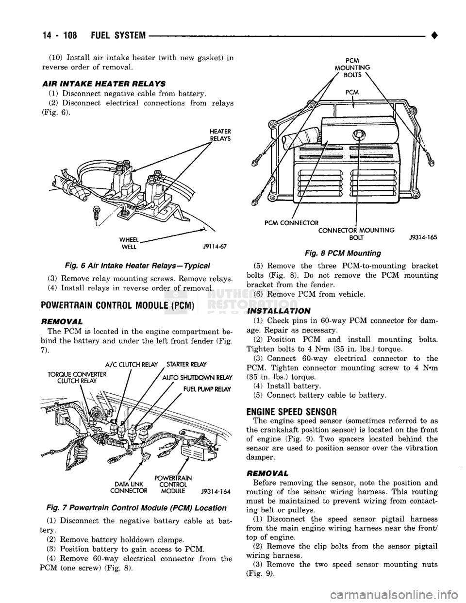
(1) Disconnect negative cable from battery.
(2) Disconnect electrical connections from relays
(Fig. 6).
HEATER
RELAYS
WHEEL..
WELL
J9114-67
Fig. 6 Air intake Heater Relays—Typical (3) Remove relay mounting screws. Remove relays.
(4) Install relays in reverse order of removal.
POWERTRAIN CONTROL MODULE
(PCI)
REMOWAL The PCM is located in the engine compartment be
hind the battery and under the left front fender (Fig.
7).
TORQUE CONVERTER
CLUTCH RELAY A/C CLUTCH RELAY STARTER RELAY
AUTO SHUTDOWN RELAY FUEL PUMP RELAY DATA LINK
CONNECTOR POWERTRAIN
CONTROL
MODULE
J9314-164
Fig. 7 Powertrain Control
Module
(PCM) Location (1) Disconnect the negative battery cable at bat
tery.
(2) Remove battery holddown clamps.
(3) Position battery to gain access to PCM,
(4) Remove 60-way electrical connector from the
PCM (one screw) (Fig. 8).
PCM
MOUNTING BOLTS
PCM CONNECTOR CONNECTOR MOUNTING
BOLT
J9314-165
Fig. 8 PCM Mounting (5) Remove the three PCM-to-mounting bracket
bolts (Fig. 8). Do not remove the PCM mounting
bracket from the fender.
(6) Remove PCM from vehicle.
INSTALLATION (1) Check pins in 60-way PCM connector for dam
age.
Repair as necessary.
(2) Position PCM and install mounting bolts.
Tighten bolts to 4 N*m (35 in. lbs.) torque.
(3) Connect 60-way electrical connector to the
PCM. Tighten connector mounting screw to 4 N#m (35 in. lbs.) torque. (4) Install battery. (5) Connect battery cable to battery.
ENGINE
SPEED SENSOR
The engine speed sensor (sometimes referred to as
the crankshaft position sensor) is located on the front of engine (Fig. 9). Two spacers located behind the
sensor are used to position sensor over the vibration
damper.
REMOWAL Before removing the sensor, note the position and
routing of the sensor wiring harness. This routing must be maintained to prevent wiring from contact
ing belt or pulleys.
(1) Disconnect the speed sensor pigtail harness
from the main engine wiring harness near the front/
top of engine.
(2) Remove the clip bolts from the sensor pigtail
wiring harness. (3) Remove the two speed sensor mounting nuts
(Fig. 9).