1993 DODGE TRUCK ignition
[x] Cancel search: ignitionPage 387 of 1502
8E
- 6
INSTRUMENT PANEL
AND
GAUGES
•
(5)
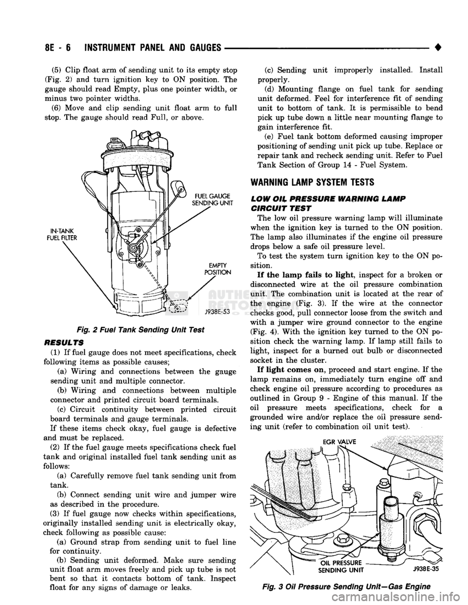
Clip float arm of sending unit to its empty stop
(Fig. 2) and turn ignition key to ON position. The
gauge should read Empty, plus one pointer width, or
minus two pointer widths.
(6) Move and clip sending unit float arm to full
stop.
The gauge should read Full, or above.
Fig. 2 Fuel Tank Sending Unit Test
RESULTS (1) If fuel gauge does not meet specifications, check
following items as possible causes; (a) Wiring and connections between the gauge
sending unit and multiple connector. (b) Wiring and connections between multiple
connector and printed circuit board terminals.
(c) Circuit continuity between printed circuit
board terminals and gauge terminals.
If these items check okay, fuel gauge is defective
and must be replaced.
(2) If the fuel gauge meets specifications check fuel
tank and original installed fuel tank sending unit as follows:
(a) Carefully remove fuel tank sending unit from
tank.
(b) Connect sending unit wire and jumper wire
as described in the procedure.
(3) If fuel gauge now checks within specifications,
originally installed sending unit is electrically okay,
check following as possible cause:
(a) Ground strap from sending unit to fuel line
for continuity. (b) Sending unit deformed. Make sure sending
unit float arm moves freely and pick up tube is not
bent so that it contacts bottom of tank. Inspect float for any signs of damage or leaks. (c) Sending unit improperly installed. Install
properly.
(d) Mounting flange on fuel tank for sending
unit deformed. Feel for interference fit of sending
unit to bottom of tank. It is permissible to bend
pick up tube down a little near mounting flange to gain interference fit.
(e) Fuel tank bottom deformed causing improper
positioning of sending unit pick up tube. Replace or
repair tank and recheck sending unit. Refer to Fuel
Tank Section of Group 14 - Fuel System.
WARNING
LAMP
SYSTEM
TESTS
LOW
OH.
PRESSURE WARNING LAMP CIRCUIT
TEST
The low oil pressure warning lamp will illuminate
when the ignition key is turned to the ON position.
The lamp also illuminates if the engine oil pressure drops below a safe oil pressure level.
To test the system turn ignition key to the ON po
sition.
If the lamp fails to light, inspect for a broken or
disconnected wire at the oil pressure combination
unit. The combination unit is located at the rear of
the engine (Fig. 3). If the wire at the connector checks good, pull connector loose from the switch and
with a jumper wire ground connector to the engine (Fig. 4). With the ignition key turned to the ON po
sition check the warning lamp. If lamp still fails to
light, inspect for a burned out bulb or disconnected
socket in the cluster.
If light comes on, proceed and start engine. If the
lamp remains on, immediately turn engine off and
check engine oil pressure according to procedures as
outlined in Group 9 - Engine of this manual. If the
oil pressure meets specifications, check for a
grounded wire and/or replace the oil pressure send
ing unit (refer to combination oil unit test). Fig. 3 Oil Pressure Sending Unit—Gas Engine
Page 388 of 1502
•
INSTRUMENT
PANEL
AND
GAUGES
8E - 7
STEERING PUMP
ENGINE
BLOCK
J9U9-74
Fig.
4 Oil
Pressure
Sending
Unit—Diesel
Engine
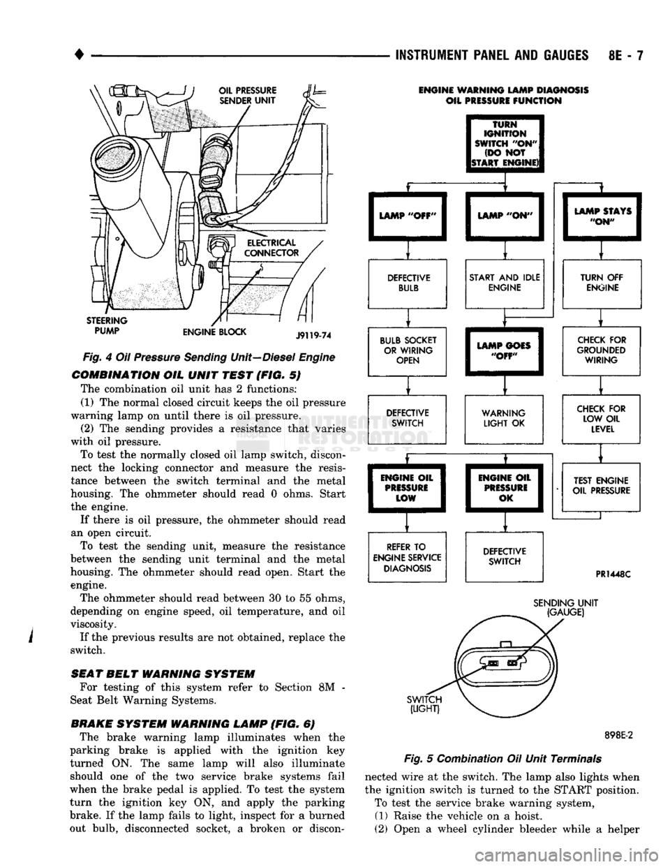
COMBINATION
OIL
UNIT
TEST
(FIG. 5)
The combination oil unit has 2 functions:
(1) The normal closed circuit keeps the oil pressure
warning lamp on until there is oil pressure. (2) The sending provides a resistance that varies
with oil pressure.
To test the normally closed oil lamp switch, discon
nect the locking connector and measure the resis
tance between the switch terminal and the metal
housing. The ohmmeter should read 0 ohms. Start
the engine.
If there is oil pressure, the ohmmeter should read
an open circuit. To test the sending unit, measure the resistance
between the sending unit terminal and the metal
housing. The ohmmeter should read open, Start the engine.
The ohmmeter should read between 30 to 55 ohms,
depending on engine speed, oil temperature, and oil
viscosity.
If the previous results are not obtained, replace the
switch.
SEAT
BELT
WARNING
SYSTEM
For testing of this system refer to Section 8M -
Seat Belt Warning Systems.
BRAKE
SYSTEM
WARNING
LAMP
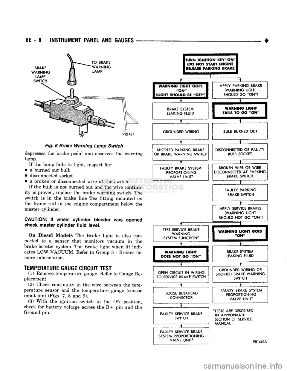
(FIG. 6) The brake warning lamp illuminates when the
parking brake is applied with the ignition key
turned ON. The same lamp will also illuminate should one of the two service brake systems fail
when the brake pedal is applied. To test the system
turn the ignition key ON, and apply the parking
brake. If the lamp fails to light, inspect for a burned
out bulb, disconnected socket, a broken or discon-
ENGINE WARNING LAMP DIAGNOSIS
OIL PRESSURE
FUNCTION
TURN
IGNITION
SWITCH
"OH"
(DO NOT
ISTART ENGINE)! LAMP "OFF'
LAMP "ON"
DEFECTIVE BULB START AND IDLE
ENGINE
BULB SOCKET OR WIRING OPEN LAMP STAYS
"ON" TURN OFF
ENGINE LAMP GOES
"OFF" DEFECTIVE
SWITCH CHECK FOR
GROUNDED WIRING
WARNING
LIGHT
OK CHECK FOR
LOW OIL LEVEL
ENGINE OIL
PRISSURi
LOW
REFER TO
ENGINE SERVICE DIAGNOSIS ENGIM
PRES
0
IE OIL
1
SURE
1
,K I
DEFECTIVE SWITCH TEST ENGINE
OIL PRESSURE
PR1448C
SWITCH
(LIGHT)
SENDING
UNIT
(GAUGE)
898E-2
Fig.
5 Combination Oil Unit Terminals
nected wire at the switch. The lamp also lights when
the ignition switch is turned to the START position. To test the service brake warning system,
(1) Raise the vehicle on a hoist.
(2) Open a wheel cylinder bleeder while a helper
Page 389 of 1502
8E
- 8 INSTRUMENT PANEL AND GAUGES
•
BRAKE
WARNING
LAMP
SWITCH TO BRAKE
WARNING LAMP
PR!
451
Fig.
6
Brake Warning
Lamp
Switch
depresses
the
brake pedal
and
observes
the
warning
lamp.
If
the
lamp fails
to
light, inspect
for:
•
a
burned
out
bulb
• disconnected socket
•
a
broken
or
disconnected wire
at the
switch. If
the
bulb
is not
burned
out and the
wire continu
ity
is
proven, replace
the
brake warning switch.
The
switch
is in the
brake line
Tee
fitting mounted
on
the frame rail
in the
engine compartment below
the
master cylinder.
CAUTION:
If
wheel cylinder bleeder
was
opened
check
master cylinder fluid level.
On Diesel Models
The
Brake light
is
also con
nected
to a
sensor that monitors vacuum
in the
brake booster system.
The
Brake light when
lit
indi cates
LOW
VACUUM. Refer
to
Group
5 -
Brakes
for
more information.
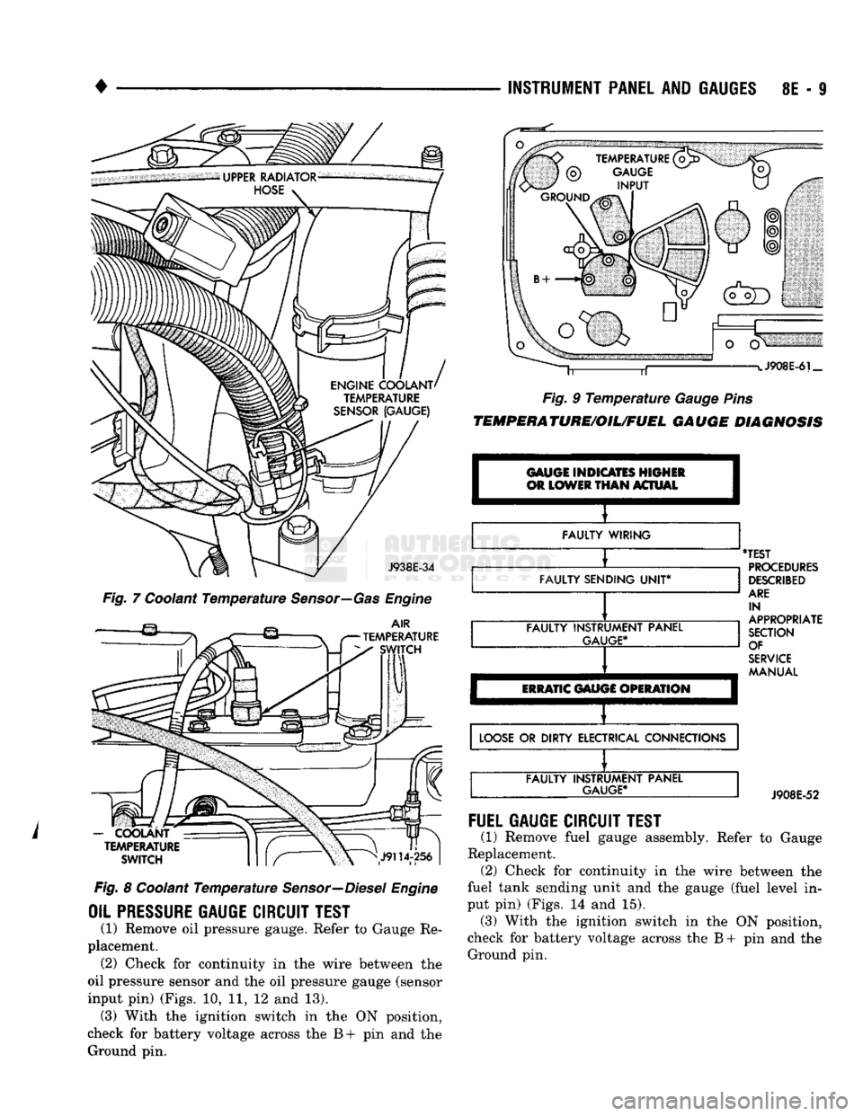
TEMPERATURE
GAUGE CIRCUIT TEST
(1) Remove temperature gauge. Refer
to
Gauge
Re
placement. (2) Check continuity
in the
wire between
the
tem
perature sensor
and the
temperature gauge (sensor
input
pin)
(Figs.
7, 8 and 9).
(3) With
the
ignition switch
in the ON
position,
check
for
battery voltage across
the B + pin and the
Ground
pin.
(TURN
IGNITION
KEY
"ON"
(DO
NOT
START
ENGINE
I
RELEASE
PARKING
BRAKE)
I
I
[
WARNING
LIGHT
GOES
I
"ON"
I
1
(LIGHT
SHOULD
BE
"OFF")!
X
APPLY PARKING BRAKE (WARNING
LIGHT
SHOULD
GO "ON")
BRAKE
SYSTEM
LEAKING FLUID
X
WARNING
LIGHT
FAILS
TO GO "ON" GROUNDED WIRING
BULB
BURNED
OUT
SHORTED PARKING BRAKE
OR BRAKE WARNING SWITCH
X
DISCONNECTED
OR
FAULTY
BULB
SOCKET
FAULTY BRAKE SYSTEM PROPORTIONING VALVE
UNIT*
BROKEN
WIRE
OR
WIRE
DISCONNECTED
AT
PARKING
BRAKE
SWITCH
X
FAULTY PARKING
BRAKE
SWITCH
X
APPLY SERVICE BRAKES
(WARNING
LIGHT
SHOULD
NOT GO "ON")
JZ
X
TEST SERVICE BRAKE WARNING
SYSTEM FUNCTION*
X
WARNING
LIGHT
GOES
"ON"
WARNING
LIGHT
DOES
NOT GO "ON"
BRAKE
SYSTEM
LEAKING FLUID
OPEN CIRCUIT
IN
WIRING
TO SERVICE BRAKE SWITCH
X
GROUNDED WIRING
OR
SHORTED BRAKE WARNING SWITCH
LOOSE
BULKHEAD CONNECTOR
X
FAULTY BRAKE SYSTEM
PROPORTIONING VALVE
UNIT*
FAULTY SERVICE BRAKE SWITCH
X
•TESTS
ARE
DESCRIBED
IN APPROPRIATE
SECTION
OF
SERVICE MANUAL
FAULTY SERVICE BRAKE
SYSTEM PROPORTIONING VALVE
UNIT*
PR1449A
Page 390 of 1502
INSTRUMENT
PANEL
AND
GAUGES
8E - S
J938E-34
Fig. 7 Coolant Temperature Sensor—Gas Engine
AIR
TEMPERATURE SWITCH
-
COOLANT TEMPERATURE
SWITCH
Fig. 8 Coolant Temperature Sensor—Diesel Engine
OIL PRESSURE
GAUGE
CIRCUIT
TEST
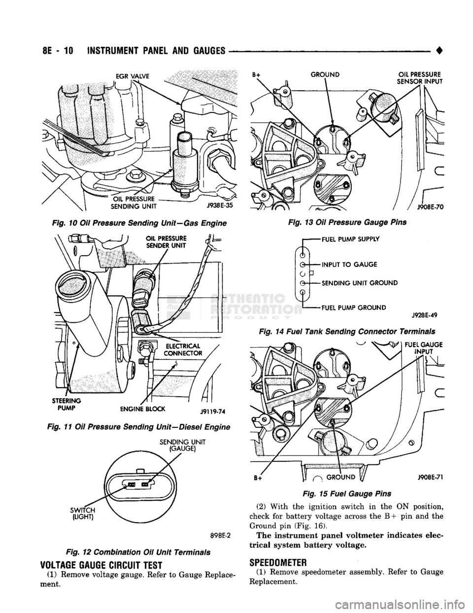
(1) Remove oil pressure gauge. Refer to Gauge Re
placement. (2) Check for continuity in the wire between the
oil pressure sensor and the oil pressure gauge (sensor
input pin) (Figs. 10, 11, 12 and 13). (3) With the ignition switch in the ON position,
check for battery voltage across the B+ pin and the Ground pin. J908E-6i_
Fig. 9 Temperature Gauge Pins
TEMPERATURE/OIL/FUEL
GAUGE
DIAGNOSIS
GAUGE INDICATES HIGHER
OR
LOWER
THAN
ACTUAL I
FAULTY WIRING
FAULTY SENDING
UNIT*
FAULTY INSTRUMENT PANEL
GAUGE*
ERRATIC
GAUGE OPERATION
'TEST
PROCEDURES
DESCRIBED
ARE
IN
APPROPRIATE
SECTION OF
SERVICE
MANUAL
LOOSE
OR DIRTY ELECTRICAL CONNECTIONS FAULTY INSTRUMENT PANEL
GAUGE*
J908E-52
FUEL
GAUGE
CIRCUIT
TEST
(1) Remove fuel gauge assembly. Refer to Gauge
Replacement. (2) Check for continuity in the wire between the
fuel tank sending unit and the gauge (fuel level in
put pin) (Figs. 14 and 15). (3) With the ignition switch in the ON position,
check for battery voltage across the B + pin and the Ground pin.
Page 391 of 1502
8E
- 10
INSTRUMENT
PANEL
AND
GAUGES
GROUND
OIL
PRESSURE
SENSOR
INPUT
J908E-70
Fig.
10 Oil Pressure
Sending
Unit—Gas Engine
STEERING
PUMP
ENGINE
BLOCK
J9119-74
Fig.
11 Oil Pressure
Sending
Unit—Diesel Engine
SENDING
UNIT
(GAUGE)
SWITCH
(LIGHT)
898E-2
Fig.
12 Combination Oil Unit Terminals
VOLTAGE
GAUGE
CIRCUIT
TEST
(1) Remove voltage gauge. Refer to Gauge Replace
ment.
Fig.
13 Oil Pressure
Gauge
Pins
r— FUEL
PUMP
SUPPLY
0 INPUT TO
GAUGE
-SENDING
UNIT
GROUND
-FUEL
PUMP
GROUND
J928E-49
Fig.
14 Fuel Tank
Sending
Connector Terminals
FUEL
GAUGE
INPUT
^
GROUND
y
J908E-71
Fig.
15 Fuel
Gauge
Pins
(2) With the ignition switch in the ON position,
check for battery voltage across the B+ pin and the Ground pin (Fig. 16).
The instrument panel voltmeter indicates elec
trical system battery voltage.
SPEEDOMETER
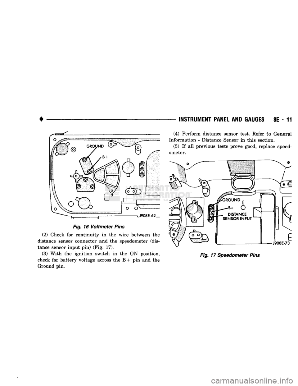
(1) Remove speedometer assembly. Refer to Gauge
Replacement.
Page 392 of 1502
•
Fig.
16
Voltmeter
Pins
(2) Check for continuity in the wire between the
distance sensor connector and the speedometer (dis
tance sensor input pin) (Fig. 17).
(3) With the ignition switch in the ON position,
check for battery voltage across the B + pin and the Ground pin. —
INSTRUMENT PANEL
AND
GAUGES
8E - 11
Fig.
17 Speedometer
Pins
(4) Perform distance sensor test. Refer to General
Information - Distance Sensor in this section.
(5)
If all previous tests prove good, replace speed
ometer.
Page 404 of 1502
AUDIO SYSTEMS
CONTENTS
SERVICE
PROCEDURES
page
.. 7
TEST PROCEDURES
page
.. 2
GENERAL
INFORMATION
For operation of the factory installed radios, refer
to the Owner Manual supplied with the vehicle. When connecting or disconnecting the Ignition Off
Draw (IOD) connector, it is important that the igni
tion switch be in the OFF position. Failure to place the ignition switch in the OFF po
sition can cause the radio display to become scram
bled when the IOD is disconnected. Connecting the IOD will correct the scrambled display.
INTERFERENCE
ELIMINATION
Many components are used on vehicles equipped
with a radio to suppress radio frequency interference (static). A capacitor is mounted inside the generator and
ground straps are utilized from cab to box and from
the engine to cowl. The previously mentioned Capacitor and Ground
Straps should be securely mounted to a clean ground
surface to work effectively. Radio resistance spark plug wires complete the in
terference suppression system. Faulty or deteriorated spark plug wires should be replaced.
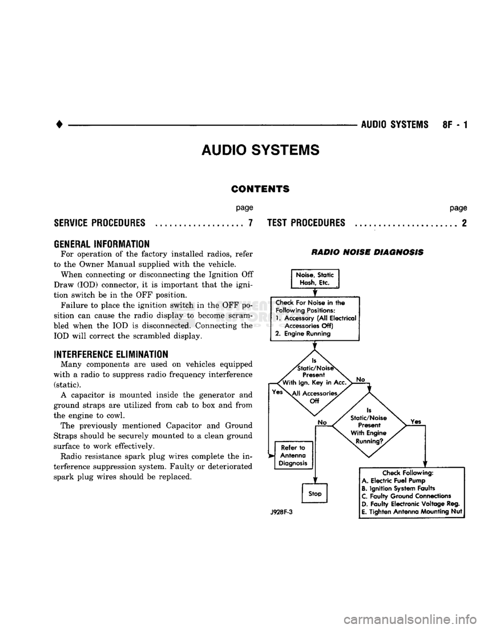
RADIO NOISE DIAGNOSIS
Noise,
Static
Hash,
Etc.
Check
For Noise in
the
Following
Positions:
1.
Accessory (All Electrical
Accessories
Off)
2. Engine Running
Is
'Static/NoiseS
Present
'With
Ign.
Key in Acc.
Yes\^|j
Accessories/
Off
No
Refer
to
Antenna
Diagnosis
f
Stop
No
Is
Static/Noise Present
With Engine
Running?.
Yes
J928F-3
Check
Following:
A.
Electric
Fuel
Pump
B.
Ignition
System
Faults
C.
Faulty Ground Connections
D.
Faulty Electronic Voltage Reg.
E.
Tighten Antenna Mounting Nut
Page 416 of 1502
•
VEHICLE SPEED CONTROL SYSTEM
8H - 1
VEHICLE SPEED CONTROL SYSTEM
CONTENTS
SERVICE
PROCEDURES
page
. 11
TEST PROCEDURES
page
.. 7
GENERAL
INFORMATION
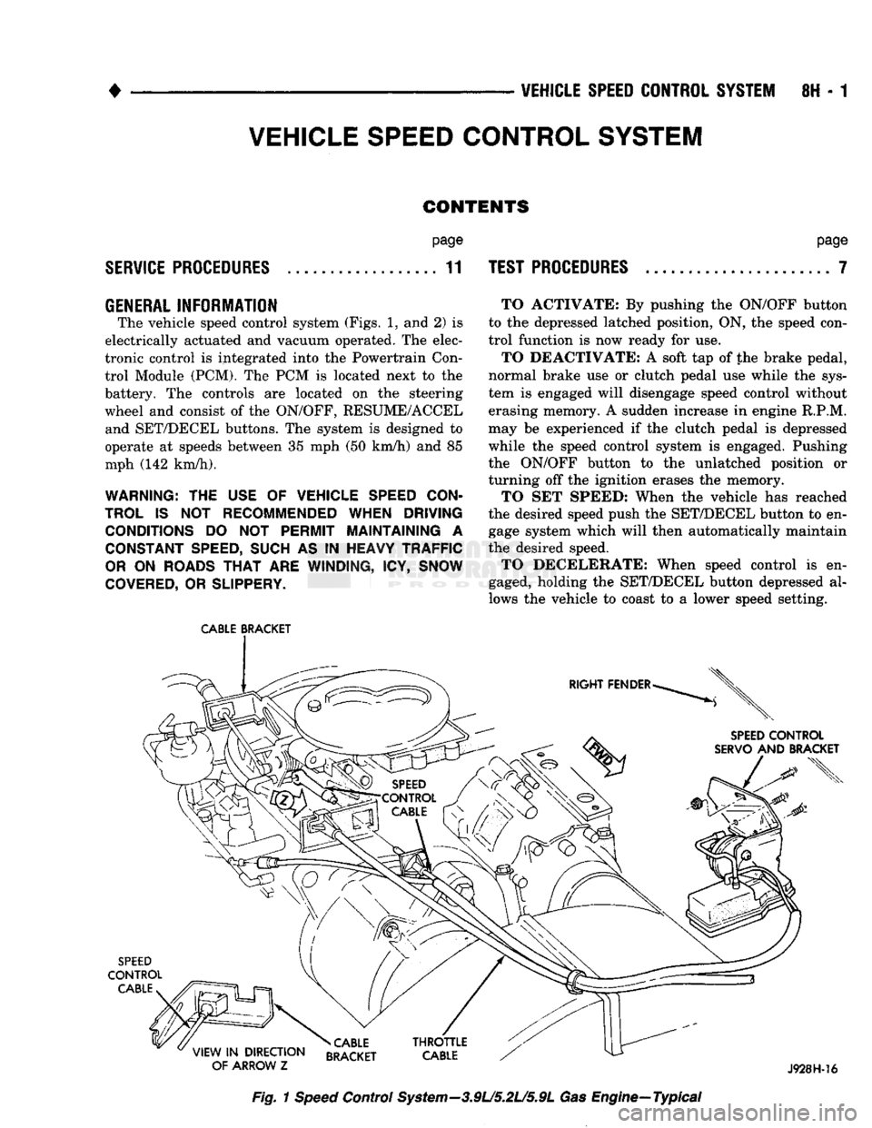
The vehicle speed control system (Figs. 1, and 2) is
electrically actuated and vacuum operated. The elec
tronic control is integrated into the Powertrain Con trol Module (PCM). The PCM is located next to the
battery. The controls are located on the steering
wheel and consist of the ON/OFF, RESUME/ACCEL and SET/DECEL buttons. The system is designed to
operate at speeds between 35 mph (50 km/h) and 85
mph (142 km/h).
WARNING: THE USE OF VEHICLE SPEED CON
TROL IS NOT RECOMMENDED WHEN DRIVING CONDITIONS DO NOT PERMIT MAINTAINING A CONSTANT SPEED, SUCH AS IN HEAVY TRAFFIC
OR ON ROADS THAT ARE WINDING, ICY, SNOW
COVERED, OR SLIPPERY.
CABLE
BRACKET
TO ACTIVATE: By pushing the ON/OFF button
to the depressed latched position, ON, the speed con
trol function is now ready for use.
TO DEACTIVATE: A soft tap of the brake pedal,
normal brake use or clutch pedal use while the sys
tem is engaged will disengage speed control without
erasing memory. A sudden increase in engine R.P.M.
may be experienced if the clutch pedal is depressed
while the speed control system is engaged. Pushing
the ON/OFF button to the unlatched position or
turning off the ignition erases the memory.
TO SET SPEED: When the vehicle has reached
the desired speed push the SET/DECEL button to en gage system which will then automatically maintain
the desired speed. TO DECELERATE: When speed control is en
gaged, holding the SET/DECEL button depressed al
lows the vehicle to coast to a lower speed setting.
SPEED
CONTROL
SERVO
AND BRACKET
SPEED
CONTROL
CABLE
»CABLE
VIEW
IN
DIRECTION RRAfKFT
OF ARROW
Z BRACKET J928H-16
Fig.
1
Speed
Control System—3.9L/5.2L/5.9L Gas Engine—Typical