1993 DODGE TRUCK ignition
[x] Cancel search: ignitionPage 422 of 1502
•
VEHICLE
SPEED
CONTROL SYSTEM
8H - 7
TEST
PROCEDURES
INDEX
page
Checking
for
Diagnostic
Trouble
Code
7
General
Information
7
Inoperative
System
7
Road
Test
7
Speed
Control
Cable Adjustment—Diesel Engine
. 9
Speed
Control
Cable
Attachment
10
GENERAL
INFORMATION
Before starting diagnosis and repair procedures for
a speed control malfunction, verify that the speed
control wire harness is properly connected to all con nectors. Refer to Diagnosis Chart.
ROAD
TEST
Road test vehicle to verify reports of speed control
system malfunction. The road test should include at
tention to the speedometer. Speedometer operation should be smooth and without flutter at all speeds. Flutter in the speedometer indicates a problem
which might cause surging in the speed control sys
tem. The cause of any speedometer deficiencies should be corrected before proceeding.
INOPERATIVE SYSTEM
If road test verifies a system problem and the
speedometer operates properly, check for:
• loose electrical and vacuum connections at the
servo.
• check for correct installation of the vacuum check
valve in the hose from servo to vacuum source (Gas
Engine Only). The word VAC on the valve must
point toward the vacuum source. • corrosion that should be removed from electrical
terminals and a light coating of Mopar Multi-Pur
pose Grease, or equivalent, applied. • secure attachment of both ends of speed control ca
ble.
CHECKING
FOR DIAGNOSTIC TROUBLE CODE
(1) When trying to verify a speed control system
electrical problem, use a DRB II Scan Tool to find
the cause. Refer to Powertrain Diagnostic Procedures manual. If the DRBII is not available, the Diagnostic Trou
ble Code (DTC) may be determined with the follow ing method: (a) With key inserted in ignition switch, cycle
switch to ON position 3 times. On third cycle, leave
switch in ON position. (b) After switch has been cycled 3 times, observe
Malfunction Indicator Lamp (CHECK ENGINE) on instrument cluster. If a DTC is present, the code
page
Speed
Control
Cable Attachment—Servo
10
Stop Lamp Switch Test
9
Vacuum Supply Test
....................... 9
Vehicle Speed
Control
Switch Test
. 9
Vehicle Speed
Control
System
Electrical
Tests
... 7
Vehicle Speed Sensor Test
7
will be displayed in a series of flashes representing
digits.
Three flashes in rapid succession, a slight
pause, then 4 flashes in rapid succession would in dicate DTC 34.
(2) If a DTC 34 is observed, perform the tests in
the sections Electrical Tests at Servo and Electrical
Tests at Powertrain Control Module.
If a DTC 15 is observed, perform the test for a
faulty Vehicle Speed Sensor.
(3) If a fault code 11 is observed (Diesel only), per
form the test for a faulty engine speed sensor. Refer
to the Powertrain Diagnostics Procedures Manual.
(4) Correct any problems found when performing
these tests and recheck for DTC if changes were made.
VEHICLE SPEED SENSOR TEST
For testing of the Vehicle Speed Sensor and related
components refer to the Powertrain Diagnostic Proce
dures manual.
VEHICLE SPEED CONTROL SYSTEM ELECTRICAL
TESTS
Vehicle speed control systems may be tested using
two different methods. One involves the use of the DRBII Scan Tool. If this test method is desired,
please refer to the Powertrain Diagnostic Procedures manual. The other test method uses a voltmeter. The volt
meter method is described in the following tests.
If any information is needed concerning wiring, re
fer to Group 8W - Wiring Diagrams.
CAUTION:
When test probing
for
voltage
or
continuity
at
electrical
connectors, care must
be
taken
not
to
damage connector, terminals,
or
seals.
If
these components
are
damaged,
intermittent
or
complete system
failure
may
occur.
ELECTRICAL
TESTS
AT
SERVO
(1) Turn ignition switch to ON position.
(2) Push speed control switch to ON position.
(3) Connect the negative lead of a voltmeter to a
good chassis ground near the servo.
Page 423 of 1502
8H - 8
VEHICLE SPEED CONTROL SYSTEM
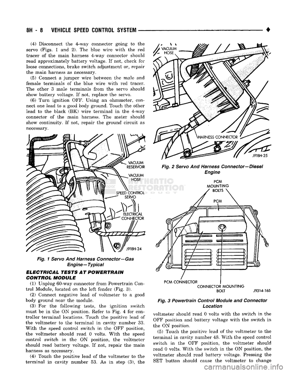
• (4) Disconnect the 4-way connector going to the
servo (Figs. 1 and 2), The blue wire with the red
tracer of the main harness 4-way connector should
read approximately battery voltage. If not, check for loose connections, brake switch adjustment or, repair
the main harness as necessary.
(5) Connect a jumper wire between the male and
female terminals of the blue wire with red tracer.
The other 3 male terminals from the servo should show battery voltage. If not, replace the servo. (6) Turn ignition OFF. Using an ohmmeter, con
nect one lead to a good body ground. Touch the other
lead to the black (BK) wire terminal in the 4-way
connector of the main harness. The meter should
show continuity. If not, repair the ground circuit as
necessary. A
VACUUM
y~
HOSE
J918H-24
Fig.
1 Servo And Harness Connector—Gas
Engine—Typical
ELECTRICAL TESTS AT POWERTRAIN CONTROL MODULE
(1) Unplug 60-way connector from Powertrain Con
trol Module, located on the left fender (Fig. 3).
(2) Connect negative lead of voltmeter to a good
body ground near the module. (3) For the following tests, the ignition switch
must be in the ON position. Refer to Fig. 4 for con
troller terminal locations. Touch the positive lead of
the voltmeter to the terminal in cavity number 33.
With the speed control switch in the OFF position,
the voltmeter should read 0 volts. With the speed
control switch in the ON position, the voltmeter should read battery voltage. If not, repair the main
harness as necessary.
(4) Touch the positive lead of the voltmeter to the
terminal in cavity number 53. As in step (3), the J918H-25
Fig. 2 Servo And Harness Connector—Diesel Engine PCM
MOUNTING
BOLTS
PCM CONNECTOR CONNECTOR MOUNTING BOLT
J9314-165
Fig.
3 Powertrain Control
Module
and
Connector
Location
voltmeter should read 0 volts with the switch in the OFF position and battery voltage with the switch in
the ON position. (5) Touch the positive lead of the voltmeter to the
terminal in cavity number 48. With the speed control switch in the OFF position, the voltmeter should
read 0 volts. With the switch in the ON position, the voltmeter should read battery voltage. Pressing the SET button should cause the voltmeter to change
Page 428 of 1502
•
TURN SIGNALS
AND
HAZARD WARNING FLASHER
8J - 1
CONTENTS
page page
GENERAL
INFORMATION
1
MULTIFUNCTION SWITCH TESTING MULTIFUNCTION SWITCH SERVICE PROCEDURES
2
PROCEDURES
3
GENERAL
INFORMATION
TURN SIGNALS
DESCRIPTION With
the
ignition
key ON and the
multi-function
lever
in its UP or
DOWN position, current flows
through
the:
• turn signal flasher canister • Turn/Hazard switch
• turn indicator lamp
• front
and
rear bulbs. The selected turn signal indicator with front
and
rear turn signal bulbs will flash.
DIAGNOSIS High generator output voltage
can
burn
out
lamps rapidly. (1) Remove
and
inspect fuse
in
cavity
#9 of
fuse
block. Replace
if
necessary.
The
fuse block
is
behind
the lower instrument panel cover under steering wheel. (2) Turn
key to
ACCY. There should
be
battery
voltage
at the
fuse side
of the
turn signal flasher (bottom terminal).
If
not,
repair open circuit
in
wir
ing between fuse
and
flasher.
(3) Replace Turn Flasher with
2
lamp
12
volt rated
flasher that
is
know
to be
good.
The
lamps should
flash. If
not,
replace with original flasher
and
go to
next step.
(4) Measure voltage
at the
Turn/Hazard switch
connector cavity
#17.
Meter should read battery volt
age.
If
OK,
replace Turn/Hazard switch assembly.
If
not, repair open circuit
in
wiring between flasher
and Turn/Hazard switch connector.
HAZARD WARNING SYSTEM
DESCRIPTION
With
the
hazard switch
OUT,
current flows
through
the
• hazard flasher canister
• hazard switch
•
two
front turn signal bulbs
•
two
rear turn signal bulbs
• both indicator bulbs.
All
of the
turn lamps
and
both indicators will
flash.
DIAGNOSIS Hazard switch
in
ON.
The
park
and
stop lamps
should light.
If
not
replace
the 20
amp
fuse
in
fuse
block cavity
#13.
(1) Measure voltage
at
the
fuse side
of
the
flasher
(side terminal). Meter should read battery voltage.
If
not, repair open circuit
in
wiring
to
fuse. (2) Replace Hazard flasher with known good
flasher. Lamps should flash.
If
not, replace with orig
inal flasher
and go
to
next step.
(3) Measure voltage
at the
Turn/Hazard switch
connector cavity #13. Meter should read battery volt
age.
If
not,
repair open circuit
in
wiring
to
hazard
flasher.
TURN
SIGNAL AND HAZARD
WARNING
FLASHER
LOCATION
The turn signal
and
hazard warning flasher
are
both located
on the
fuse block (Fig.
1). The
fuse block is
on the
lower instrument panel cover under
the
steering column.
TURN SIGNALS AND HAZARD WARNING
FLASHER
Page 432 of 1502
•
WINDSHIELD WIPER
AND
WASHER SYSTEMS
8K - 1
WINDSHIELD WIPER
AND
WASHER SYSTEMS
CONTENTS
page
INTERMITTENT WINDSHIELD WIPER FUNCTION AND SWITCH TESTING PROCEDURES
6
TWO SPEED WINDSHIELD WIPER MOTOR
AND
SWITCH TESTING PROCEDURES
1
GENERAL
INFORMATION
The windshield wipers
can be
operated with
the
windshield wiper switch only when
the
ignition switch
is in the
ACCESSORY
or RUN
position.
A
fuse located
in the
fuse block protects
the
circuitry
of
the wiper system
and the
vehicle. The same motor
is
used
for
standard
and
intermit
tent wipe systems. The wiper motor
has
permanent magnet fields.
The
speeds
are
determined
by
current flow
to the
appro
priate
set of
brushes. The intermittent wipe system
in
addition
to low
page
WINDSHIELD WASHERS .. 10
WINDSHIELD WIPER SYSTEM SERVICE PROCEDURES 7
and high speed,
has a
delay mode.
The
delay mode
has
a
range
of 2 to 15
seconds. This
is
accomplished
by
a
variable resistor
in the
wiper switch
and is
con trolled electrically
by a
control module.
The wiper system completes
the
wipe cycle when
the switch
is
turned
OFF. The
blades park
in the
lowest portion
of the
wipe pattern.
Depressing
the
washer knob while
the
system
is in
the
OFF
position, • turns
the
wiper motor
on
• allows
the
motor
to
operate through
3-4
wipe
cy
cles
and
then turn
OFF.
TWO SPEED WINDSHIELD WIPER MOTOR
AND
SWITCH TESTING PROCEDURES INDEX
page
Multifunction
(Two
Speed
Wiper) Switch Testing
Procedures
4
TWO SPEED WIPER MOTOR TESTING PROCEDURES
The following
is a
list
of
general wiper motor sys
tem problems.
It
contains
the
tests that
are to be
per
formed
to
locate
the
faulty part,
and the
corrective action
to be
taken.
The
same motor
is
used
for
stan
dard
and
optional systems.
If the
malfunction
in
volves only
the
Delay mode, switch,
or
wiring, refer
to
the
Intermittent Windshield Wiper Motor
and
Switch Service Procedures.
CONDITION
Motor will
not run in any
switch position.
PROCEDURE
(1) Check
for a
blown fuse
in the
fuse block.
(a)
If
fuse
is
good, proceed
to
step
No. 2.
(b)
If
fuse
is
defective, replace
and
check motor
operation
in all
switch positions.
(c)
If
motor
is
still inoperative
and the
fuse does
not blow, proceed
to
step
No. 2.
page
Two Speed
Wiper Motor Testing Procedures
1
(d)
If
replacement fuse blows, proceed
to
step
No.
5.
(2) Place switch
in low
speed position.
(3) Listen
to
motor.
If you
cannot hear
it
running,
proceed
to
step
No. 4. If you
hear
it
running, check
motor output shaft.
If
output shaft
is not
turning,
re
place motor assembly.
If it is
turning, crank
arm or
drive link
is not
properly connected. Replace worn
parts and/or properly connect drive link
to the
motor output shaft.
(4) Connect
a
voltmeter between motor terminal
"L"
and
ground strap
(Fig. 1). If
there
is no
voltage
or very little voltage (less than
one
volt) present,
move negative test lead from
the
ground strap
to
bat
tery negative terminal.
(a)
If an
increase
in
voltage
is
noticed,
the
prob
lem
is a bad
ground circuit. Make sure
the
motor
mounting
is
free
of
paint
and
that nuts
or
bolts
are
tight.
Page 435 of 1502
8K - 4
WINDSHIELD WIPER
AND
WASHER
SYSTEMS
•
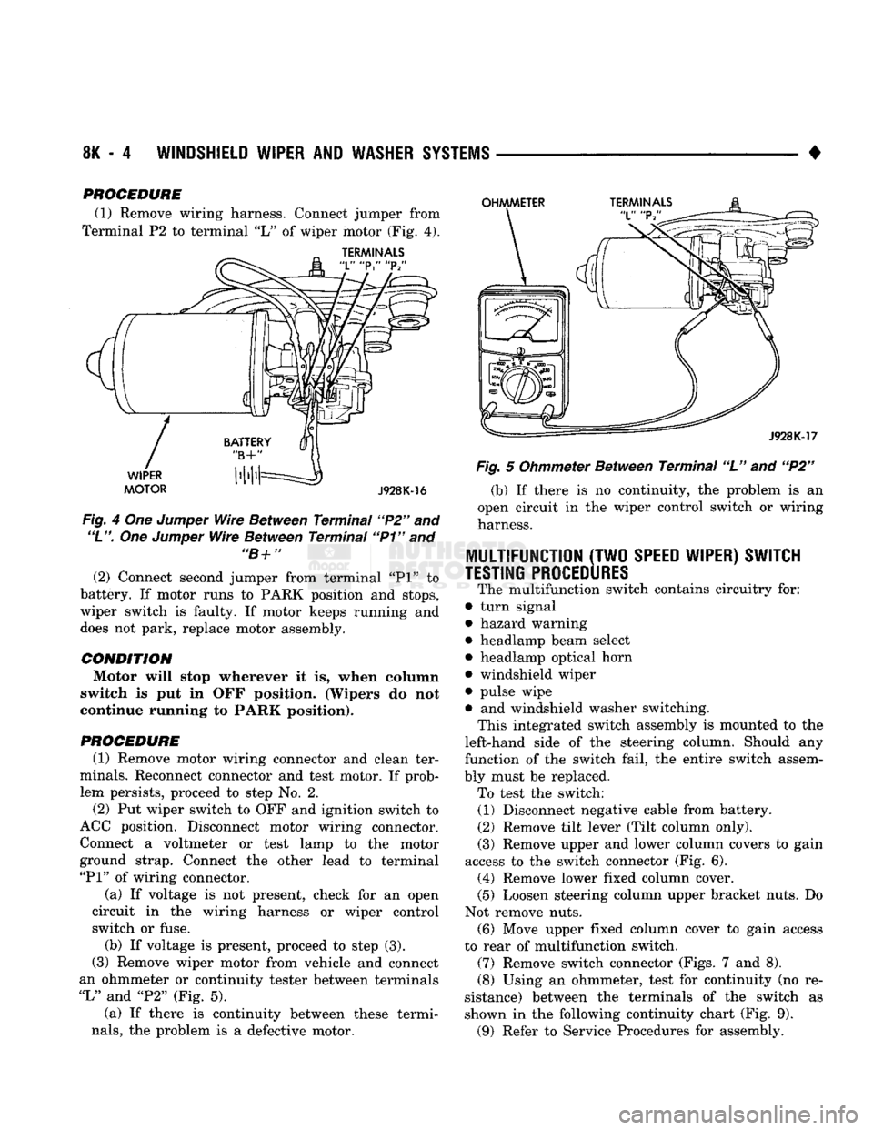
PROCEDURE (1) Remove wiring harness. Connect jumper from
Terminal P2 to terminal "L" of wiper motor (Fig, 4).
TERMINALS
Fig. 4 Om Jumper Wire Between Terminal "P2" and
"L".
One Jumper Wire Between Terminal "P1" and "B+" (2) Connect second jumper from terminal "PI" to
battery. If motor runs to PARK position and stops,
wiper switch is faulty. If motor keeps running and
does not park, replace motor assembly.
CONDITION Motor will stop wherever it is, when column
switch is put in OFF position. (Wipers do not
continue running to PARK position).
PROCEDURE
(1) Remove motor wiring connector and clean ter
minals. Reconnect connector and test motor. If prob lem persists, proceed to step No. 2.
(2) Put wiper switch to OFF and ignition switch to
ACC position. Disconnect motor wiring connector. Connect a voltmeter or test lamp to the motor
ground strap. Connect the other lead to terminal
"PI"
of wiring connector.
(a) If voltage is not present, check for an open
circuit in the wiring harness or wiper control
switch or fuse. (b) If voltage is present, proceed to step (3).
(3) Remove wiper motor from vehicle and connect
an ohmmeter or continuity tester between terminals
"L"
and "P2" (Fig. 5).
(a) If there is continuity between these termi
nals,
the problem is a defective motor. Fig. 5 Ohmmeter Between Terminal "L" and "P2"
(b) If there is no continuity, the problem is an
open circuit in the wiper control switch or wiring
harness.
MULTIFUNCTION
(TWO
SPEED WIPER) SWITCH
TESTING PROCEDURES
The multifunction switch contains circuitry for:
• turn signal
• hazard warning
• headlamp beam select
• headlamp optical horn
• windshield wiper
• pulse wipe
• and windshield washer switching. This integrated switch assembly is mounted to the
left-hand side of the steering column. Should any
function of the switch fail, the entire switch assem
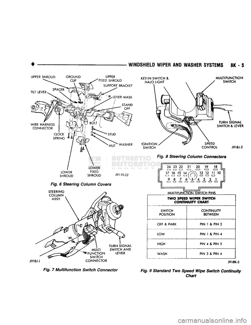
bly must be replaced. To test the switch: (1) Disconnect negative cable from battery.
(2) Remove tilt lever (Tilt column only).
(3)
Remove upper and lower column covers to gain
access to the switch connector (Fig. 6). (4) Remove lower fixed column cover.
(5) Loosen steering column upper bracket nuts. Do
Not remove nuts.
(6)
Move upper fixed column cover to gain access
to rear of multifunction switch.
(7)
Remove switch connector (Figs. 7 and 8).
(8)
Using an ohmmeter, test for continuity (no re
sistance) between the terminals of the switch as
shown in the following continuity chart (Fig. 9).
(9)
Refer to Service Procedures for assembly.
Page 436 of 1502
WINDSHIELD
WIPER
AND
WASHER SYSTEMS
8K - §
UPPER SHROUD GROUND
CLIP UPPER
FIXED SHROUD
SUPPORT BRACKET
STUD NUT WASHER
LOWER
SHROUD LOWER
FIXED
SHROUD J9119-22
Fig.
6 Steering
Column Covers
STEERING
COLUMN
ASSY.
J918J-1
TURN SIGNAL
MULTI SWITCH
AND
FUNCTION LEVER SWITCH
CONNECTOR Fig.
7
Multifunction
Switch
Connector KEY-IN SWITCH
&
HALO LIGHT MULTIFUNCTION
SWITCH IGNITION
SWITCH TURN SIGNAL
SWITCH
&
LEVER
SPEED
CONTROL
J918J-2
Fig.
8 Steering
Column Connectors
MULTIFUNCTION SWITCH PINS
TWO
SPEED
WIPER SWITCH CONTINUITY CHART
SWITCH
POSITION CONTINUITY
BETWEEN
OFF
&
PARK PIN
1 & PIN 2
LOW PIN
1 & PIN 4
HIGH PIN
4 & PIN 5
WASH
PIN
3 & PIN 4 J918K-5
Fig.
9 Standard Two
Speed
Wipe Switch Continuity Chart
Page 438 of 1502
•
WINDSHIELD WIPER
AND
WASHER
SYSTEMS
8K - 7
WINDSHIELD WIPER SYSTEM SERVICE PROCEDURES
INDEX
page
Installation
9
Linkage
Replacement (Fig. 6) 8
Wiper Arm Replacement 7
Wiper Blade Element
Change
7
WIPER
BLADES
Wiper blades exposed to the weather for a long pe
riod of time tend to lose their wiping effectiveness.
Periodic cleaning of the wiper blade is suggested to
remove the accumulation of salt and road film. The wiper blades, arms and windshield should be cleaned
with a sponge or cloth and a mild detergent or nona-
brasive cleaner. If the blades continue to streak or smear, they should be replaced.
WIPER BLADE ELEMENT CHANGE
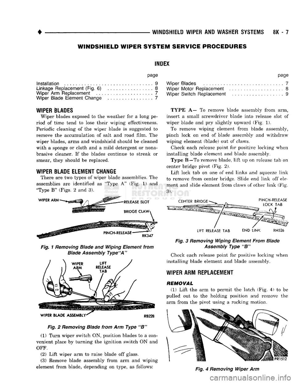
There are two types of wiper blade assemblies. The
assemblies are identified as "Type A" (Fig. 1) and
"Type B" (Figs. 2 and 3).
Fig.
1
Removing
Blade and Wiping Element from
Blade
Assembly
Type'A"
Fig.
2
Removing
Blade from Arm Type "B" (1) Turn wiper switch ON, position blades to a con
venient place by turning the ignition switch ON and
OFF.
(2) Lift wiper arm to raise blade off glass.
(3) Remove blade assembly from arm and wiping
element from blade, depending on type, as follows: page
Wiper Blades 7
Wiper Motor Replacement ................... 8
Wiper Switch Replacement .................. 9
TYPE A— To remove blade assembly from arm,
insert a small screwdriver blade into release slot of
wiper blade and pry slightly upward (Fig. 1).
To remove wiping element from blade assembly,
pinch lock on end of blade assembly and withdraw
wiping element (blade) out of claws.
Check each release point for positive locking when
installing blade element and blade assembly.
Type B—To remove blade, lift up on release tab on
center bridge pivot (Fig. 2).
Lift lock tab on one of end links and squeeze link
to remove from center bridge. Slide end link off ele ment and slide element from claws of other link (Fig,
3).
LIFT RELEASE TAB END LINK RH526
Fig.
3
Removing
Wiping Element From Blade
Assembly
Type "B" Check each release point for positive locking when
installing blade element and blade assembly.
WIPER
ARM REPLACEMENT
REMOVAL
(1) Lift the arm to permit the latch (Fig. 4) to be
pulled out to the holding position and remove the arm from the pivot using a rocking motion.
Fig.
4
Removing
Wiper Arm
Page 444 of 1502
•
LAMPS
LAMPS
8L - 1
CONTENTS
page page
BULB
APPLICATION 11 EXTERIOR
LAMPS
SERVICE
PROCEDURES
... 3
EXTERIOR
LAMPS
1 INTERIOR
LAMPS
10
EXTERIOR LAMPS
GENERAL
INFORMATION Each vehicle is equipped with various lamp assem
blies.
A good ground is necessary for proper lighting operation. When changing lamp bulbs check the socket for
corrosion. Clean corrosion with a wire brush. Coat
the inside of the socket lightly with Mopar® Multi- Purpose Grease or equivalent.
DIAGNOSTIC
PROCEDURES
Always begin any diagnosis by testing all of the
fuses and circuit breakers in the system. Refer to Group 8W, Wiring Diagrams. Conventional and halogen headlamps are inter
changeable. It is recommended that they not be in
termixed on a given vehicle.
MULTI-FUNCTION
SWITCH TESTING
PROCEDURES
The multi-function switch contains electrical cir
cuitry for:
• Headlamp Dimmer Switch
• Passing Lights
• Turn Signals
• Hazard Warning • Windshield Wiper
• Pulse Wiper
• Windshield Washer
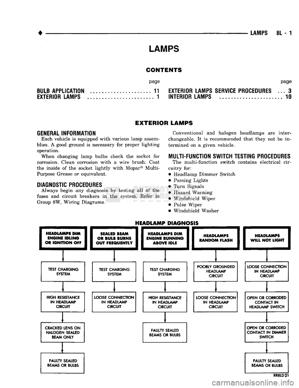
HEADLAMPS
HIM
ENGINE
IDLING
OR
IGNITION
OFF
TEST CHARGING
SYSTEM
HEADLAMP
DIAGNOSIS
SEALED
BEAM
OR
BULB
BURNS
OUT
FREQUENTLY
][
TEST CHARGING SYSTEM
HEADLAMPS
DIM
ENGINE
RUNNING
ABOVE
IDLE
][
TEST CHARGING SYSTEM
HEADLAMPS
RANDOM
FLASH
[
HEADLAMPS
WILL
NOT
LIGHT
POORLY GROUNDED HEADLAMP CIRCUIT
LOOSE
CONNECTION
IN HEADLAMP CIRCUIT
HIGH RESISTANCE IN HEADLAMP CIRCUIT
LOOSE
CONNECTION
IN HEADLAMP CIRCUIT HIGH RESISTANCE
IN HEADLAMP CIRCUIT
LOOSE
CONNECTION
IN HEADLAMP CIRCUIT OPEN OR CORRODED
CONTACT
IN
HEADLAMP SWITCH
CRACKED
LENS ON HALOGEN SEALED BEAM ONLY
FAULTY
SEALED
BEAMS
OR BULBS OPEN OR CORRODED
CONTACT IN DIMMER SWITCH
FAULTY
SEALED
BEAMS
OR BULBS
FAULTY
SEALED
BEAMS
OR BULBS
RR8LD21