1993 DODGE TRUCK check engine light
[x] Cancel search: check engine lightPage 387 of 1502
8E
- 6
INSTRUMENT PANEL
AND
GAUGES
•
(5)
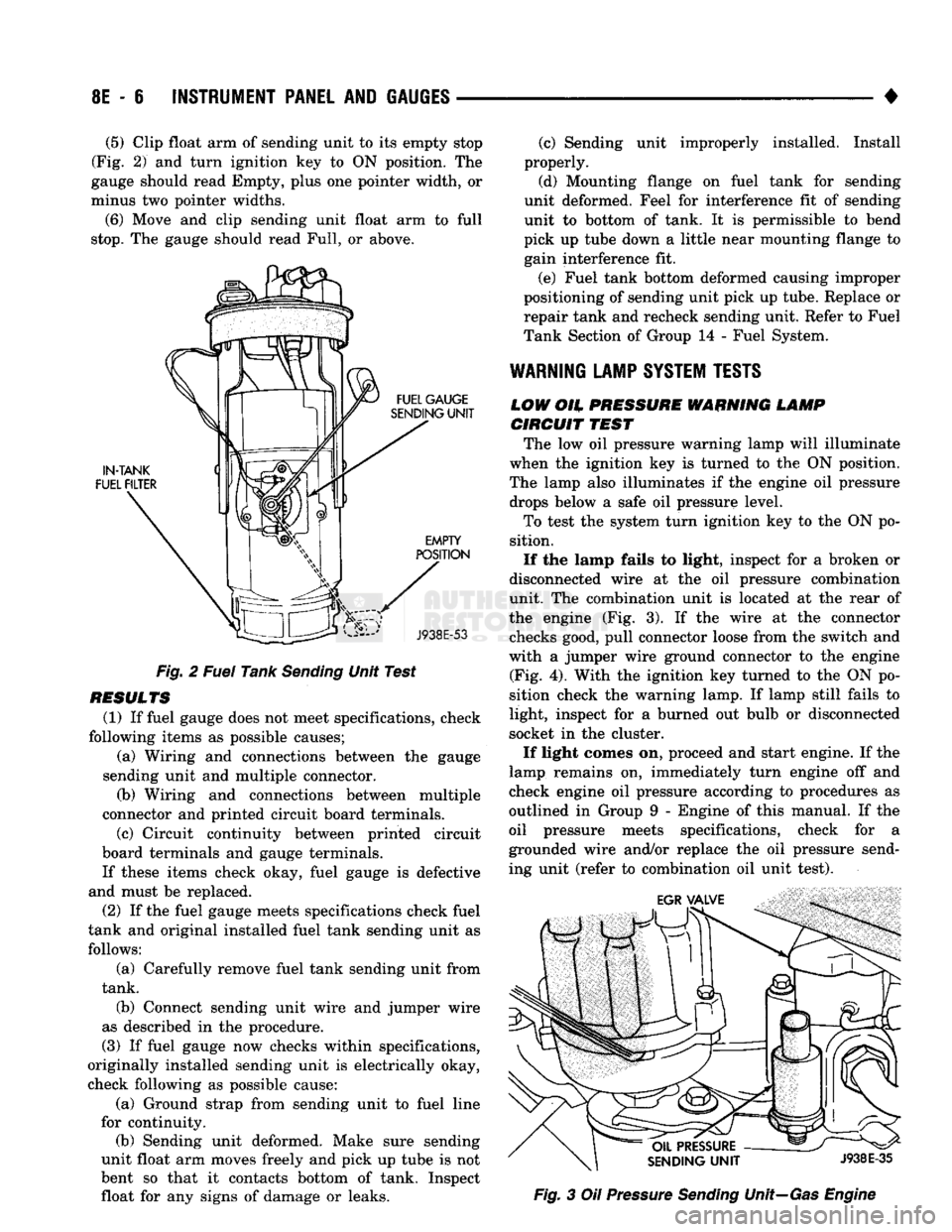
Clip float arm of sending unit to its empty stop
(Fig. 2) and turn ignition key to ON position. The
gauge should read Empty, plus one pointer width, or
minus two pointer widths.
(6) Move and clip sending unit float arm to full
stop.
The gauge should read Full, or above.
Fig. 2 Fuel Tank Sending Unit Test
RESULTS (1) If fuel gauge does not meet specifications, check
following items as possible causes; (a) Wiring and connections between the gauge
sending unit and multiple connector. (b) Wiring and connections between multiple
connector and printed circuit board terminals.
(c) Circuit continuity between printed circuit
board terminals and gauge terminals.
If these items check okay, fuel gauge is defective
and must be replaced.
(2) If the fuel gauge meets specifications check fuel
tank and original installed fuel tank sending unit as follows:
(a) Carefully remove fuel tank sending unit from
tank.
(b) Connect sending unit wire and jumper wire
as described in the procedure.
(3) If fuel gauge now checks within specifications,
originally installed sending unit is electrically okay,
check following as possible cause:
(a) Ground strap from sending unit to fuel line
for continuity. (b) Sending unit deformed. Make sure sending
unit float arm moves freely and pick up tube is not
bent so that it contacts bottom of tank. Inspect float for any signs of damage or leaks. (c) Sending unit improperly installed. Install
properly.
(d) Mounting flange on fuel tank for sending
unit deformed. Feel for interference fit of sending
unit to bottom of tank. It is permissible to bend
pick up tube down a little near mounting flange to gain interference fit.
(e) Fuel tank bottom deformed causing improper
positioning of sending unit pick up tube. Replace or
repair tank and recheck sending unit. Refer to Fuel
Tank Section of Group 14 - Fuel System.
WARNING
LAMP
SYSTEM
TESTS
LOW
OH.
PRESSURE WARNING LAMP CIRCUIT
TEST
The low oil pressure warning lamp will illuminate
when the ignition key is turned to the ON position.
The lamp also illuminates if the engine oil pressure drops below a safe oil pressure level.
To test the system turn ignition key to the ON po
sition.
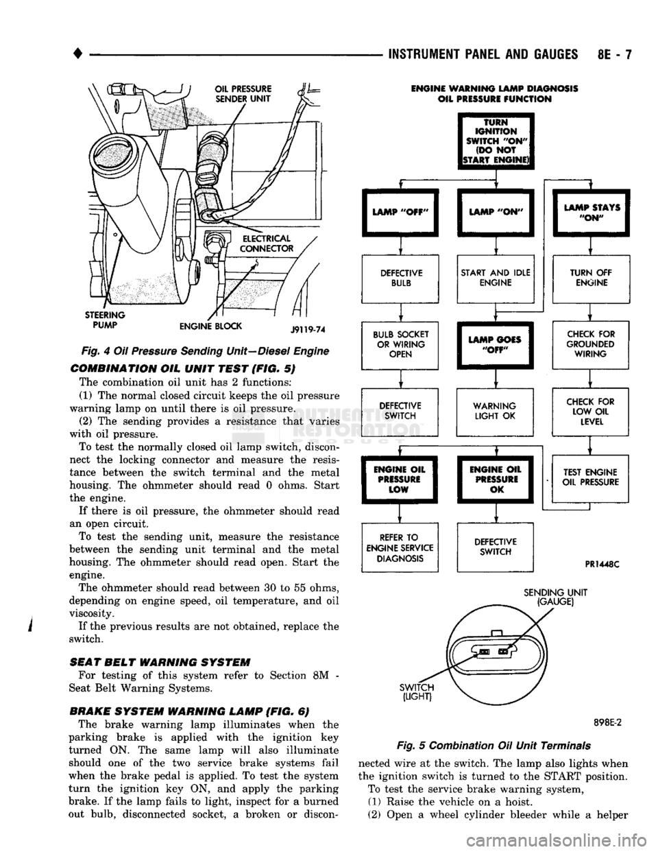
If the lamp fails to light, inspect for a broken or
disconnected wire at the oil pressure combination
unit. The combination unit is located at the rear of
the engine (Fig. 3). If the wire at the connector checks good, pull connector loose from the switch and
with a jumper wire ground connector to the engine (Fig. 4). With the ignition key turned to the ON po
sition check the warning lamp. If lamp still fails to
light, inspect for a burned out bulb or disconnected
socket in the cluster.
If light comes on, proceed and start engine. If the
lamp remains on, immediately turn engine off and
check engine oil pressure according to procedures as
outlined in Group 9 - Engine of this manual. If the
oil pressure meets specifications, check for a
grounded wire and/or replace the oil pressure send
ing unit (refer to combination oil unit test). Fig. 3 Oil Pressure Sending Unit—Gas Engine
Page 388 of 1502
•
INSTRUMENT
PANEL
AND
GAUGES
8E - 7
STEERING PUMP
ENGINE
BLOCK
J9U9-74
Fig.
4 Oil
Pressure
Sending
Unit—Diesel
Engine
COMBINATION
OIL
UNIT
TEST
(FIG. 5)
The combination oil unit has 2 functions:
(1) The normal closed circuit keeps the oil pressure
warning lamp on until there is oil pressure. (2) The sending provides a resistance that varies
with oil pressure.
To test the normally closed oil lamp switch, discon
nect the locking connector and measure the resis
tance between the switch terminal and the metal
housing. The ohmmeter should read 0 ohms. Start
the engine.
If there is oil pressure, the ohmmeter should read
an open circuit. To test the sending unit, measure the resistance
between the sending unit terminal and the metal
housing. The ohmmeter should read open, Start the engine.
The ohmmeter should read between 30 to 55 ohms,
depending on engine speed, oil temperature, and oil
viscosity.
If the previous results are not obtained, replace the
switch.
SEAT
BELT
WARNING
SYSTEM
For testing of this system refer to Section 8M -
Seat Belt Warning Systems.
BRAKE
SYSTEM
WARNING
LAMP
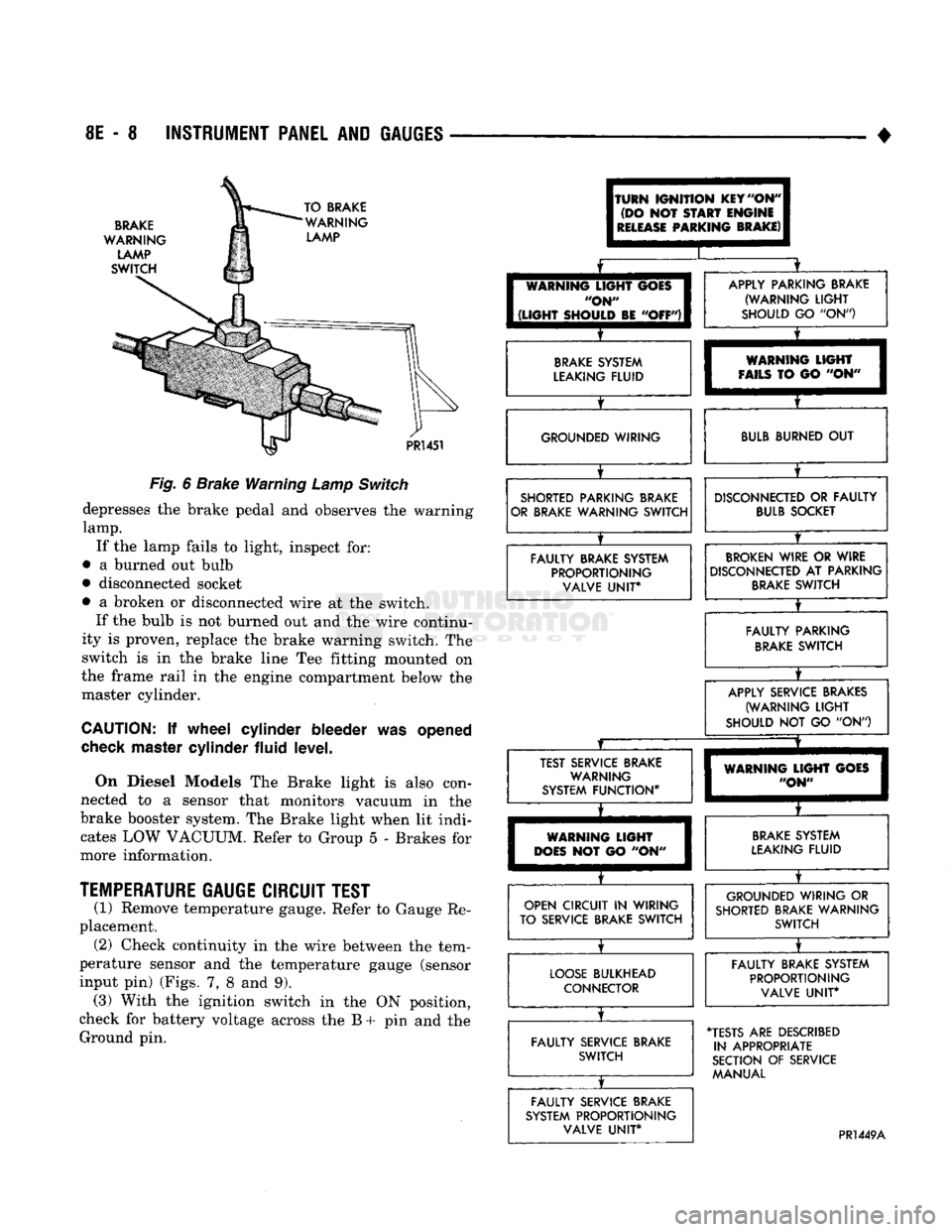
(FIG. 6) The brake warning lamp illuminates when the
parking brake is applied with the ignition key
turned ON. The same lamp will also illuminate should one of the two service brake systems fail
when the brake pedal is applied. To test the system
turn the ignition key ON, and apply the parking
brake. If the lamp fails to light, inspect for a burned
out bulb, disconnected socket, a broken or discon-
ENGINE WARNING LAMP DIAGNOSIS
OIL PRESSURE
FUNCTION
TURN
IGNITION
SWITCH
"OH"
(DO NOT
ISTART ENGINE)! LAMP "OFF'
LAMP "ON"
DEFECTIVE BULB START AND IDLE
ENGINE
BULB SOCKET OR WIRING OPEN LAMP STAYS
"ON" TURN OFF
ENGINE LAMP GOES
"OFF" DEFECTIVE
SWITCH CHECK FOR
GROUNDED WIRING
WARNING
LIGHT
OK CHECK FOR
LOW OIL LEVEL
ENGINE OIL
PRISSURi
LOW
REFER TO
ENGINE SERVICE DIAGNOSIS ENGIM
PRES
0
IE OIL
1
SURE
1
,K I
DEFECTIVE SWITCH TEST ENGINE
OIL PRESSURE
PR1448C
SWITCH
(LIGHT)
SENDING
UNIT
(GAUGE)
898E-2
Fig.
5 Combination Oil Unit Terminals
nected wire at the switch. The lamp also lights when
the ignition switch is turned to the START position. To test the service brake warning system,
(1) Raise the vehicle on a hoist.
(2) Open a wheel cylinder bleeder while a helper
Page 389 of 1502
8E
- 8 INSTRUMENT PANEL AND GAUGES
•
BRAKE
WARNING
LAMP
SWITCH TO BRAKE
WARNING LAMP
PR!
451
Fig.
6
Brake Warning
Lamp
Switch
depresses
the
brake pedal
and
observes
the
warning
lamp.
If
the
lamp fails
to
light, inspect
for:
•
a
burned
out
bulb
• disconnected socket
•
a
broken
or
disconnected wire
at the
switch. If
the
bulb
is not
burned
out and the
wire continu
ity
is
proven, replace
the
brake warning switch.
The
switch
is in the
brake line
Tee
fitting mounted
on
the frame rail
in the
engine compartment below
the
master cylinder.
CAUTION:
If
wheel cylinder bleeder
was
opened
check
master cylinder fluid level.
On Diesel Models
The
Brake light
is
also con
nected
to a
sensor that monitors vacuum
in the
brake booster system.
The
Brake light when
lit
indi cates
LOW
VACUUM. Refer
to
Group
5 -
Brakes
for
more information.
TEMPERATURE
GAUGE CIRCUIT TEST
(1) Remove temperature gauge. Refer
to
Gauge
Re
placement. (2) Check continuity
in the
wire between
the
tem
perature sensor
and the
temperature gauge (sensor
input
pin)
(Figs.
7, 8 and 9).
(3) With
the
ignition switch
in the ON
position,
check
for
battery voltage across
the B + pin and the
Ground
pin.
(TURN
IGNITION
KEY
"ON"
(DO
NOT
START
ENGINE
I
RELEASE
PARKING
BRAKE)
I
I
[
WARNING
LIGHT
GOES
I
"ON"
I
1
(LIGHT
SHOULD
BE
"OFF")!
X
APPLY PARKING BRAKE (WARNING
LIGHT
SHOULD
GO "ON")
BRAKE
SYSTEM
LEAKING FLUID
X
WARNING
LIGHT
FAILS
TO GO "ON" GROUNDED WIRING
BULB
BURNED
OUT
SHORTED PARKING BRAKE
OR BRAKE WARNING SWITCH
X
DISCONNECTED
OR
FAULTY
BULB
SOCKET
FAULTY BRAKE SYSTEM PROPORTIONING VALVE
UNIT*
BROKEN
WIRE
OR
WIRE
DISCONNECTED
AT
PARKING
BRAKE
SWITCH
X
FAULTY PARKING
BRAKE
SWITCH
X
APPLY SERVICE BRAKES
(WARNING
LIGHT
SHOULD
NOT GO "ON")
JZ
X
TEST SERVICE BRAKE WARNING
SYSTEM FUNCTION*
X
WARNING
LIGHT
GOES
"ON"
WARNING
LIGHT
DOES
NOT GO "ON"
BRAKE
SYSTEM
LEAKING FLUID
OPEN CIRCUIT
IN
WIRING
TO SERVICE BRAKE SWITCH
X
GROUNDED WIRING
OR
SHORTED BRAKE WARNING SWITCH
LOOSE
BULKHEAD CONNECTOR
X
FAULTY BRAKE SYSTEM
PROPORTIONING VALVE
UNIT*
FAULTY SERVICE BRAKE SWITCH
X
•TESTS
ARE
DESCRIBED
IN APPROPRIATE
SECTION
OF
SERVICE MANUAL
FAULTY SERVICE BRAKE
SYSTEM PROPORTIONING VALVE
UNIT*
PR1449A
Page 391 of 1502
8E
- 10
INSTRUMENT
PANEL
AND
GAUGES
GROUND
OIL
PRESSURE
SENSOR
INPUT
J908E-70
Fig.
10 Oil Pressure
Sending
Unit—Gas Engine
STEERING
PUMP
ENGINE
BLOCK
J9119-74
Fig.
11 Oil Pressure
Sending
Unit—Diesel Engine
SENDING
UNIT
(GAUGE)
SWITCH
(LIGHT)
898E-2
Fig.
12 Combination Oil Unit Terminals
VOLTAGE
GAUGE
CIRCUIT
TEST
(1) Remove voltage gauge. Refer to Gauge Replace
ment.
Fig.
13 Oil Pressure
Gauge
Pins
r— FUEL
PUMP
SUPPLY
0 INPUT TO
GAUGE
-SENDING
UNIT
GROUND
-FUEL
PUMP
GROUND
J928E-49
Fig.
14 Fuel Tank
Sending
Connector Terminals
FUEL
GAUGE
INPUT
^
GROUND
y
J908E-71
Fig.
15 Fuel
Gauge
Pins
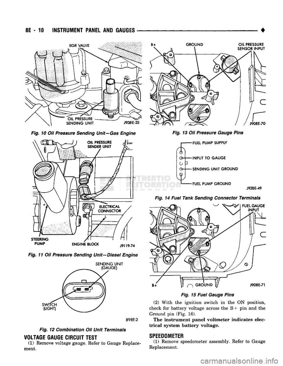
(2) With the ignition switch in the ON position,
check for battery voltage across the B+ pin and the Ground pin (Fig. 16).
The instrument panel voltmeter indicates elec
trical system battery voltage.
SPEEDOMETER
(1) Remove speedometer assembly. Refer to Gauge
Replacement.
Page 397 of 1502
8E - 16 INSTRUMENT PANEL AND GAUGES
• SWITCH AND
PANEL
COMPONENT
SERVICE
INDEX
page
Ash
Tray
20
Cigar
Lighter
........................ 20
Four
Wheel Drive
Indicator
19
Fuse
Block
and
Flashers
................... 19
Glove
Box 21
Heater A/C Control
17
page
Heater Control
16
Hood
Release
19
Illumination
Bulb Replacement
22
Message
Center Module
................... 18
Steering Column Lowering
and
Raising
16
Switches
17
DISCONNECT NEGATIVE CABLE FEOM
BATTERY IN ENGINE COMPAETMENT BE FORE SERVICING INSTRUMENT PANEL.
STEERING COLUMN LOWERING AND RAISING When servicing the instrument panel and the Low
ering and Raising of the steering column is required,
the following is the procedure for doing so: This procedure is not for removing and replac
ing the steering column. Refer to Group - 19 Steering of this manual for the removal and re
placement procedures.
LOWERING STEERING COLUMN
(1) Disconnect negative cable from battery.
(2)
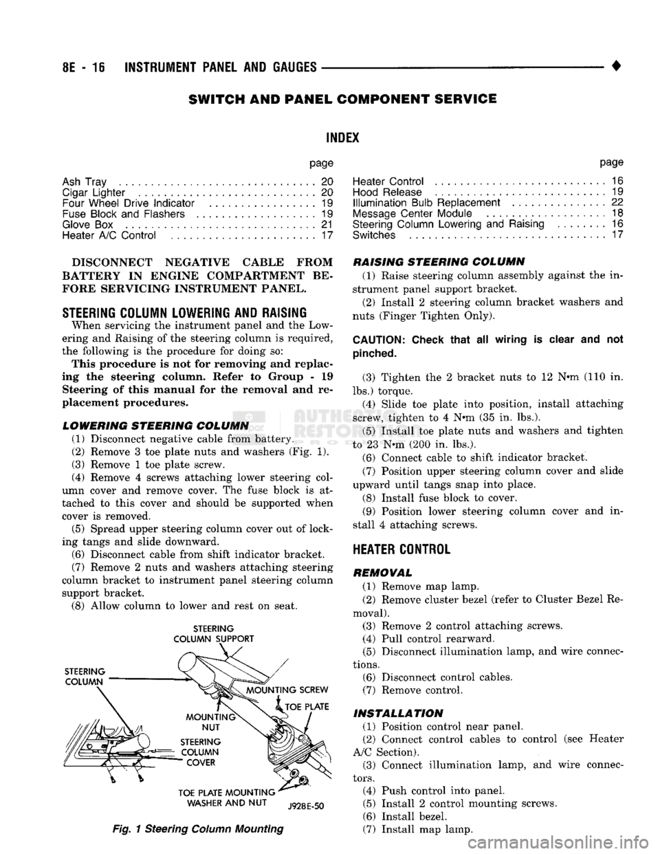
Remove 3 toe plate nuts and washers (Fig. 1).
(3) Remove 1 toe plate screw.
(4) Remove 4 screws attaching lower steering col
umn cover and remove cover. The fuse block is at
tached to this cover and should be supported when cover is removed.
(5) Spread upper steering column cover out of lock
ing tangs and slide downward.
(6)
Disconnect cable from shift indicator bracket.
(7)
Remove 2 nuts and washers attaching steering
column bracket to instrument panel steering column support bracket.
(8)
Allow column to lower and rest on seat.
STEERING
COLUMN SUPPORT
WASHER
AND NUT
Fig.
1 Steering
Column
Mounting
RAISING STEERING COLUMN
(1) Raise steering column assembly against the in
strument panel support bracket. (2) Install 2 steering column bracket washers and
nuts (Finger Tighten Only).
CAUTION:
Check that
all
wiring
is
clear
and not
pinched.
(3) Tighten the 2 bracket nuts to 12 Nnn-(110 in.
lbs.) torque. (4) Slide toe plate into position, install attaching
screw, tighten to 4 N®m (35 in. lbs.).
(5) Install toe plate nuts and washers and tighten
to 23 N*m (200 in. lbs.).
(6)
Connect cable to shift indicator bracket.
(7)
Position upper steering column cover and slide
upward until tangs snap into place.
(8) Install fuse block to cover.
(9)
Position lower steering column cover and in
stall 4 attaching screws.
HEATER CONTROL
REMOVAL
(1) Remove map lamp.
(2) Remove cluster bezel (refer to Cluster Bezel Re
moval). (3) Remove 2 control attaching screws. (4) Pull control rearward.
(5) Disconnect illumination lamp, and wire connec
tions.
(6)
Disconnect control cables.
(7)
Remove control.
INSTALLATION
(1) Position control near panel.
(2) Connect control cables to control (see Heater
A/C Section). (3) Connect illumination lamp, and wire connec
tors.
(4) Push control into panel.
(5) Install 2 control mounting screws.
(6)
Install bezel.
(7)
Install map lamp.
Page 407 of 1502
8F - 4
AUDIO SYSTEMS
• ANTENNA DIAGNOSIS
Turn Ign. Key
to
ACC
Tune
to
Known
Strong AM
Station
f
Check
Antenna Connections
1
1
No
Check
for
Reception Using
A
Test Antenna Repair as
Required*
*Be
Sure
Antenna
is
Properly
Grounded
to
Car.
(Poor
Grounding
of
Antenna
May
Cause
Engine Noise
or
Yes
Static Especially on AM)
Remove
Radio
For
Service
Replace
or
Repair
Defective
Antenna
Or
Lead
in
J928F-4
TIP
OF
MAST
TEST
POINT
RY684
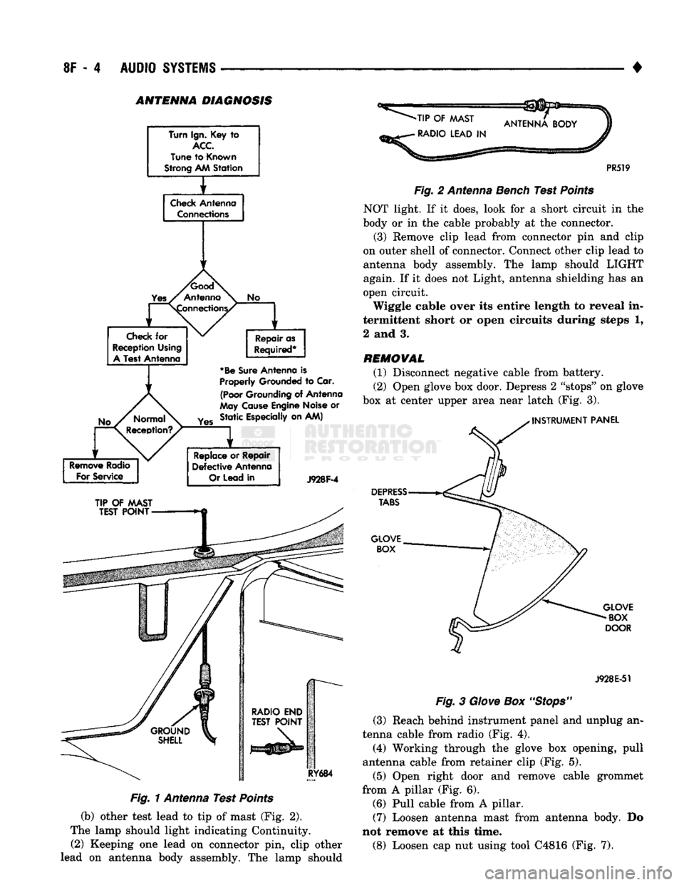
Fig. 1 Antenna Test Points
(b) other test lead to tip of mast (Fig. 2).
The lamp should light indicating Continuity. (2) Keeping one lead on connector pin, clip other
lead on antenna body assembly. The lamp should
-TIP
OF
MAST
•
RADIO LEAD
IN
PR519
Fig.
2 Antenna Bench Test
Points
NOT light. If it does, look for a short circuit in the
body or in the cable probably at the connector.
(3) Remove clip lead from connector pin and clip
on outer shell of connector. Connect other clip lead to
antenna body assembly. The lamp should LIGHT
again. If it does not Light, antenna shielding has an
open circuit.
Wiggle cable over its entire length to reveal in
termittent short or open circuits during steps 1,
2 and 3.
REMOVAL
(1) Disconnect negative cable from battery.
(2) Open glove box door. Depress 2 "stops" on glove
box at center upper area near latch (Fig. 3).
INSTRUMENT
PANEL
DEPRESS
TABS
GLOVE BOX
GLOVE
BOX
DOOR
J928E-51
Fig.
3
Glove
Box
"Stops"
(3) Reach behind instrument panel and unplug an
tenna cable from radio (Fig. 4).
(4) Working through the glove box opening, pull
antenna cable from retainer clip (Fig. 5).
(5) Open right door and remove cable grommet
from A pillar (Fig. 6). (6) Pull cable from A pillar. (7) Loosen antenna mast from antenna body. Do
not remove at this time.
(8) Loosen cap nut using tool C4816 (Fig. 7).
Page 422 of 1502
•
VEHICLE
SPEED
CONTROL SYSTEM
8H - 7
TEST
PROCEDURES
INDEX
page
Checking
for
Diagnostic
Trouble
Code
7
General
Information
7
Inoperative
System
7
Road
Test
7
Speed
Control
Cable Adjustment—Diesel Engine
. 9
Speed
Control
Cable
Attachment
10
GENERAL
INFORMATION
Before starting diagnosis and repair procedures for
a speed control malfunction, verify that the speed
control wire harness is properly connected to all con nectors. Refer to Diagnosis Chart.
ROAD
TEST
Road test vehicle to verify reports of speed control
system malfunction. The road test should include at
tention to the speedometer. Speedometer operation should be smooth and without flutter at all speeds. Flutter in the speedometer indicates a problem
which might cause surging in the speed control sys
tem. The cause of any speedometer deficiencies should be corrected before proceeding.
INOPERATIVE SYSTEM
If road test verifies a system problem and the
speedometer operates properly, check for:
• loose electrical and vacuum connections at the
servo.
• check for correct installation of the vacuum check
valve in the hose from servo to vacuum source (Gas
Engine Only). The word VAC on the valve must
point toward the vacuum source. • corrosion that should be removed from electrical
terminals and a light coating of Mopar Multi-Pur
pose Grease, or equivalent, applied. • secure attachment of both ends of speed control ca
ble.
CHECKING
FOR DIAGNOSTIC TROUBLE CODE
(1) When trying to verify a speed control system
electrical problem, use a DRB II Scan Tool to find
the cause. Refer to Powertrain Diagnostic Procedures manual. If the DRBII is not available, the Diagnostic Trou
ble Code (DTC) may be determined with the follow ing method: (a) With key inserted in ignition switch, cycle
switch to ON position 3 times. On third cycle, leave
switch in ON position. (b) After switch has been cycled 3 times, observe
Malfunction Indicator Lamp (CHECK ENGINE) on instrument cluster. If a DTC is present, the code
page
Speed
Control
Cable Attachment—Servo
10
Stop Lamp Switch Test
9
Vacuum Supply Test
....................... 9
Vehicle Speed
Control
Switch Test
. 9
Vehicle Speed
Control
System
Electrical
Tests
... 7
Vehicle Speed Sensor Test
7
will be displayed in a series of flashes representing
digits.
Three flashes in rapid succession, a slight
pause, then 4 flashes in rapid succession would in dicate DTC 34.
(2) If a DTC 34 is observed, perform the tests in
the sections Electrical Tests at Servo and Electrical
Tests at Powertrain Control Module.
If a DTC 15 is observed, perform the test for a
faulty Vehicle Speed Sensor.
(3) If a fault code 11 is observed (Diesel only), per
form the test for a faulty engine speed sensor. Refer
to the Powertrain Diagnostics Procedures Manual.
(4) Correct any problems found when performing
these tests and recheck for DTC if changes were made.
VEHICLE SPEED SENSOR TEST
For testing of the Vehicle Speed Sensor and related
components refer to the Powertrain Diagnostic Proce
dures manual.
VEHICLE SPEED CONTROL SYSTEM ELECTRICAL
TESTS
Vehicle speed control systems may be tested using
two different methods. One involves the use of the DRBII Scan Tool. If this test method is desired,
please refer to the Powertrain Diagnostic Procedures manual. The other test method uses a voltmeter. The volt
meter method is described in the following tests.
If any information is needed concerning wiring, re
fer to Group 8W - Wiring Diagrams.
CAUTION:
When test probing
for
voltage
or
continuity
at
electrical
connectors, care must
be
taken
not
to
damage connector, terminals,
or
seals.
If
these components
are
damaged,
intermittent
or
complete system
failure
may
occur.
ELECTRICAL
TESTS
AT
SERVO
(1) Turn ignition switch to ON position.
(2) Push speed control switch to ON position.
(3) Connect the negative lead of a voltmeter to a
good chassis ground near the servo.
Page 444 of 1502
•
LAMPS
LAMPS
8L - 1
CONTENTS
page page
BULB
APPLICATION 11 EXTERIOR
LAMPS
SERVICE
PROCEDURES
... 3
EXTERIOR
LAMPS
1 INTERIOR
LAMPS
10
EXTERIOR LAMPS
GENERAL
INFORMATION Each vehicle is equipped with various lamp assem
blies.
A good ground is necessary for proper lighting operation. When changing lamp bulbs check the socket for
corrosion. Clean corrosion with a wire brush. Coat
the inside of the socket lightly with Mopar® Multi- Purpose Grease or equivalent.
DIAGNOSTIC
PROCEDURES
Always begin any diagnosis by testing all of the
fuses and circuit breakers in the system. Refer to Group 8W, Wiring Diagrams. Conventional and halogen headlamps are inter
changeable. It is recommended that they not be in
termixed on a given vehicle.
MULTI-FUNCTION
SWITCH TESTING
PROCEDURES
The multi-function switch contains electrical cir
cuitry for:
• Headlamp Dimmer Switch
• Passing Lights
• Turn Signals
• Hazard Warning • Windshield Wiper
• Pulse Wiper
• Windshield Washer
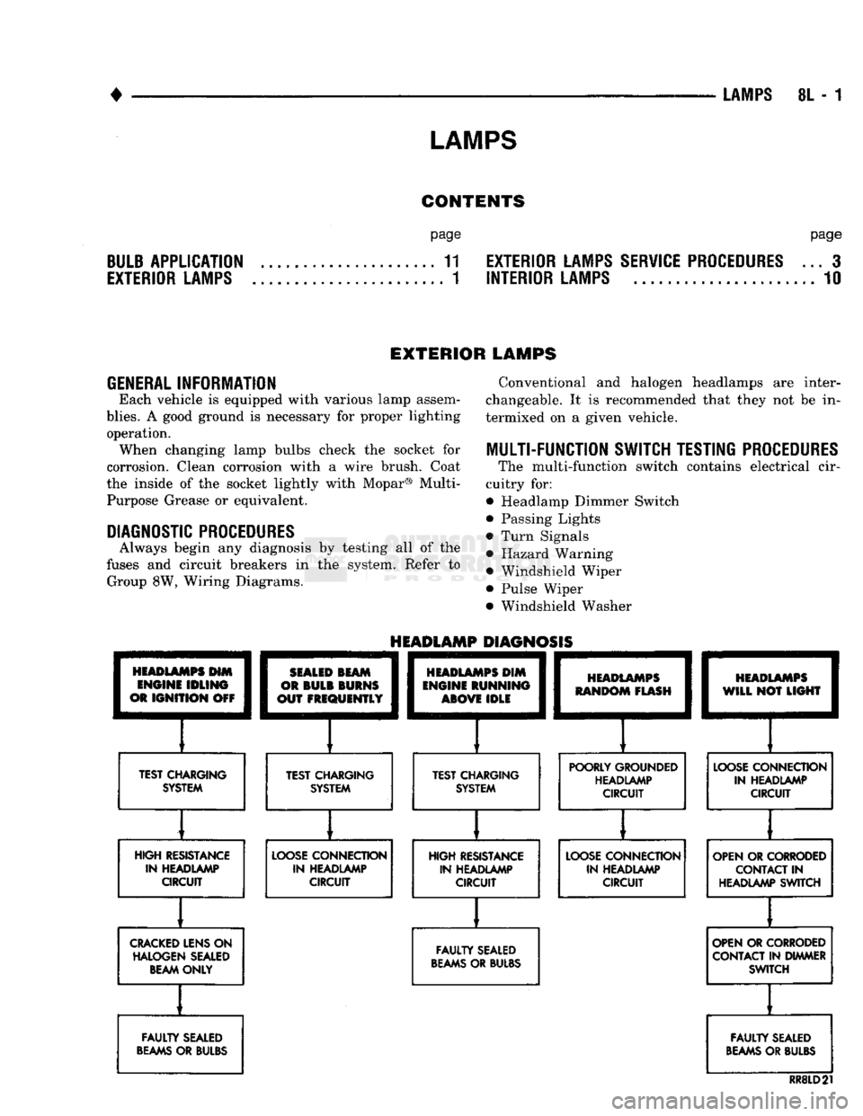
HEADLAMPS
HIM
ENGINE
IDLING
OR
IGNITION
OFF
TEST CHARGING
SYSTEM
HEADLAMP
DIAGNOSIS
SEALED
BEAM
OR
BULB
BURNS
OUT
FREQUENTLY
][
TEST CHARGING SYSTEM
HEADLAMPS
DIM
ENGINE
RUNNING
ABOVE
IDLE
][
TEST CHARGING SYSTEM
HEADLAMPS
RANDOM
FLASH
[
HEADLAMPS
WILL
NOT
LIGHT
POORLY GROUNDED HEADLAMP CIRCUIT
LOOSE
CONNECTION
IN HEADLAMP CIRCUIT
HIGH RESISTANCE IN HEADLAMP CIRCUIT
LOOSE
CONNECTION
IN HEADLAMP CIRCUIT HIGH RESISTANCE
IN HEADLAMP CIRCUIT
LOOSE
CONNECTION
IN HEADLAMP CIRCUIT OPEN OR CORRODED
CONTACT
IN
HEADLAMP SWITCH
CRACKED
LENS ON HALOGEN SEALED BEAM ONLY
FAULTY
SEALED
BEAMS
OR BULBS OPEN OR CORRODED
CONTACT IN DIMMER SWITCH
FAULTY
SEALED
BEAMS
OR BULBS
FAULTY
SEALED
BEAMS
OR BULBS
RR8LD21