1993 DODGE TRUCK check engine light
[x] Cancel search: check engine lightPage 662 of 1502
•
5.2L
ENGINE
9 - 57 (6) With air hose attached to an adapter installed
in No.l spark plug hole, apply 620-689 kPa (90-100
psi) air pressure.
(7) Using Valve Spring Compressor Tool
MD-998772A, compress valve spring and remove re
tainer valve locks and valve spring.
(8) Install seals on the exhaust valve stem and po
sition down against valve guides.
(9) The intake valve stem seals should be pushed
firmly and squarely over the valve guide using the valve stem as a guide. DO NOT force seal against
top of guide. When installing the valve retainer
locks,
compress the spring only enough to install the
locks.
(10) Follow the same procedure on the remaining 7
cylinders using the firing sequence 1-8-4-3-6-5-7-2.
Make sure piston in cylinder is at TDC on the valve
spring that is being removed. (11) Remove adapter from the No.l spark plug
hole.
(12) Install rocker arms.
(13) Install covers and coil wire to distributor.
(14) Install air cleaner. (15) Road test vehicle.
HYDRAULIC TAPPETS
Before disassembling any part of the engine to cor
rect tappet noise, check the oil pressure. If vehicle
has no oil pressure gauge, install a reliable gauge at the pressure sending unit. The pressure should be be
tween 207-552 kPa (30-80 psi) at 3,000 RPM. Check the oil level after the engine reaches normal
operating temperature. Allow 5 minutes to stabilize oil level, check dipstick. The oil level in the pan should never be above the
FULL mark or below the ADD OIL mark on dipstick.
Either of these 2 conditions could be responsible for
noisy tappets.
OIL LEWEL
HIGH
If oil level is above the FULL mark, it is possible
for the connecting rods to dip into the oil. With the
engine running this condition could create foam in
the oil pan. Foam in oil pan would be fed to the hy
draulic tappets by the oil pump causing them to lose
length and allow valves to seat noisily.
LOW Low oil level may allow oil pump to take in air.
When air is fed to the tappets, they lose length
which allows valves to seat noisily. Any leaks on in
take side of oil pump through which air can be drawn will create the same tappet action. Check the
lubrication system from the intake strainer to the
pump cover, including the relief valve retainer cap. When tappet noise is due to aeration, it may be in termittent or constant, and usually more than 1 tap
pet will be noisy. When oil level and leaks have been
corrected, operate the engine at fast idle. Run engine
for a sufficient time to allow all of the air inside the
tappets to be bled out.
TAPPET
NOISE DIAGNOSIS
(1) To determine source of tappet noise, operate en
gine at idle with cylinder head covers removed.
(2) Feel each valve spring or rocker arm to detect
noisy tappet. The noisy tappet will cause the affected
spring and/or rocker arm to vibrate or feel rough in
operation.
Worn valve guides or cocked springs are some
times mistaken for noisy tappets. If such is the case, noise may be dampened by applying side
thrust on the valve spring. If noise is not appre
ciably reduced, it can be assumed the noise is in
the tappet. Inspect the rocker arm push rod sockets and push rod ends for wear.
(3) Valve tappet noise ranges from light noise to a
heavy click. A light noise is usually caused by exces sive leak-down around the unit plunger or by the
plunger partially sticking in the tappet body cylin der. The tappet should be replaced. A heavy click is caused by a tappet check valve not seating or by for
eign particles becoming wedged between the plunger and the tappet body. This will cause the plunger to
stick in the down position. This heavy click will be accompanied by excessive clearance between the
valve stem and rocker arm as valve closes. In either
case,
tappet assembly should be removed for inspec
tion and cleaning.
The valve train generates a noise very much like a
light tappet noise during normal operation. Care
must be taken to ensure that tappets are making the
noise. In general, if more than one tappet seems to
be noisy, its probably not the tappets.
REMOVAL
(1) Remove the air cleaner.
(2) Remove cylinder head cover.
(3) Remove rocker assembly and push rods. Iden
tify push rods to ensure installation in original loca
tion.
(4) Remove intake manifold.
(5) Remove yoke retainer and aligning yokes.
(6) Slide Hydraulic Tappet Remover/Installer Tool
C-4129-A through opening in cylinder head and seat
tool firmly in the head of tappet.
(7) Pull tappet out of bore with a twisting motion.
If all tappets are to be removed, identify tappets to
ensure installation in original location.
(8) If the tappet or bore in cylinder block is scored,
scuffed, or shows signs of sticking, ream the bore to
next oversize. Replace with oversize tappet.
Page 673 of 1502
9
- 68 5.2L
ENGINE
• INSTALLATION
(1) Be sure that compression ring gaps are stag
gered so that neither is in-line with oil ring rail gap.
(2) Before installing the ring compressor, make
sure the oil ring expander ends are butted and the
rail gaps located properly (Fig. 14).
(3) Immerse the piston head and rings in clean en
gine oil. Slide Piston Ring Compressor Tool C-385
over the piston and tighten with the special wrench (part of Tool C-385). Be sure position of rings does
not change during this operation.
(4) Install connecting rod bolt protectors on rod
bolts,
the long protector should be installed on the numbered side of the connecting rod. (5) Rotate crankshaft so that the connecting rod
journal is on the center of the cylinder bore. Be sure connecting rod and cylinder bore number are the same. Insert rod and piston into cylinder bore and
guide rod over the crankshaft journal.
(6) Tap the piston down in cylinder bore, using a
hammer handle. At the same time, guide connecting rod into position on crankshaft journal.
(7) The notch or groove on top of piston must be
pointing toward front of engine. The larger chamfer
of the connecting rod bore must be installed toward
crankshaft journal fillet.
(8) Install rod caps. Be sure connecting rod, con
necting rod cap and cylinder bore number are the same. Install nuts on cleaned and oiled rod bolts and
tighten nuts to 61 N®m (45 ft. lbs.) torque.
(9) Install the oil pan.
(10) Install the cylinder head.
(11) Install the engine into the vehicle.
CRANKSHAFT
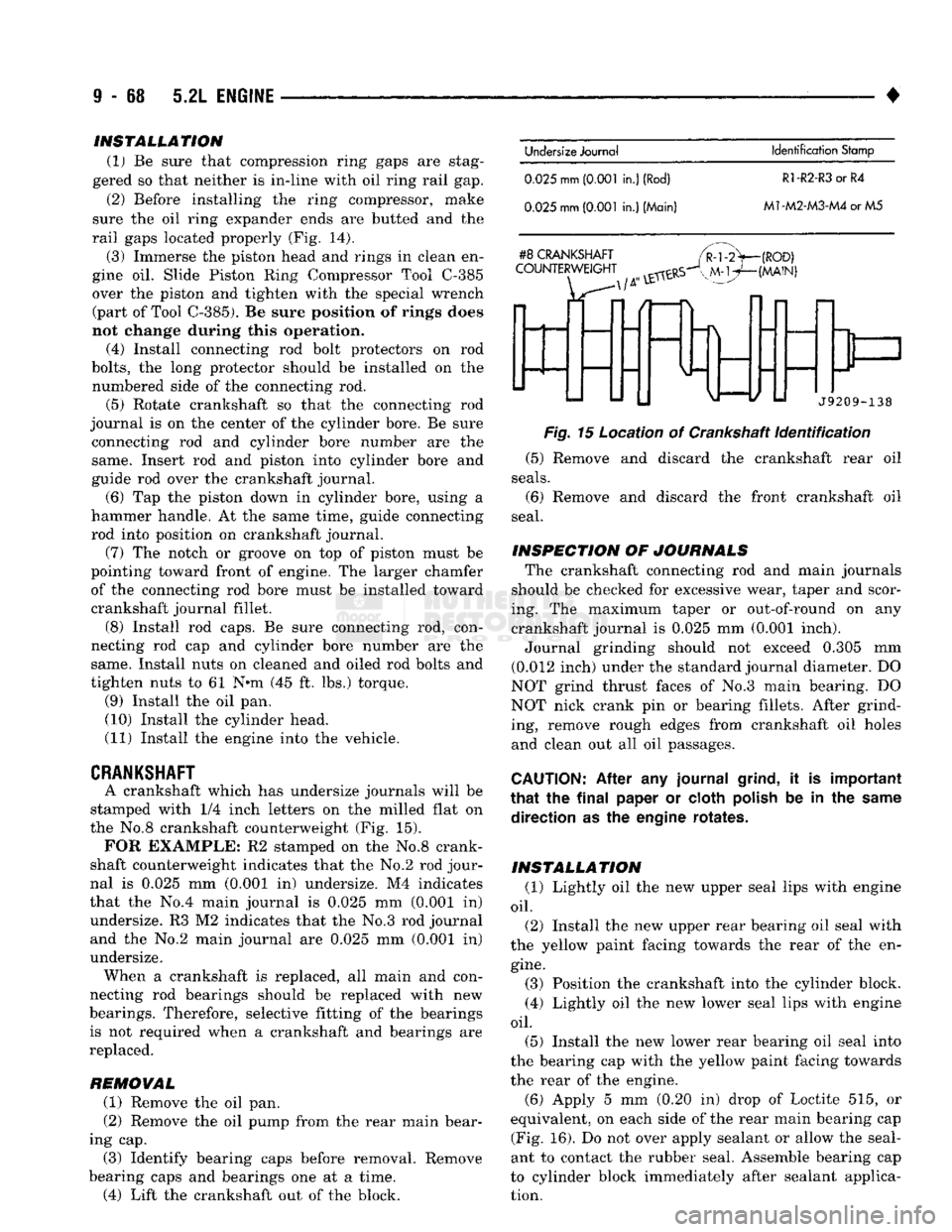
A crankshaft which has undersize journals will be
stamped with 1/4 inch letters on the milled flat on
the No.8 crankshaft counterweight (Fig. 15).
FOR
EXAMPLE: R2 stamped on the No.8 crank
shaft counterweight indicates that the No.2 rod jour
nal is 0.025 mm (0.001 in) undersize. M4 indicates
that the No.4 main journal is 0.025 mm (0.001 in) undersize. R3 M2 indicates that the No.3 rod journal and the No.2 main journal are 0.025 mm (0.Q01 in)
undersize. When a crankshaft is replaced, all main and con
necting rod bearings should be replaced with new
bearings. Therefore, selective fitting of the bearings is not required when a crankshaft and bearings are
replaced.
REMOVAL (1) Remove the oil pan.
(2) Remove the oil pump from the rear main bear
ing cap. (3) Identify bearing caps before removal. Remove
bearing caps and bearings one at a time. (4) Lift the crankshaft out of the block.
Undersize
Journal
Identification
Stamp
0.025
mm
(0.001
in.)
(Rod)
R1-R2-R3
or R4
0.025
mm
(0.001
in.) (Main)
M1-M2-M3-M4
or M5
#8
CRANKSHAFT
COUNTERWEIGHT
(ROD)
(MAIN)
f
J9209-138
Fig.
15 Location of Crankshaft
Identification
(5) Remove and discard the crankshaft rear oil
seals.
(6) Remove and discard the front crankshaft oil
seal.
INSPECTION OF JOURNALS The crankshaft connecting rod and main journals
should be checked for excessive wear, taper and scor
ing. The maximum taper or out-of-round on any crankshaft journal is 0.025 mm (0.001 inch). Journal grinding should not exceed 0.305 mm
(0.012 inch) under the standard journal diameter. DO
NOT grind thrust faces of No.3 main bearing. DO
NOT nick crank pin or bearing fillets. After grind ing, remove rough edges from crankshaft oil holes
and clean out all oil passages.
CAUTION:
After any journal
grind,
it is important
that
the
final
paper or cloth
polish
be in the
same
direction as the engine rotates.
INSTALLATION (1) Lightly oil the new upper seal lips with engine
oil.
(2) Install the new upper rear bearing oil seal with
the yellow paint facing towards the rear of the en
gine.
(3) Position the crankshaft into the cylinder block.
(4) Lightly oil the new lower seal lips with engine
oil.
(5) Install the new lower rear bearing oil seal into
the bearing cap with the yellow paint facing towards
the rear of the engine.
(6)
Apply 5 mm (0.20 in) drop of Loctite 515, or
equivalent, on each side of the rear main bearing cap (Fig. 16). Do not over apply sealant or allow the seal
ant to contact the rubber seal. Assemble bearing cap
to cylinder block immediately after sealant applica tion.
Page 676 of 1502
•
5.2L
ENGINE
9 - 71
(4)
Carefully install
a
new
upper seal
(refer
to
Up
per Seal Replacement
-
Crankshaft
Installed
proce dure above).
(5) Lightly
oil the
new
lower
seal lips
with
engine
oil.
(6) Install
a new
lower seal
in
bearing
cap
with
yellow paint facing
the
rear
of
engine.
(7) Apply
5
mm (0.20
in)
drop
of Loctite 515,
or
equivalent,
on
each side
of
the rear main bearing cap (Fig. 16). Do not over apply sealant or allow the seal
ant
to
contact the rubber seal. Assemble bearing
cap
to cylinder block immediately after sealant applica
tion.
(8)
To align
the
bearing
cap,
use
cap slot, align
ment dowel and cap bolts. Do
not
remove
excess
ma
terial after assembly. Do
not
strike
rear
cap
more
than
2
times
for
proper engagement. (9) Install
the
rear main bearing cap
with
cleaned
and oiled cap bolts. Alternately tighten the
cap
bolts
to 115 N-m (85
ft.
lbs.) torque*.
(10)
Install
oil
pump.
(11)
Apply
Mopar
Silicone Rubber Adhesive
Seal
ant,
or
equivalent,
at
bearing
cap to
block joint
to
provide cap
to
block and oil pan sealing (Fig. 17). Ap ply enough sealant until
a
small amount
is
squeezed
out. Withdraw nozzle and wipe excess sealant
off
the
oil
pan
seal groove. (12) Immediately install
the oil
pan.
CYLINDER BLOCK
Remove
the
engine assembly from
the
vehicle.
DISASSEMBLE
(1)
Remove
the
cylinder head.
(2)
Remove
the oil
pan.
(3)
Remove
the
piston/connecting
rod
assembly.
CLEANING
Clean cylinder block thoroughly
and
check
ail
core
hole plugs for evidence
of
leaking.
INSPECTION
Examine
block
for
cracks or fractures.
The cylinder walls
should
be
checked
for
out-of-
bound and taper with
Cylinder
Bore Indicator Tool
C-119. The
cylinder block should
be
bored
and
honed
with new pistons
and
rings fitted
if:
•
The cylinder bores show more than 0.127
mm
(0.005
inch) out-of-round.
•
The
cylinder bores show
a
taper
of
more than
0.254
mm
(0.010
inch).
•
The cylinder walls are badly scuffed
or
scored. Boring
and
honing
operation should
be
closely
co
ordinated with
the
fitting
of
pistons
and
rings
so
specified clearances
may
be
maintained.
Refer
to
Standard Service Procedures
in the
begin
ning
of
this
Group
for the
proper
honing
of
cylinder
bores.
OIL
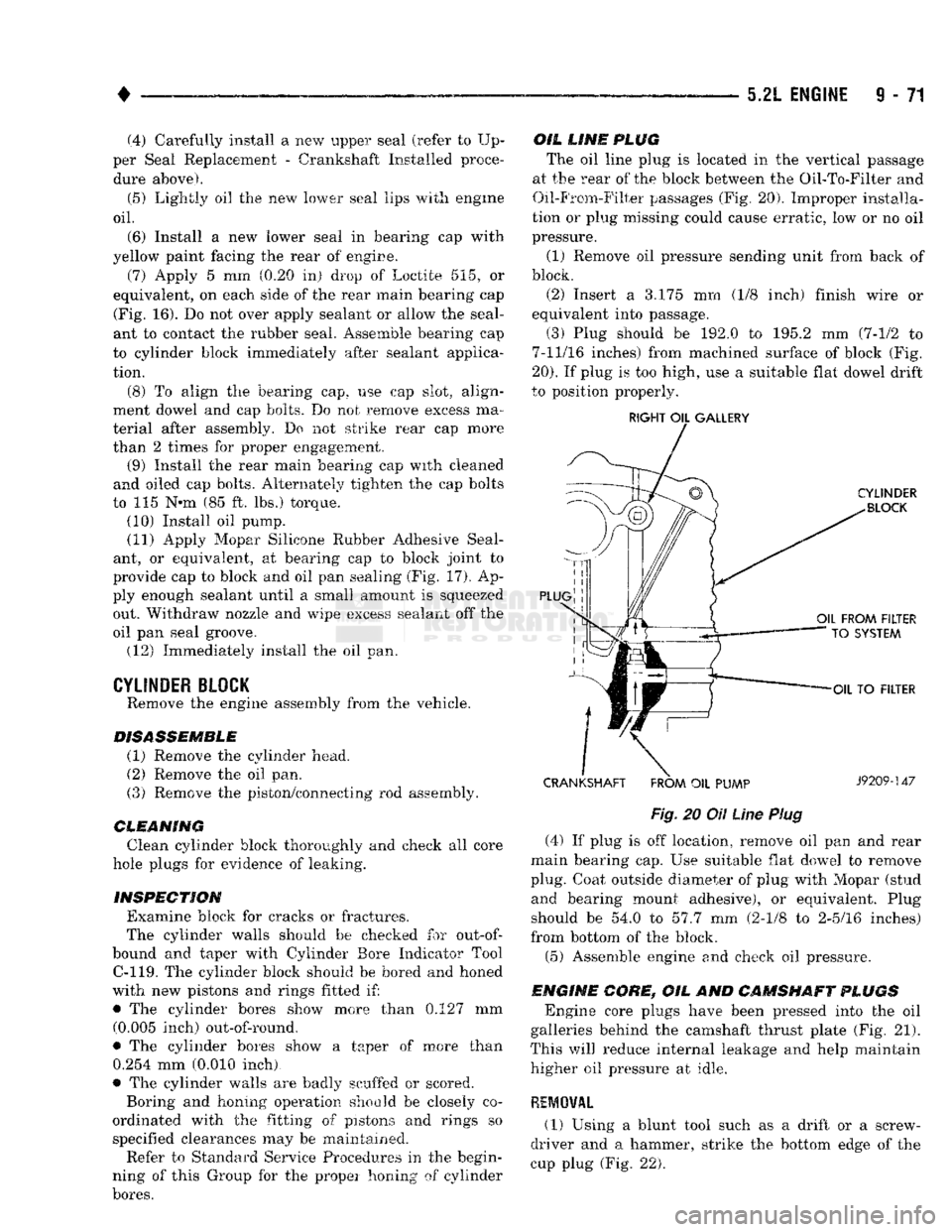
LINE PLUG
The oil
line
plug
is
located in
the
vertical passage
at
the
rear of the
block
between
the Oil-To-Filter and
Oil-From-Filter passages (Fig, 20). Improper installa
tion
or
plug missing could cause erratic, low
or no oil
pressure.
(1) Remove
oil
pressure sending unit from back
of
block.
(2) Insert
a 3.175 mm (1/8
inch) finish wire
or
equivalent into passage.
(3) Plug should
be 192.0 to 195.2 mm
(7-1/2
to
7-11/16 inches) from machined surface
of
block (Fig.
20).
If
plug
is
too high, use
a
suitable flat dowel drift
to position properly.
RIGHT
OIL
GALLERY
CRANKSHAFT FROM
OIL
PUMP
J9209-147
Fig,
20
Oil
Line
Plug
(4)
If
plug
is off
location, remove
oil pan and
rear
main bearing cap. Use suitable flat dowel
to
remove
plug. Coat outside diameter
of
plug with Mopar (stud and bearing mount adhesive),
or
equivalent. Plug
should
be 54.0 to 57.7 mm
(2-1/8
to
2-5/16 inches)
from bottom
of
the block.
(5) Assemble engine
and
check
oil
pressure.
ENGINE CORE,
OIL AND
CAMSHAFT PLUGS
Engine core plugs have been pressed into
the oil
galleries behind
the
camshaft thrust plate (Fig.
21).
This
will
reduce internal leakage
and
help maintain higher
oil
pressure
at
idle.
REMOVAL (1)
Using
a
blunt tool such
as a
drift
or a
screw
driver
and a
hammer, strike
the
bottom edge
of the
cup plug (Fig.
22).
Page 690 of 1502
•
5.9L
ENGINE
9 - 85 sleeve places the valve at the correct height for
checking with a dial indicator.
Fig.
11
Measuring
Valve
Guide
Wear
(c) Move valve to and from the indicator. The to
tal dial indicator reading should not exceed 0.432
mm (0.017 inch). Ream the guides for valves with
oversize stems if dial indicator reading is excessive
or if the stems are scuffed or scored. Service valves with oversize stems are available
(Fig. 12).
Reamer O/S Valve Guide Size
0.076
mm
8.026
-
8.052
mm
(0.003
in.)
(0.316-0.317
in.)
0.381
mm
8.331
-
8.357
mm
(0.015
in.)
(0.328-0.329
in.)
J9309-30
Fig.
12
Reamer
Sizes
Slowly turn reamer by hand and clean guide thor
oughly before installing new valve. Ream the valve
guides from standard to 0.381 mm (0.015 inch).
Use a 2 step procedure so the valve guides are
reamed true in relation to the valve seat:
• Step
1-Ream
to 0.0763 mm (0.003 inch).
• Step 2-Ream to 0.381 mm (0.015 inch).
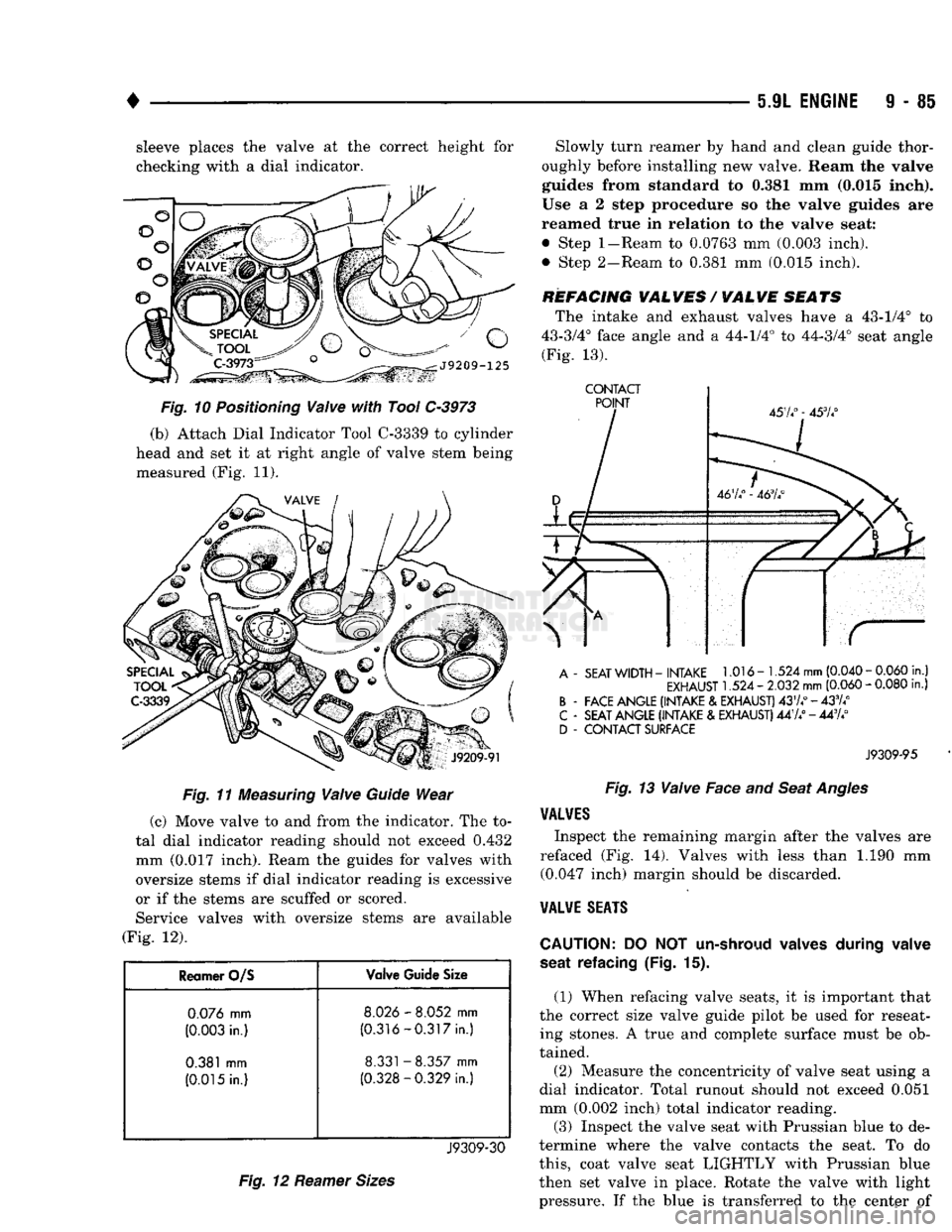
REFACING VALVES / VALVE SEATS The intake and exhaust valves have a 43-1/4° to
43-3/4° face angle and a 44-1/4° to 44-3/4° seat angle (Fig. 13).
CONTACT
A
-
SEAT
WIDTH
-
INTAKE
1.016-1.524
mm
(0.040
-
0.060
in.)
EXHAUST
1.524 -
2.032
mm
(0.060
-
0.080
in.)
B
-
FACE ANGLE (INTAKE
&
EXHAUST)
4374°-433/4°
C
-
SEAT ANGLE (INTAKE
&
EXHAUST)
447/ - 443A°
D
-
CONTACT SURFACE
J9309-95
Fig.
13
Valve
Face and
Seat
Angles
VALVES
Inspect the remaining margin after the valves are
refaced (Fig. 14). Valves with less than 1.190 mm (0.047 inch) margin should be discarded.
VALVE
SEATS
CAUTION:
DO NOT
un-shroud valves during valve
seat refacing
(Fig. 15).
(1) When refacing valve seats, it is important that
the correct size valve guide pilot be used for reseat ing stones. A true and complete surface must be ob
tained.
(2) Measure the concentricity of valve seat using a
dial indicator. Total runout should not exceed 0.051
mm (0.002 inch) total indicator reading.
(3)
Inspect the valve seat with Prussian blue to de
termine where the valve contacts the seat. To do
this,
coat valve seat LIGHTLY with Prussian blue
then set valve in place. Rotate the valve with light pressure. If the blue is transferred to the center of
Page 692 of 1502
•
5.9L ENGINE
9 - 87 (6) With air hose attached to an adapter installed
in No.l spark plug hole, apply 620-689 kPa (90-100
psi) air pressure.
(7) Using Valve Spring Compressor Tool
MD-998772A, compress valve spring and remove re
tainer valve locks and valve spring.
(8) Install seals on the exhaust valve stem and po
sition down against valve guides.
(9) The intake valve stem seals should be pushed
firmly and squarely over the valve guide using the
valve stem as a guide. DO NOT force seal against
top of guide. When installing the valve retainer
locks,
compress the spring only enough to install the
locks.
(10) Follow the same procedure on the remaining 7
cylinders using the firing sequence 1-8-4-3-6-5-7-2.
Make sure piston in cylinder is at TDC on the valve spring that is being removed. (11) Remove adapter from the No.l spark plug
hole.
(12) Install rocker arms.
(13) Install covers and coil wire to distributor.
(14) Install air cleaner.
(15) Road test vehicle.
HYDRAULIC
TAPPETS
Before disassembling any part of the engine to cor
rect tappet noise, check the oil pressure. If vehicle
has no oil pressure gauge, Install a reliable gauge at
the pressure sending unit. The pressure should be be
tween 207-552 kPa (30-80 psi) at 3,000 RPM. Check the oil level after the engine reaches normal
operating temperature. Allow 5 minutes to stabilize
oil level, check dipstick. The oil level in the pan should never be above the
FULL mark or below the ADD OIL mark on dipstick.
Either of these 2 conditions could be responsible for
noisy tappets.
OIL LEVEL
HIGH
If oil level Is above the FULL mark, It is possible
for the connecting rods to dip into the oil. With the engine running this condition could create foam in
the oil pan. Foam in oil pan would be fed to the hy
draulic tappets by the oil pump causing them to lose
length and allow valves to seat noisily.
LOW
Low oil level may allow oil pump to take in air.
When air is fed to the tappets, causes them to lose length and allows valves to seat noisily. Any leaks
on intake side of oil pump through which air can be
drawn will create the same tappet action. When tap
pet noise is due to aeration, it may be intermittent or constant, and usually more than 1 tappet will be
noisy. When oil level and leaks have been corrected, engine should be operated at fast idle for sufficient
time.
This allows all of the air inside of the tappets
to be bled out.
TAPPET NOISE DIAGNOSIS
(1) To determine source of tappet noise, operate en
gine at idle with cylinder head covers removed. (2) Feel each valve spring or rocker arm to detect
noisy tappet. The noisy tappet will cause the affected
spring and/or rocker arm to vibrate or feel rough in
operation.
Worn valve guides or cocked springs are some
times mistaken for
noisy tappets.
If such is the
case,
noise may be dampened by applying side
thrust on the
valve
spring. If noise is not appre ciably reduced, it can be assumed the noise Is in
the tappet. Inspect the rocker arm push rod sockets and
push
rod ends for wear.
(3) Valve tappet noise ranges from light noise to a
heavy click. A light noise is usually caused by exces
sive leak-down around the unit plunger or by the
plunger partially sticking in the tappet body cylin der. The tappet should be replaced. A heavy click is
caused by a tappet check valve not seating or by for
eign particles becoming wedged between the plunger and the tappet body. This will cause the plunger to
stick in the down position. This heavy click will be
accompanied by excessive clearance between the
valve stem and rocker arm as valve closes. In either
case,
tappet assembly should be removed for inspec
tion and cleaning.
The valve train generates a noise very much like a
light tappet noise during normal operation. Care
must be taken to ensure that tappets are making the
noise. In general, if more than one tappet seems to
be noisy, its probably not the tappets.
REMOVAL
(1) Remove the air cleaner.
(2) Remove cylinder head cover.
(3) Remove rocker assembly and push rods. Iden
tify push rods to ensure Installation in original loca
tion.
(4) Remove Intake manifold.
(5) Remove yoke retainer and aligning yokes.
(6) Slide Hydraulic Tappet Remover/Installer Tool
C-4129-A through opening in cylinder head and seat
tool firmly in the head of tappet.
(7) Pull tappet out of bore with a twisting motion.
If all tappets are to be removed, identify tappets to ensure installation in original location.
(8) If the tappet or bore in cylinder block is scored,
scuffed, or shows signs of sticking, ream the bore to
next oversize. Replace with oversize tappet.
Page 703 of 1502
(2) Before installing the ring compressor, make
sure the oil ring expander ends are butted and the
rail gaps located properly (Fig. 14).
(3) Immerse the piston head and rings in clean en
gine oil. Slide Piston Ring Compressor Tool C-385
over the piston and tighten with the special wrench (part of Tool C-385). Be
sure position
of
rings does
not change
during this operation.
(4) Install connecting rod bolt protectors on rod
bolts,
the long protector should be installed on the numbered side of the connecting rod. (5) Rotate crankshaft so that the connecting rod
journal is on the center of the cylinder bore. Be sure connecting rod and cylinder bore number are the same. Insert rod and piston into cylinder bore and
guide rod over the crankshaft journal.
(6) Tap the piston down in cylinder bore, using a
hammer handle. At the same time, guide connecting
rod into position on crankshaft journal. (7) The notch or groove on top of piston must be
pointing toward front of engine. The larger chamfer of the connecting rod bore must be Installed toward
crankshaft journal fillet.
(8) Install rod caps. Install nuts on cleaned and
oiled rod bolts and tighten nuts to 61 N*m (45 ft. lbs.)
torque. (9) Install the oil pan.
(10) Install the cylinder head.
(11) Install the engine Into the vehicle.
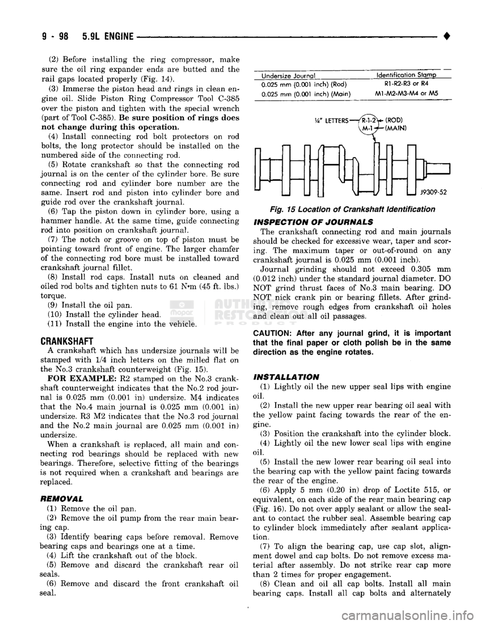
CRANKSHAFT
A crankshaft which has undersize journals will be
stamped with 1/4 inch letters on the milled flat on
the No.3 crankshaft counterweight (Fig. 15). FOR EXAMPLE: R2 stamped on the No.3 crank
shaft counterweight indicates that the No.2 rod jour
nal is 0.025 mm (0.001 in) undersize. M4 indicates
that the No.4 main journal is 0.025 mm (0.001 in) undersize. R3 M2 indicates that the No.3 rod journal
and the No.2 main journal are 0.025 mm (0.001 In)
undersize. When a crankshaft is replaced, all main and con
necting rod bearings should be replaced with new
bearings. Therefore, selective fitting of the bearings is not required when a crankshaft and bearings are
replaced.
REMOVAL
(1) Remove the oil pan.
(2) Remove the oil pump from the rear main bear
ing cap.
(3) Identify bearing caps before removal. Remove
bearing caps and bearings one at a time. (4) Lift the crankshaft out of the block.
(5) Remove and discard the crankshaft rear oil
seals.
(6) Remove and discard the front crankshaft oil
seal. Undersize Journal
Identification
Stamp
0.025
mm
(0.001
inch) (Rod)
0.025
mm
(0.001
inch) (Main)
R1-R2-R3
or R4
M1-AA2-M3-AA4
or AA5
V/
LETTERS—/R-l-2>
(ROD)
VM-WHMAIN)
J9309-52
Fig.
15 Location of Crankshaft
identification
INSPECTION
OF
JOURNALS
The crankshaft connecting rod and main journals
should be checked for excessive wear, taper and scor
ing. The maximum taper or out-of-round on any
crankshaft journal is 0.025 mm (0.001 inch).
Journal grinding should not exceed 0.305 mm
(0.012 inch) under the standard journal diameter. DO
NOT grind thrust faces of No.3 main bearing. DO
NOT nick crank pin or bearing fillets. After grind ing, remove rough edges from crankshaft oil holes
and clean out all oil passages.
CAUTION:
After any journal
grind,
it is important
that
the
final
paper or cloth
polish
be in the
same
direction as the engine rotates.
INSTALLATION
(1) Lightly oil the new upper seal lips with engine
oil.
(2) Install the new upper rear bearing oil seal with
the yellow paint facing towards the rear of the en
gine.
(3) Position the crankshaft into the cylinder block.
(4) Lightly oil the new lower seal lips with engine
oil.
(5) Install the new lower rear bearing oil seal into
the bearing cap with the yellow paint facing towards the rear of the engine. (6) Apply 5 mm (0.20 in) drop of Loctite 515, or
equivalent, on each side of the rear main bearing cap (Fig. 16). Do not over apply sealant or allow the seal
ant to contact the rubber seal. Assemble bearing cap
to cylinder block immediately after sealant applica
tion.
(7) To align the bearing cap, use cap slot, align
ment dowel and cap bolts. Do not remove excess ma
terial after assembly. Do not strike rear cap more
than 2 times for proper engagement.
(8) Clean and oil all cap bolts. Install all main
bearing caps. Install all cap bolts and alternately
Page 735 of 1502
9
- 130 5.9L
(DIESEL) ENGINE
• CAMSHAFT BORE DIAMETER
MAX.
54.133
mm
(2.1312
inch)
J9109-78
Fig.
3 Camshaft
Bores
BORE DIAMETER
MAX. 16.055 mm (0.632 inch)
J9109-79
Fig.
4
Tappet
Bore
Diameter
(3) Cover the lube holes in the top of the block
with waterproof tape.
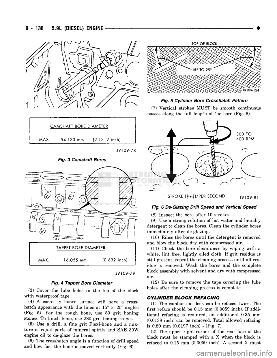
(4) A correctly honed surface will have a cross-
hatch appearance with the lines at 15° to 25° angles (Fig. 5). For the rough hone, use 80 grit honing
stones. To finish hone, use 280 grit honing stones.
(5) Use a drill, a fine grit Flexi-hone and a mix
ture of equal parts of mineral spirits and SAE 30W engine oil to de-glaze the bores.
(6) The Crosshatch angle is a function of drill speed
and how fast the hone is moved vertically (Fig. 6).
TOP
OF
BLOCK
Fig.
5 Cylinder
Bore
Crosshatch
Pattern
(7) Vertical strokes MUST be smooth continuous
passes along the full length of the bore (Fig. 6).
1
STROKE
(f+|)/PER
SECOND
Fig.
6 De-Glazing Drill
Speed
and
Vertical
Speed
(8) Inspect the bore after 10 strokes.
(9) Use a strong solution of hot water and laundry
detergent to clean the bores. Clean the cylinder bores
immediately after de-glazing.
(10) Rinse the bores until the detergent is removed
and blow the block dry with compressed air. (11) Check the bore cleanliness by wiping with a
white, lint free, lightly oiled cloth. If grit residue is still present, repeat the cleaning process until all res
idue is removed. Wash the bores and the complete
block assembly with solvent and dry with compressed air.
(12) Be sure to remove the tape covering the lube
holes after the cleaning process is complete.
CYLINDER BLOCK REFACING
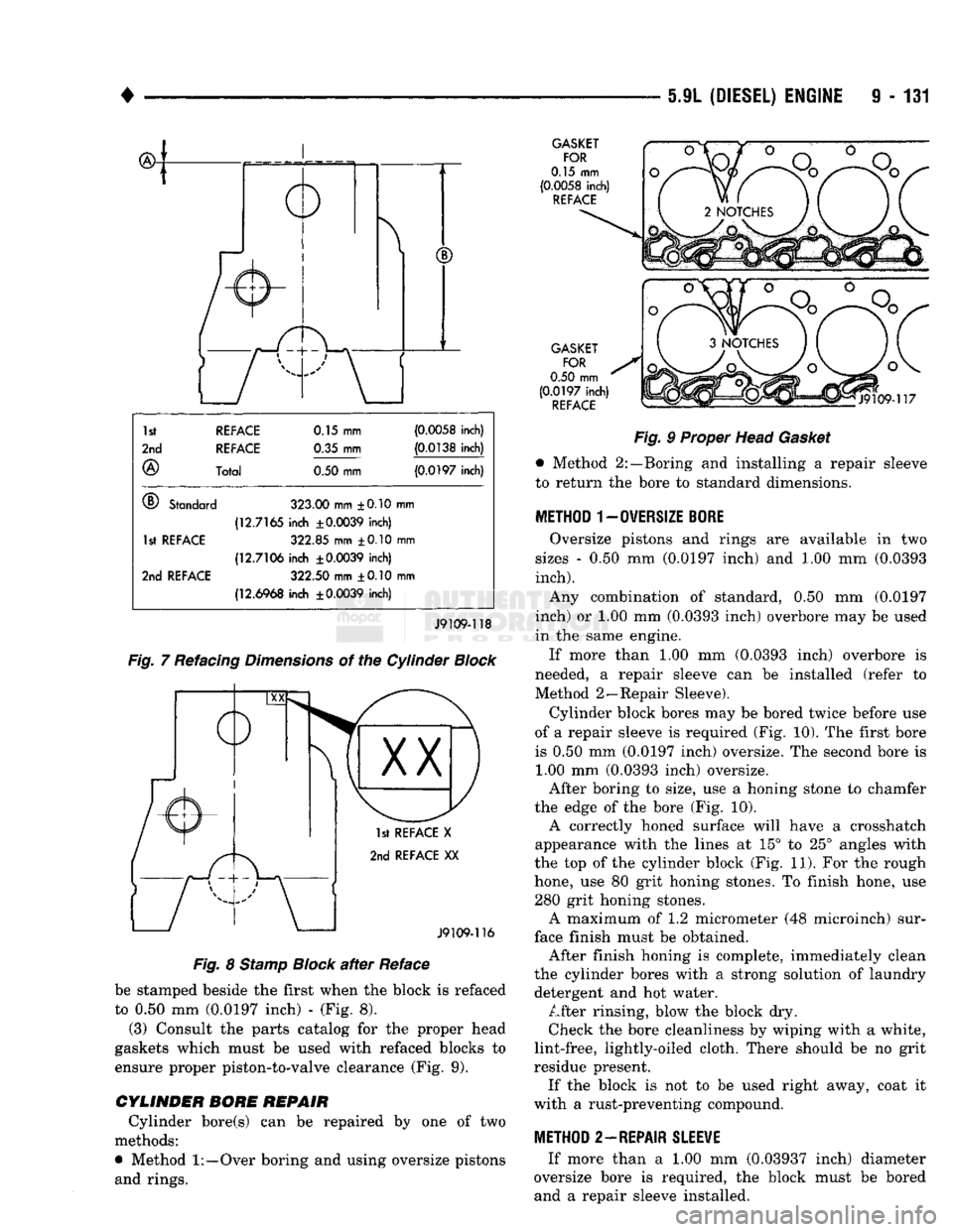
(1) The combustion deck can be refaced twice. The
first reface should be 0.15 mm (0.0059 inch). If addi
tional refacing is required, an additional 0.35 mm (0.0138 inch) can be removed. Total allowed refacing
is 0.50 mm (0.0197 inch) - (Fig. 7).
(2) The upper right corner of the rear face of the
block must be stamped with a X when the block is refaced to 0.15 mm (0.0059 inch). A second X must
Page 736 of 1502
•
5.9L (DIESEL) ENGINE
9 - 131
1st REFACE
0.15 mm
(0.0058
inch)
2nd REFACE
0.35 mm
(0.0138
inch)
®
Total
0.50
mm
(0.0197
inch)
®
Standard
323.00
mm ±0.10 mn i
(12.7165
inch
±0.0039
inch)
1st
RE
FACE
322.85 mm ±0.10 mm
(12.7106
inch
±0.0039
inch)
2nd
REFACE
322.50
mm ±0.10 mn i
(12.6968
inch
±0.0039
inch)
J9109-118
Fig.
7 Refacing
Dimensions
of the Cylinder
Block
1st REFACE
X
2nd REFACE
XX
J9109-116
Fig.
8
Stamp
Block
after
Reface
be stamped beside the first when the block is refaced
to 0.50 mm (0.0197 inch) - (Fig. 8). (3) Consult the parts catalog for the proper head
gaskets which must be used with refaced blocks to
ensure proper piston-to-valve clearance (Fig. 9).
CYLINDER BORE REPAIR Cylinder bore(s) can be repaired by one of two
methods:
•
Method
1:—Over
boring and using oversize pistons and rings.
GASKET
FOR
0.15 mm
(0.0058
inch)
REFACE
GASKET FOR
0.50
mm
(0.0197
inch)
REFACE
Fig.
9 Proper Head
Gasket
•
Method 2:—Boring and installing a repair sleeve
to leturn the bore to standard dimensions.
METHOD 1-0WERS1ZE
BORE
Oversize pistons and rings are available in two
sizes - 0.50 mm (0.0197 inch) and 1.00 mm (0.0393
inch).
Any combination of standard, 0.50 mm (0.0197
inch) or 1.00 mm (0.0393 inch) overbore may be used
in the same engine.
If more than 1.00 mm (0.0393 inch) overbore is
needed, a repair sleeve can be installed (refer to
Method 2—Repair Sleeve).
Cylinder block bores may be bored twice before use
of a repair sleeve is required (Fig. 10). The first bore
is 0.50 mm (0.0197 inch) oversize. The second bore is 1.00 mm (0.0393 inch) oversize.
After boring to size, use a honing stone to chamfer
the edge of the bore (Fig. 10). A correctly honed surface will have a Crosshatch
appearance with the lines at 15° to 25° angles with
the top of the cylinder block (Fig. 11). For the rough
hone, use 80 grit honing stones. To finish hone, use 280 grit honing stones. A maximum of 1.2 micrometer (48 microinch) sur
face finish must be obtained. After finish honing is complete, immediately clean
the cylinder bores with a strong solution of laundry detergent and hot water. After rinsing, blow the block dry. Check the bore cleanliness by wiping with a white,
lint-free, lightly-oiled cloth. There should be no grit
residue present. If the block is not to be used right away, coat it
with a rust-preventing compound.
METHOD 2—REPAIR
SLEEWE
If more than a 1.00 mm (0.03937 inch) diameter
oversize bore is required, the block must be bored and a repair sleeve installed.