Page 1468 of 1502
•
HEATING AND AIR CONDITIONING 24 - 31
SOLID
LINE
INDICATES ENGINE
VACUUM
„
VIOLET
CHECK
VALVE f
SOLID
LINE INDICATES
ENGINE
VACUUM
VIOLET
YELLOW
I ACTUATOR ^OUTSIDE
AIR
OFF, MAX A/C
A/C,
VENT
SOLID
LINE
INDICATES
ENGINE
VACUUM VIOLET
RED
/ I
CHECK
VALVE I • DEFROSTER-*-*-
H5WN
RESTRICTOR
DARK
GREEN
AIR/COND.
t
ACTUATOR
I
HEATING
WATER VALVE
ACTUATOR ^
| •
ON
-*-^OFF
YELLOW
HEAT
ACTUATOR
LIGHT
GREEN
RECIRCULATING
GRAY ACTUATOR
OUTSIDE
AIR
SOLID
LINE INDICATES
ENGINE
VACUUM VIOLET
ACTUATOR HEAT
* PUSH BUTTON CONTROL
VACUUM SWITCH
** RESTRICTOR IS PART OF VACUUM CONNECTOR AND NOT VISIBLE ACTUATOR
OUTSIDE
RN1001
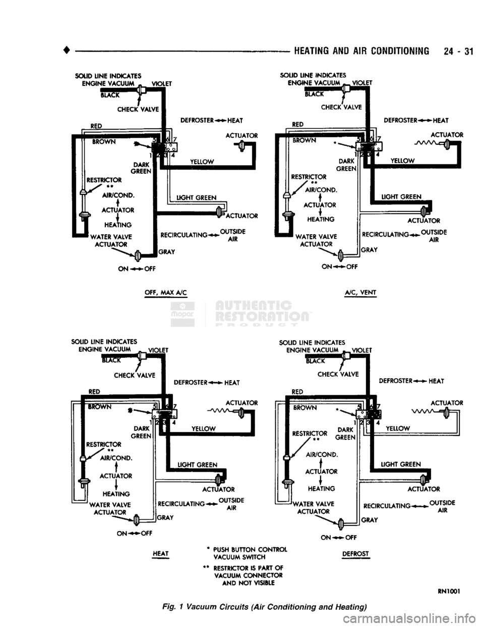
Fig. 1
Vacuum
Circuits
(Air
Conditioning
and
Heating)
Page 1478 of 1502
•
EMISSION
CONTROL
SYSTEMS
25
- 1
CONTENTS
page page
AIR INJECTION
SYSTEM-o
9L
HDC-GAS EVAPORATIVE EMISSION CONTROLS
6
ENGINE
15
EXHAUST EMISSION CONTROLS
10
COMPONENT
REMOVAL/INSTALLATION
17
GENERAL INFORMATION
1
GENERAL
INFORMATION
Throughout this group, references are made
to
par
ticular vehicle models
by
alphabetical designation
or
by the particular vehicle nameplate.
A
chart showing a breakdown
of
alphabetical designations
is
included
in
the
Introduction section
at
the
beginning
of
this
manual.
The 5.9L (V-8) gas powered engine will
be
referred
to
in
this group
as
either the: LDC (Light Duty Cy cle)
or
HDC (Heavy Duty Cycle) engine.
The
HDC
engine can
be
easily identified
by
the
use
of
an en
gine mounted
air
injection pump. The 3.9L/5.2L/5.9L
LDC engine will not use
an
air
injection pump.
Maintenance requirements for LDC and HDC emis
sion systems differ because
of
different load
and
op
erating conditions. This section will cover emission control systems
for
the 3.9L (V-6), 5.2L (V-8), 5.9L LDC (V-8), 5.9L HDC (V-8) and 5.9L (in-line six cylinder) diesel engines.
SERVICE
REMINDER INDICATOR
(SRI)
LIGHT
The instrument panel mounted SRI light was for
merly referred
to as the
emission maintenance
re
minder (EMR) light.
It is
used with 5.9L HDC-gas
powered engines only.
It is
not
used with diesel
en
gines.
The SRI system
is
incorporated into the powertrain
control module (PCM)
(the
PCM
was
formerly
re
ferred
to as the
engine controller
or
SBEC).
The
PCM records
the
vehicles mileage and stores
it
into
memory every
8
miles. At that time, the PCM checks
for the 60,000 and 82,500 mileage trip points. When
the current mileage matches one
of
the above men
tioned trip points,
the
SRI light
is
activated.
The following parts are
to
be replaced
at
either the
indicated mileage
or
when the SRI light remains
on
when the key
is in
the ON position. After performing
the required maintenance,
the
SRI light must
be
re set
to
turn the light
off.
96,000
km
(60,000 miles):
• Replace EGR Valve
• Clean EGR passage • Replace PCV Valve
132,000
km
(82,500 miles):
• Replace Oxygen Sensor
Refer
to
Group
0,
Lubrication and Maintenance
for
all required maintenance schedules.
Failure
to
perform
the
required maintenance
and
only reset the SRI light may be
a
violation of federal
law. Only after performing
the
required mainte
nance, should the SRI light
be
reset.
RESETTING
SRI
LIGHT
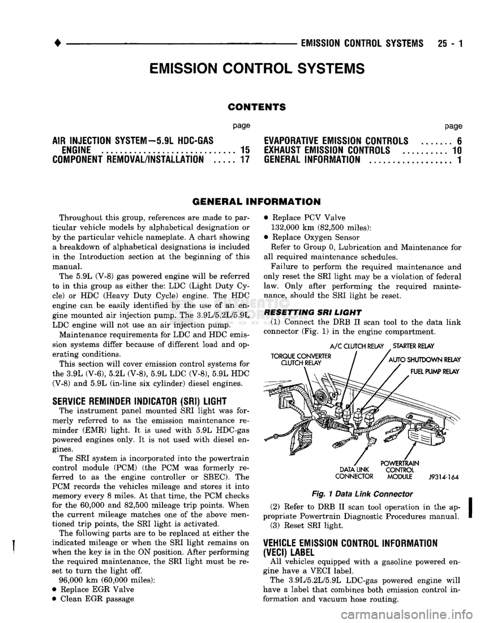
(1) Connect
the
DRB
II
scan tool
to
the
data link
connector (Fig.
1)
in
the engine compartment.
TORQUE CONVERTER
CLUTCH RELAY
A/C
CLUTCH RELAY
.
STARTER RELAY
AUTO
SHUTDOWN RELAY FUEL PUMP RELAY DATA LINK
CONNECTOR POWERTRAIN
CONTROL
MODULE
J9314-164
Fig.
1
Data
Link
Connector
(2) Refer
to
DRB
II
scan tool operation
in
the ap
propriate Powertrain Diagnostic Procedures manual. (3) Reset SRI light.
VEHICLE
EMISSION CONTROL INFORMATION
(VECI)
LABEL
All vehicles equipped with
a
gasoline powered
en
gine have
a
VECI label. The 3.9L/5.2L/5.9L LDC-gas powered engine will
have
a
label that combines both emission control
in
formation and vacuum hose routing.
EMISSION CONTROL
SYSTEMS
Page 1489 of 1502
25
- 12
EMISSION
CONTROL
SYSTEMS
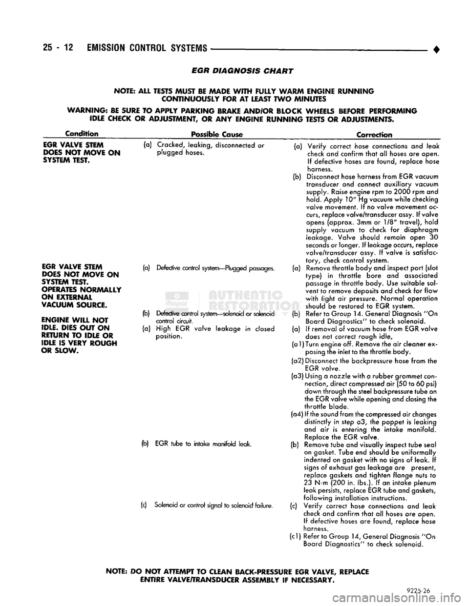
EGR
DIAGNOSIS
CHART
NOTE: ALL TESTS MUST BE MADE
WITH
FULLY
WARM ENGINE RUNNING CONTINUOUSLY FOR
AT
LEAST TWO MINUTES
WARNING: BE SURE
TO
APPLY PARKING BRAKE AND/OR BLOCK WHEELS BEFORE PERFORMING IDLE CHECK
OR
ADJUSTMENT,
OR ANY
ENGINE RUNNING TESTS
OR
ADJUSTMENTS.
Condition
Possible Cause
Correction
EGR
VALVE STEM
DOES
NOT MOVE
ON
SYSTEM
TEST.
(a) Cracked, leaking, disconnected or
plugged hoses.
EGR
VALVE STEM
DOES
NOT MOVE
ON
SYSTEM
TEST.
OPERATES
NORMALLY
ON EXTERNAL
VACUUM
SOURCE.
ENGINE
WILL
NOT
IDLE.
DIES OUT
ON
RETURN
TO
IDLE
OR
IDLE
IS
VERY ROUGH
OR SLOW.
(a) Defective control system—Plugged passages.
(b) Defective control system—solenoid or solenoid control circuit,
(a) High EGR valve leakage in closed
position.
(b) EGR tube to intake manifold leak.
(c) Solenoid or control signal to solenoid failure. (a)
(b)
(a)
(b)
(a) Verify correct hose connections and leak
check and confirm that alt hoses are open.
If defective hoses are found, replace hose
harness.
Disconnect hose harness from EGR vacuum
transducer and connect auxiliary vacuum supply. Raise engine rpm to 2000 rpm and hold. Apply 10" Hg vacuum while checking
valve movement. If no valve movement oc
curs,
replace valve/transducer assy. If valve
opens (approx. 3mm or 1/8" travel), hold
supply vacuum to check for diaphragm
leakage. Valve should remain open 30
seconds or longer. If leakage occurs, replace
valve/transducer assy. If valve is satisfac
tory, check control system. Remove throttle body and inspect port (slot
type) in throttle bore and associated passage in throttle body. Use suitable sol
vent to remove deposits and check for flow
with light air pressure. Normal operation
should be restored to EGR system. Refer to Group 14. General Diagnosis "On
Board Diagnostics" to check solenoid.
If removal of vacuum hose from EGR valve
does not correct rough idle,
(a
1)
Turn
engine off. Remove the air cleaner ex posing the inlet to the throttle body.
(a2) Disconnect the backpressure hose from the EGR valve.
(a3) Using a nozzle with a rubber grommet con nection, direct compressed air (50 to 60 psi)
down through the steel backpressure tube on
the EGR valve while opening and closing the
throttle blade.
(a4) If the sound from the compressed air changes distinctly in step a3, the poppet is leaking
and air is entering the intake manifold. Replace the EGR valve.
Remove tube and visually inspect tube seal
on gasket. Tube end should be uniformally
indented on gasket with no signs of leak. If
signs of exhaust gas leakage are present, replace gaskets and tighten flange nuts to
23 N-m (200 in. lbs.). If an intake plenum
leak persists, replace EGR tube and gaskets,
following installation instructions.
Verify correct hose connections and leak
check and confirm that all hoses are open. If defective hoses are found, replace nose
harness.
(cl) Refer to Group 14, General Diagnosis "On Board Diagnostics" to check solenoid. (b)
(c)
NOTE:
DO
NOT
ATTEMPT
TO CLEAN BACK-PRESSURE EGR VALVE, REPLACE
ENTIRE VALVE/TRANSDUCER ASSEMBLY
IF
NECESSARY.
9225-26