1993 DODGE TRUCK clutch
[x] Cancel search: clutchPage 1461 of 1502
24 - 24
HEATING
AND AIR
CONDITIONING
(3) Support the compressor on the 4 mounting ears
at the compressor rear. If a vise is being used, clamp
only on the mounting ears. Never clamp on the com
pressor body.
(4) Align rotor assembly squarely on the front
housing hub.
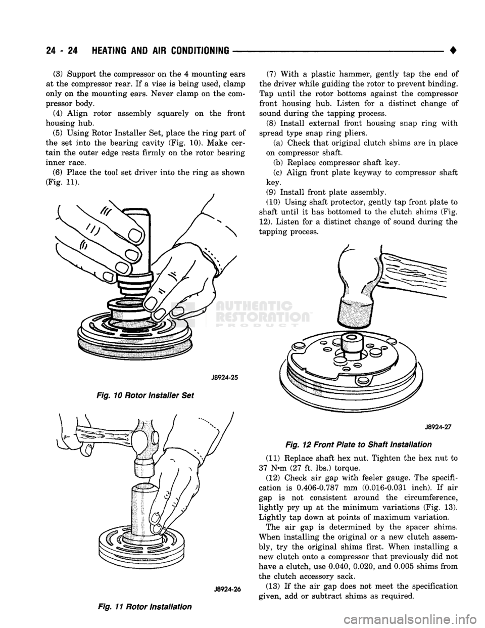
(5)
Using Rotor Installer Set, place the ring part of
the set into the bearing cavity (Fig. 10). Make cer
tain the outer edge rests firmly on the rotor bearing
inner race.
(6) Place the tool set driver into the ring as shown
(Fig. 11).
J8924-25
Fig. 10 Rotor installer Set
J8924-26
Fig. 11 Rotor Installation (7) With a plastic hammer, gently tap the end of
the driver while guiding the rotor to prevent binding.
Tap until the rotor bottoms against the compressor front housing hub. Listen for a distinct change of sound during the tapping process.
(8) Install external front housing snap ring with
spread type snap ring pliers.
(a) Check that original clutch shims are in place
on compressor shaft.
(b) Replace compressor shaft key.
(c) Align front plate keyway to compressor shaft
key.
(9) Install front plate assembly.
(10) Using shaft protector, gently tap front plate to
shaft until it has bottomed to the clutch shims (Fig.
12).
Listen for a distinct change of sound during the
tapping process.
J8924-27
Fig. 12 Front Plate to Shaft Installation
(11) Replace shaft hex nut. Tighten the hex nut to
37 N*m (27 ft, lbs.) torque.
(12) Check air gap with feeler gauge. The specifi
cation is 0.406-0.787 mm (0.016-0.031 inch). If air
gap is not consistent around the circumference,
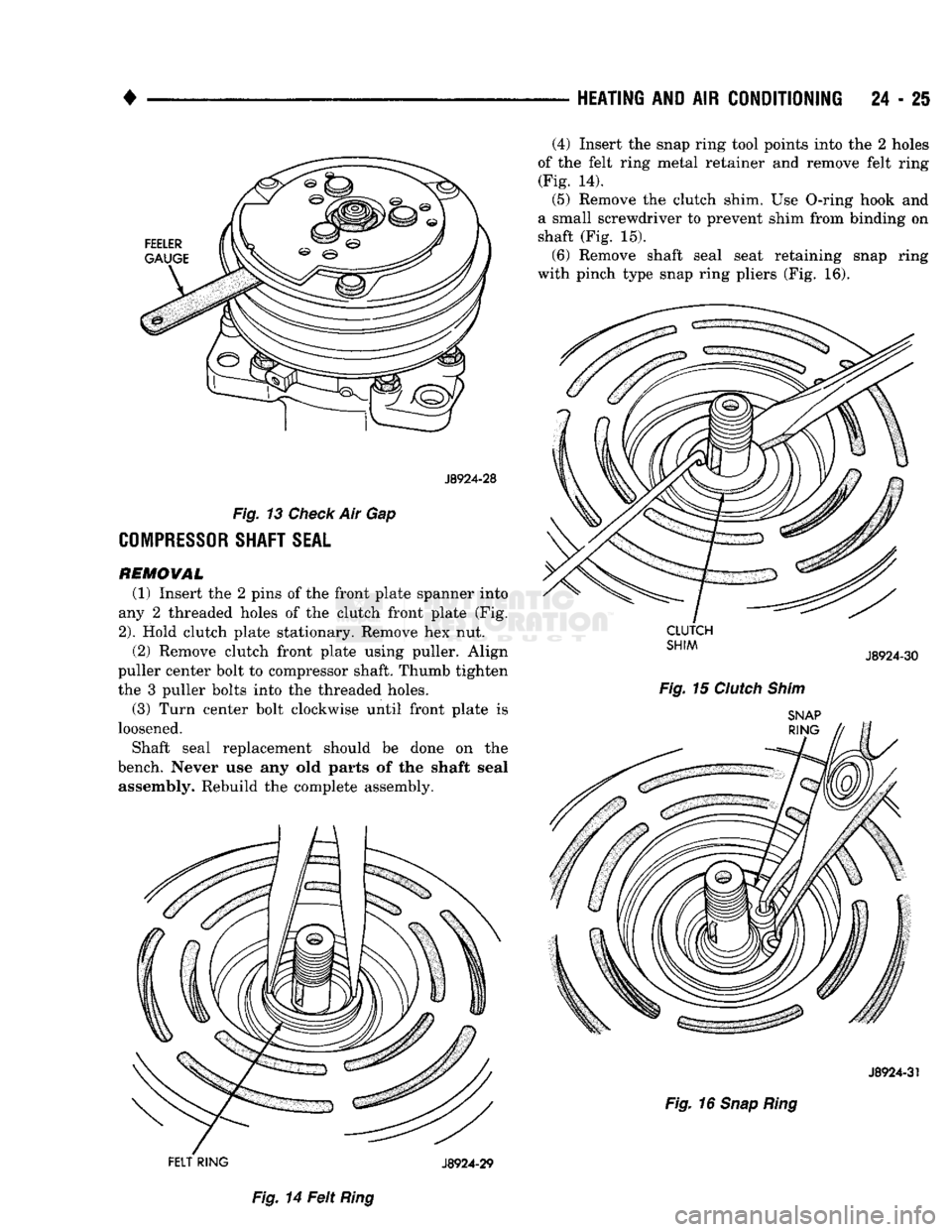
lightly pry up at the minimum variations (Fig. 13).
Lightly tap down at points of maximum variation.
The air gap is determined by the spacer shims.
When installing the original or a new clutch assem
bly, try the original shims first. When installing a new clutch onto a compressor that previously did not
have a clutch, use 0.040, 0.020, and 0.005 shims from
the clutch accessory sack.
(13) If the air gap does not meet the specification
given, add or subtract shims as required.
Page 1462 of 1502
•
HEATING
AND AIR
CONDITIONING
24 - 25
J8924-28
Fig.
13
Check
Air Gap
COMPRESSOR
SHAFT
SEAL
REMOWAL (1) Insert the 2 pins of the front plate spanner into
any 2 threaded holes of the clutch front plate (Fig.
2).
Hold clutch plate stationary. Remove hex nut. (2) Remove clutch front plate using puller. Align
puller center bolt to compressor shaft. Thumb tighten
the 3 puller bolts into the threaded holes.
(3) Turn center bolt clockwise until front plate is
loosened.
Shaft seal replacement should be done on the
bench. Never use any old parts of the shaft seal assembly. Rebuild the complete assembly. (4) Insert the snap ring tool points into the 2 holes
of the felt ring metal retainer and remove felt ring (Fig. 14). (5) Remove the clutch shim. Use O-ring hook and
a small screwdriver to prevent shim from binding on
shaft (Fig. 15).
(6) Remove shaft seal seat retaining snap ring
with pinch type snap ring pliers (Fig. 16). J8924-31
Fig.
16
Snap Ring
Fig.
14 Felt
Ring
Page 1464 of 1502
•
HEATING
AND AIR
CONDITIONING
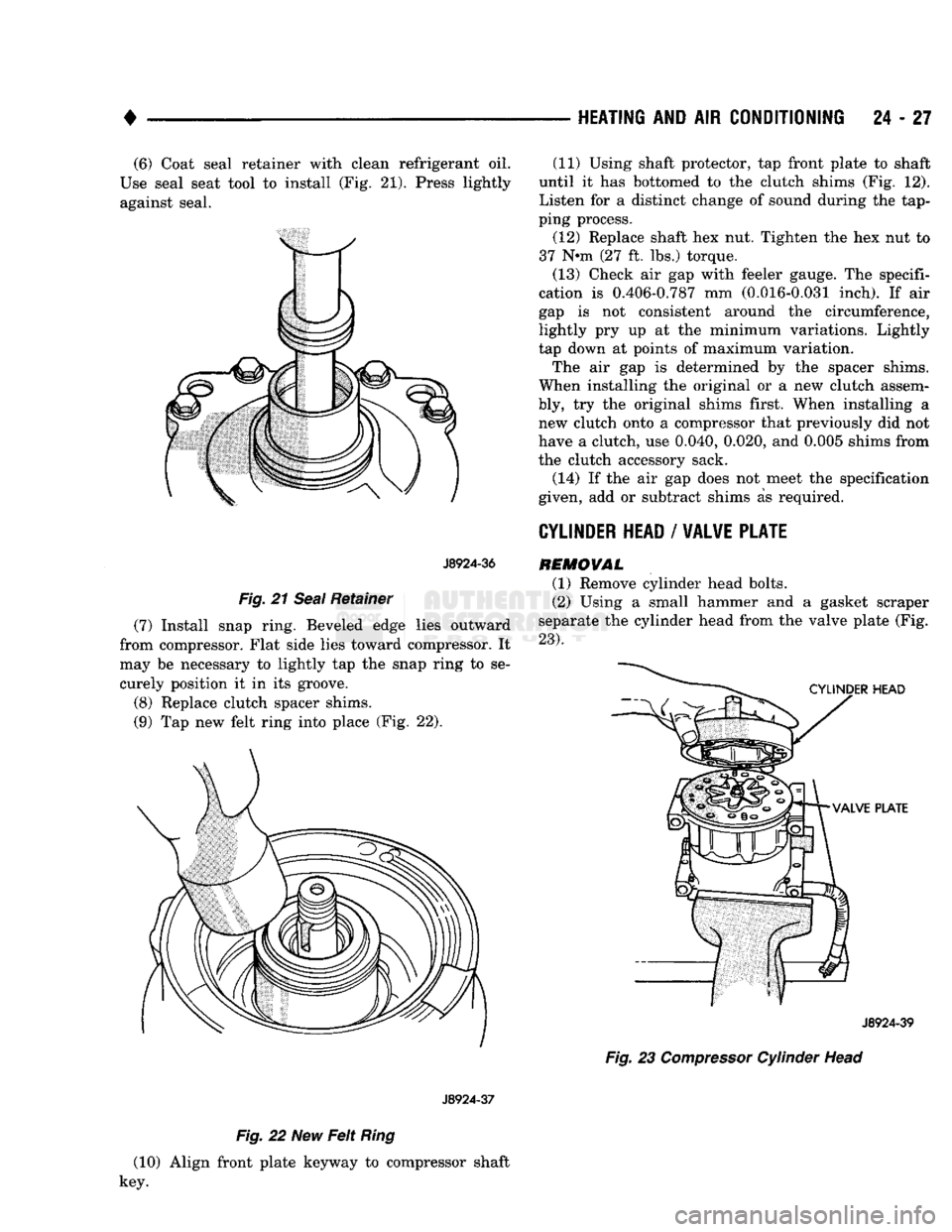
24 - 27 (6) Coat seal retainer with clean refrigerant oil.
Use seal seat tool to install (Fig. 21). Press lightly against seal.
J8924-36
Fig.
21
Seal
Retainer
(7) Install snap ring. Beveled edge lies outward
from compressor. Flat side lies toward compressor. It
may be necessary to lightly tap the snap ring to se curely position it in its groove.
(8) Replace clutch spacer shims.
(9) Tap new felt ring into place (Fig. 22).
J8924-37
Fig.
22 New
Felt
Ring
(10) Align front plate keyway to compressor shaft
key. (11) Using shaft protector, tap front plate to shaft
until it has bottomed to the clutch shims (Fig. 12).
Listen for a distinct change of sound during the tap
ping process.
(12) Replace shaft hex nut. Tighten the hex nut to
37 N-m (27 ft. lbs.) torque.
(13) Check air gap with feeler gauge. The specifi
cation is 0.406-0.787 mm (0.016-0.031 inch). If air
gap is not consistent around the circumference,
lightly pry up at the minimum variations. Lightly
tap down at points of maximum variation.
The air gap is determined by the spacer shims.
When installing the original or a new clutch assem
bly, try the original shims first. When installing a new clutch onto a compressor that previously did not
have a clutch, use 0.040, 0.020, and 0.005 shims from
the clutch accessory sack.
(14) If the air gap does not meet the specification
given, add or subtract shims as required.
CYLINDER
HEAD
/
VALVE PLATE
REMOVAL
(1) Remove cylinder head bolts.
(2) Using a small hammer and a gasket scraper
separate the cylinder head from the valve plate (Fig.
23).
J8924-39
Fig.
23
Compressor
Cylinder Head
Page 1466 of 1502
HEATING
AND
AIR
CONDITIONING
24 - 29
CLIMATE CONTROL
SYSTEM
INDEX
page
Air Conditioner Distribution
and
Spot Cooler
Ducts-Center
. . 38
Air Conditioner Distribution
and
Spot Cooler
Ducts-Left Bi-Level
38
Air Conditioner Distribution
and
Spot Cooler
Ducts-Right
Bi-Level
38
Air
Outlet
Assemblies Right
Side
.............
38
Control Test
......
30
Defroster Duct
34
Electrical Controls
and
Circuits
30
Electronic Temperature Cycling Switch
37
Evaporator Control Unit
. . 34
GENERAL
INFORMATION
This
air
conditioner
is
designed specifically
for
con
ventional
cab
trucks with
the
heater-evaporator
package designed
to fit
under
the
instrument panel.
The system
is
manually controlled
by the
operator. Controls have been kept simple
for
ease
of
service and operation. In
the
blend
air
reheat
air
conditioning unit,
all
the
air
entering
the
system passes through
the
evap orator.
A
selected portion passes through
the
heater
core depending
on the
position
of the
blend
air
door.
The system controls
are
located
in the
center
of the
instrument panel within easy reach
of the
driver.
The combination electrical
and
vacuum switch con
trols
the
compressor clutch, mode
of
operation
and
blower. Modes
are Off, Max. A/C, A/C,
Vent, Heat and Defrost.
A
4-speed blower motor switch controls
the amount
of air
flow.
The
evaporator-heater pack age includes:
•
The
blower motor. • Intake duct with outside
air
recirculating door.
• Evaporator coil
• Heater core.
• Defroster discharge doors.
• Blower motor speed resistors.
• Vacuum harness.
• Vacuum actuators.
•
A/C air
outlets
to the
distribution ducts. Defrost, Heat,
A/C and
Vent modes automatically
supply
100%
outside
air.
The
air
distribution ducts supply
air
from
the
unit
to
4
panel mounted, fully directional, outlets.
The
faceplate
has 2
outlets
and 2 are
snapped into
the
panel
on the
right side. Satisfactory performance
of the air
conditioning
and heating system
is
dependent upon correct opera
tion
and
adjustment
of all
operating controls.
The in
spections, tests
and
adjustments should
be
used
to
locate
the
cause
of a
malfunction.
The
tests
in
this
page
Evaporator Heater Assembly
36
Expansion
(H)
Valve
37
Faceplate
32
General Information
. 29
Heater Assembly
. 33
Heater Control
32
Louver
Assemblies
39
Operation
of All
Controls
29
Resistor
Block
33
Temperature
and
Mode Control Cables
. 32
Vacuum
Actuators
36
Vacuum
Controls
and
Circuits
30
manual have been arranged
in a
logical sequence
that
has
proved
to be the
surest
and
shortest route
to
accurate diagnosis.
It is
recommended that they
be
followed
and
performed
in the
order they
are
pre sented.
OPERATION
OF ALL
CONTROLS
Operation must
be
tested
as
described
in the
fol
lowing sequence: (1) Inspect, test,
and
adjust compressor drive belt.
(2) Start engine
and
adjust engine speed
to 1,300
RPM.
Use a
reliable tachometer. (3) Move temperature control lever
to
Cool position
and mode lever
to A/C
position. (4)
The
inlet
air
door should
be
open
to
outside
air.
Open vehicle windows. (5) Test
the
blower operation
at all 4
speed posi
tions.
If the
blower does
not
operate correctly refer
to
Electrical Controls
and
Circuit. Leave
the
blower switch
in the
HIGH position.
(6)
The
compressor should
be
running
and the air
conditioning system
in
operation. In addition
to the six
position push button selector,
the
A/C
Heater control consists
of:
TEMPERATURE LEVER-Controls
the
tempera-.
ture
of the
discharge
air in all
modes except
MAX
A/C
and Off
when
the
vacuum operated water valve is closed. Moving
the
lever
to the
left provides cooler
air
and
moving
it to the
right provides warmer
air.
BLOWER SWITCH-The system blower
can be op
erated
at 4
speeds.
•
LOW at the
bottom. • MEDIUM
1 at the
lower center.
• MEDIUM
2 at the
upper center.
• HIGH
at the top
switch position. The blower will
be on and
operating
at the
speed
selected,
in all
push button positions except
Off.
AIR DIRECTIONAL VANES-Air
is
delivered
through
4
panel outlets.
The 4
outlets
are
adjustable
Page 1467 of 1502
24 - 30
HEATING
AND AIR
CONDITIONING
•
up,
down or to either side and can be shut off by
pushing the vanes up. Floor air is delivered through
the lower outlets.
VACUUM CONTROLS
AND
CIRCUITS
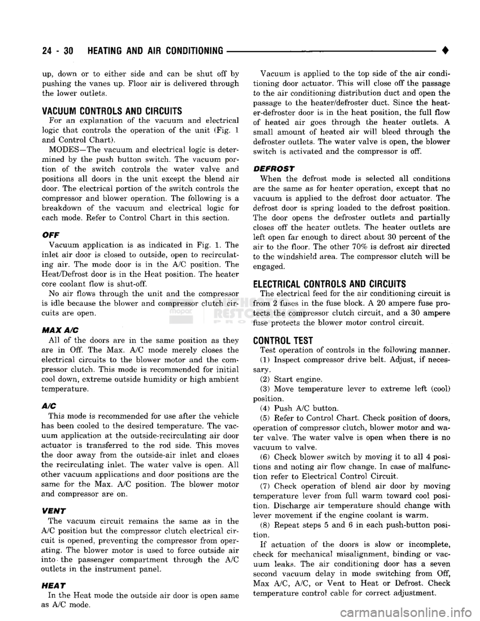
For an explanation of the vacuum and electrical
logic that controls the operation of the unit (Fig. 1
and Control Chart). MODES—The vacuum and electrical logic is deter
mined by the push button switch. The vacuum por
tion of the switch controls the water valve and
positions all doors in the unit except the blend air
door. The electrical portion of the switch controls the compressor and blower operation. The following is a
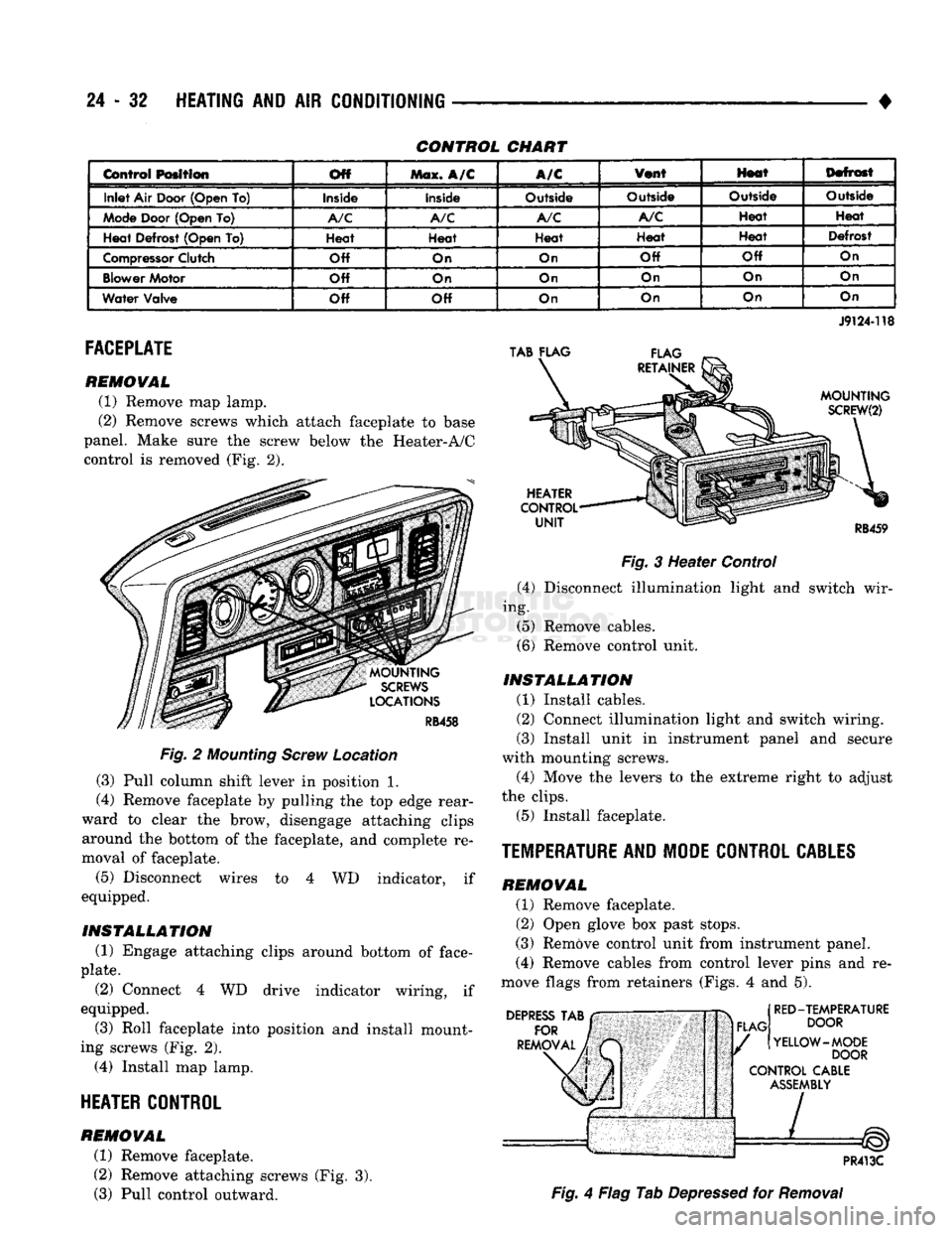
breakdown of the vacuum and electrical logic for each mode. Refer to Control Chart in this section.
OFF Vacuum application is as indicated in Fig. 1. The
inlet air door is closed to outside, open to recirculat
ing air. The mode door is in the A/C position. The
Heat/Defrost door is in the Heat position. The heater core coolant flow is
shut-off.
No air flows through the unit and the compressor
is idle because the blower and compressor clutch cir
cuits are open.
MAX A/C All of the doors are in the same position as they
are in Off. The Max. A/C mode merely closes the
electrical circuits to the blower motor and the com
pressor clutch. This mode is recommended for initial cool down, extreme outside humidity or high ambient
temperature.
A/C
This mode is recommended for use after the vehicle
has been cooled to the desired temperature. The vac
uum application at the outside-recirculating air door actuator is transferred to the rod side. This moves
the door away from the outside-air inlet and closes
the recirculating inlet. The water valve is open. All
other vacuum applications and door positions are the
same for the Max. A/C position. The blower motor and compressor are on.
VENT The vacuum circuit remains the same as in the
A/C position but the compressor clutch electrical cir
cuit is opened, preventing the compressor from oper ating. The blower motor is used to force outside air
into the passenger compartment through the A/C
outlets in the instrument panel.
HEAT
In the Heat mode the outside air door is open same
as A/C mode. Vacuum is applied to the top side of the air condi
tioning door actuator. This will close off the passage
to the air conditioning distribution duct and open the
passage to the heater/defroster duct. Since the heat er-defroster door is in the heat position, the full flow
of heated air goes through the heater outlets. A
small amount of heated air will bleed through the
defroster outlets. The water valve is open, the blower
switch is activated and the compressor is off.
DEFROST When the defrost mode is selected all conditions
are the same as for heater operation, except that no
vacuum is applied to the defrost door actuator. The defrost door is spring loaded to the defrost position.
The door opens the defroster outlets and partially closes off the heater outlets. The heater outlets are
left open far enough to direct about 30 percent of the
air to the floor. The other 70% is defrost air directed
to the windshield area. The compressor clutch will be engaged.
ELECTRICAL CONTROLS AND CIRCUITS
The electrical feed for the air conditioning circuit is
from 2 fuses in the fuse block. A 20 ampere fuse pro
tects the compressor clutch circuit, and a 30 ampere fuse protects the blower motor control circuit.
CONTROL TEST
Test operation of controls in the following manner.
(1) Inspect compressor drive belt. Adjust, if neces
sary. (2) Start engine. (3) Move temperature lever to extreme left (cool)
position. (4) Push A/C button.
(5)
Refer to Control Chart. Check position of doors,
operation of compressor clutch, blower motor and wa
ter valve. The water valve is open when there is no
vacuum to valve. (6) Check blower switch by moving it to all 4 posi
tions and noting air flow change. In case of malfunc
tion refer to Electrical Control Circuit. (7) Check operation of blend air door by moving
temperature lever from full warm toward cool posi
tion. Discharge air temperature should change with lever movement if the engine coolant is warm. (8) Repeat steps 5 and 6 in each push-button posi
tion. If actuation of the doors is slow or incomplete,
check for mechanical misalignment, binding or vac uum leaks. The air conditioning door has a seven
second vacuum delay in mode switching from Off,
Max A/C, A/C, or Vent to Heat or Defrost. Check
temperature control cable for correct adjustment.
Page 1469 of 1502
24 - 32
HEATING
AND AIR
CONDITIONING
CONTROL CHART
Control
Position Off
Max.
A/C
A/C
Vont
Hoot
Defrost
Inlet Air Door (Open To)
Inside Inside
Outside Outside
Outside
Outside
Mode
Door (Open To)
A/C A/C A/C A/C
Heat
Heat
Heat Defrost (Open To) Heat
Heat Heat Heat Heat
Defrost
Compressor
Clutch Off
On On
Off Off
On
Blower
Motor Off
On On On
On On
Water Valve Off Off
On On On
On
FACEPLATE
REMOVAL
(1) Remove map lamp.
(2) Remove screws which attach faceplate to base
panel. Make sure the screw below the Heater-A/C
control is removed (Fig. 2).
MOUNTING
SCREWS
LOCATIONS
RB458
Fig.
2
Mounting
Screw
Location
(3) Pull column shift lever in position 1.
(4) Remove faceplate by pulling the top edge rear
ward to clear the brow, disengage attaching clips around the bottom of the faceplate, and complete re
moval of faceplate.
(5)
Disconnect wires to 4 WD indicator, if
equipped.
INSTALLATION
(1) Engage attaching clips around bottom of face
plate.
(2) Connect 4 WD drive indicator wiring, if
equipped.
(3) Roll faceplate into position and install mount
ing screws (Fig. 2). (4) Install map lamp.
HEATER
CONTROL
REMOVAL
(1) Remove faceplate.
(2) Remove attaching screws (Fig. 3). (3) Pull control outward.
TAB FLAG
FLAG
RETAINER
J9124-118
MOUNTING
SCREW(2)
HEATER
CONTROL
UNIT
RB459
Fig.
3 Heater Control (4) Disconnect illumination light and switch wir
ing.
(5) Remove cables.
(6) Remove control unit.
INSTALLATION
(1) Install cables.
(2) Connect illumination light and switch wiring.
(3) Install unit in instrument panel and secure
with mounting screws.
(4) Move the levers to the extreme right to adjust
the clips.
(5) Install faceplate.
TEMPERATURE
AND MODE CONTROL
CABLES
REMOVAL
(1) Remove faceplate.
(2) Open glove box past stops.
(3) Remove control unit from instrument panel.
(4) Remove cables from control lever pins and re
move flags from retainers (Figs. 4 and 5).
DEPRESS
TAB
FOR
REMOVAL FLAG
RED-TEMPERATURE
DOOR
YELLOW-MODE DOOR
CONTROL
CABLE
ASSEMBLY
PR413C
Fig.
4 Flag Tab
Depressed
for
Removal
Page 1476 of 1502
•
HEATING AND AIR CONDITIONING 24 - 39 LOU¥ER ASSEMBLIES
REMOVAL
(1) Remove faceplate.
(2) Set faceplate with trim surface down, insert a
small screwdriver tip into the outlet housing pivot
hole.
(3)
While forcing down louver assembly pivot pin,
pull louver assembly out of rear of faceplate (Fig. 9).
INSTALLATION
(1) Position louver assembly, bottom pivot first,
into the faceplate outlet housing. The bottom pivot
pin is a smaller diameter than the top pivot pin.
(2) While deflecting the upper louver assembly
pivot pin, carefully swing the assembly into housing, so the felt pads are not damaged. Ensure top and bot
tom pivot pins are properly engaged. (3) Install faceplate.
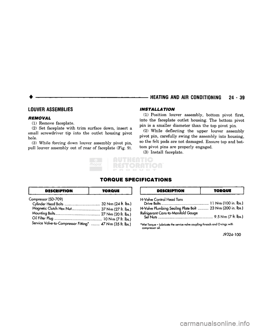
TORQUE
SPECIFICATIONS
DESCRIPTION
fORQUE
DESCRIPTION
Compressor (SD-709) Cylinder Head Bolts 32 N-m (24 ft. lbs.)
Magnetic Clutch Hex Nut... 37 N-m (27 ft. lbs.)
Mounting Bolts 27 N-m (20 ft. lbs.)
Oil Filter Plug
10
N-m (7 ft. lbs.)
Service Valve-to-Compressor Fitting* ........ 47 N-m (35 ft. lbs.)
TORQUE
H-Valve Control Head Torx Drive Bolts
11
N-m
(100
in. lbs.)
H-Valve Plumbing Sealing Plate Bolt 23 N-m (200 in. lbs.)
Refrigerant Cans-to-Manifold Gauge Set Nuts 9.5 N-m (7
ft.
lbs.)
•Wet Torque - Lubricate the service valve
coupling
threads and
O-rings
with
compressor
oil.
J9324-100
Page 1478 of 1502
•
EMISSION
CONTROL
SYSTEMS
25
- 1
CONTENTS
page page
AIR INJECTION
SYSTEM-o
9L
HDC-GAS EVAPORATIVE EMISSION CONTROLS
6
ENGINE
15
EXHAUST EMISSION CONTROLS
10
COMPONENT
REMOVAL/INSTALLATION
17
GENERAL INFORMATION
1
GENERAL
INFORMATION
Throughout this group, references are made
to
par
ticular vehicle models
by
alphabetical designation
or
by the particular vehicle nameplate.
A
chart showing a breakdown
of
alphabetical designations
is
included
in
the
Introduction section
at
the
beginning
of
this
manual.
The 5.9L (V-8) gas powered engine will
be
referred
to
in
this group
as
either the: LDC (Light Duty Cy cle)
or
HDC (Heavy Duty Cycle) engine.
The
HDC
engine can
be
easily identified
by
the
use
of
an en
gine mounted
air
injection pump. The 3.9L/5.2L/5.9L
LDC engine will not use
an
air
injection pump.
Maintenance requirements for LDC and HDC emis
sion systems differ because
of
different load
and
op
erating conditions. This section will cover emission control systems
for
the 3.9L (V-6), 5.2L (V-8), 5.9L LDC (V-8), 5.9L HDC (V-8) and 5.9L (in-line six cylinder) diesel engines.
SERVICE
REMINDER INDICATOR
(SRI)
LIGHT
The instrument panel mounted SRI light was for
merly referred
to as the
emission maintenance
re
minder (EMR) light.
It is
used with 5.9L HDC-gas
powered engines only.
It is
not
used with diesel
en
gines.
The SRI system
is
incorporated into the powertrain
control module (PCM)
(the
PCM
was
formerly
re
ferred
to as the
engine controller
or
SBEC).
The
PCM records
the
vehicles mileage and stores
it
into
memory every
8
miles. At that time, the PCM checks
for the 60,000 and 82,500 mileage trip points. When
the current mileage matches one
of
the above men
tioned trip points,
the
SRI light
is
activated.
The following parts are
to
be replaced
at
either the
indicated mileage
or
when the SRI light remains
on
when the key
is in
the ON position. After performing
the required maintenance,
the
SRI light must
be
re set
to
turn the light
off.
96,000
km
(60,000 miles):
• Replace EGR Valve
• Clean EGR passage • Replace PCV Valve
132,000
km
(82,500 miles):
• Replace Oxygen Sensor
Refer
to
Group
0,
Lubrication and Maintenance
for
all required maintenance schedules.
Failure
to
perform
the
required maintenance
and
only reset the SRI light may be
a
violation of federal
law. Only after performing
the
required mainte
nance, should the SRI light
be
reset.
RESETTING
SRI
LIGHT
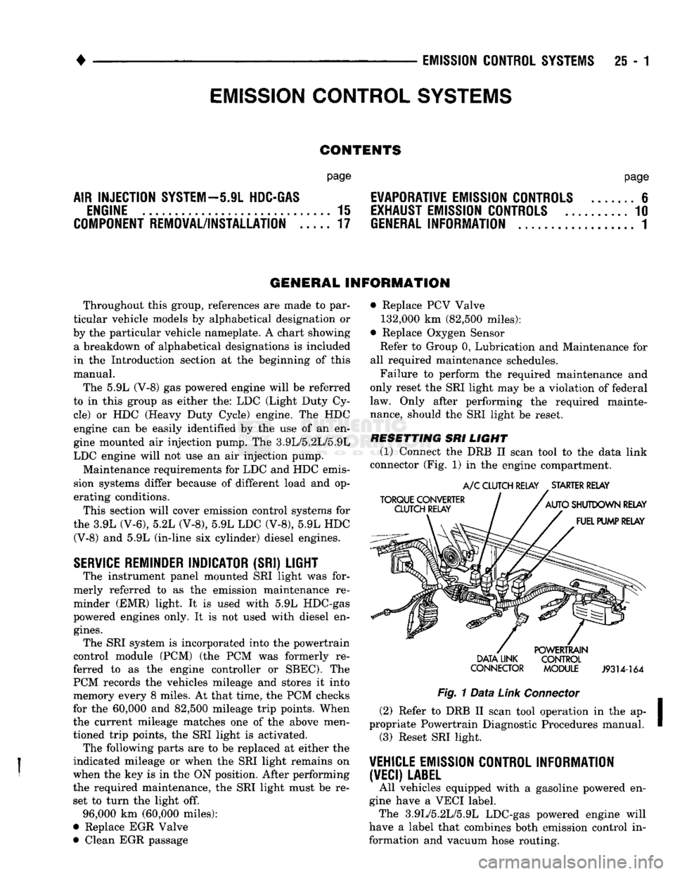
(1) Connect
the
DRB
II
scan tool
to
the
data link
connector (Fig.
1)
in
the engine compartment.
TORQUE CONVERTER
CLUTCH RELAY
A/C
CLUTCH RELAY
.
STARTER RELAY
AUTO
SHUTDOWN RELAY FUEL PUMP RELAY DATA LINK
CONNECTOR POWERTRAIN
CONTROL
MODULE
J9314-164
Fig.
1
Data
Link
Connector
(2) Refer
to
DRB
II
scan tool operation
in
the ap
propriate Powertrain Diagnostic Procedures manual. (3) Reset SRI light.
VEHICLE
EMISSION CONTROL INFORMATION
(VECI)
LABEL
All vehicles equipped with
a
gasoline powered
en
gine have
a
VECI label. The 3.9L/5.2L/5.9L LDC-gas powered engine will
have
a
label that combines both emission control
in
formation and vacuum hose routing.
EMISSION CONTROL
SYSTEMS